Advertisement
Quick Links
Comp No 7647618 - 01 (10/15)
United Kingdom
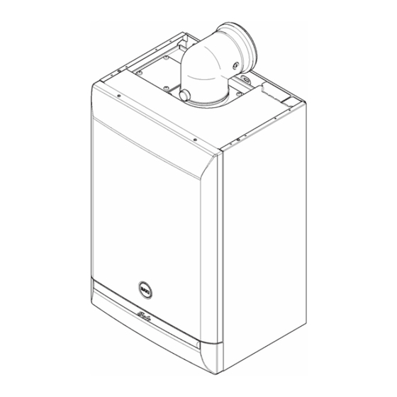
Solo Heat IE 12 - 15 - 18 - 24
Gas Fired Wall Mounted Condensing Boiler
Installation and Service Manual
These instructions include the Benchmark Commissioning Checklist and should be left with the user for safe keeping. They must be read in conjunction with the Flue Installation
Guide.
page 1
Natural Gas
Baxi Solo 12 Heat IE ErP
Baxi Solo 15 Heat IE ErP
Baxi Solo 18 Heat IE ErP
Baxi Solo 24 Heat IE ErP
© Baxi Heating UK Ltd 2015 All rights reserved. No part of this publication may be reproduced or transmitted in any form or by any means, or stored in any retrieval system of any
nature (including in any database), in each case whether electronic, mechanical, recording or otherwise, without the prior written permission of the copyright owner, except for
permitted fair dealing under Copyrights, Designs and Patents Act 1988.
Applications for the copyright owner's permission to reproduce or make other use of any part of this publication should be made, giving details of the proposed use, to the following
address:
The Company Secretary, Baxi Heating UK Ltd,
Brooks House, Coventry Road, Warwick. CV34 4LL
Full acknowledgement of author and source must be given.
WARNING: Any person who does any unauthorised act in relation to a copyright work may be liable to criminal prosecution and civil claims for damages.
© Baxi Heating UK Ltd 2015
Advertisement

Related Manuals for Baxi Solo Heat IE 12


Summary of Contents for Baxi Solo Heat IE 12
- Page 1 Baxi Solo 24 Heat IE ErP © Baxi Heating UK Ltd 2015 All rights reserved. No part of this publication may be reproduced or transmitted in any form or by any means, or stored in any retrieval system of any nature (including in any database), in each case whether electronic, mechanical, recording or otherwise, without the prior written permission of the copyright owner, except for permitted fair dealing under Copyrights, Designs and Patents Act 1988.
- Page 2 page 2 Legislation This company declare that no substances harmful to health are contained in the appliance or used during appliance manufacture. The appliance is suitable only for installation in IE and should be installed in accordance with the rules in force, and only used in a suitably ventilated location. The installation must be carried out by a competent Person and installed in accordance with the current edition of I.S.
- Page 3 1. The Baxi Solo Heat IE range are gas fired room sealed fan assisted condensing central heating boilers. 2. The maximum output of the Baxi Solo 12 Heat IE is 11.82 kW, 15 model is 15.24 kW, 18 model is 17.81 kW, 24 model is 22.0 kW. All boilers automatically adjust their outputs according to the system load.
- Page 4 Fig. 2 page 6 2.0 General Layout 2.1 Layout (Figs. 3,4,5 & 6) 1. Wall Plate 2. Flue Elbow 3. Heat Exchanger 4. Burner 5. Air Box 6. Fan Protection Thermostat 7. Fan Assembly 8. Condensate Trap 9. PCB Housing Assembly 10.
- Page 5 Fig. 3, Fig. 4, Fig. 5 & Fig. 6 page 7 3.0 Appliance Operation 1. Switched Live On: When the switched live switches on if the flow temperature is less than the set point then pump overrun occurs. When the switched live switches on if the flow temperature is greater than the set point then pump overrun occurs.
- Page 6 9. Ignition Lockout: The pump, fan, spark generator and gas valve are off. The boiler can only be reset by manually using the reset button. page 8 4.0 Technical Data 4.2 Baxi Solo 12,15, 18, 24 Heat IE ErP Appliance Type...
- Page 7 CAT I Appliance Category Heat Input Qn Hs (Gross) 12 model 13.34 10.2 15 model 16.88 10.2 18 model 20.18 10.2 24 model 24.50 10.2 Heat Output Pn (Non Condensing 70°C Mean Water Temp) 12 model 11.82 9.14 15 model 15.24 9.14 18 model...
- Page 8 The test data from which it has been calculated has been certified by 0086. page 9 4.2 Technical Parameters Technical parameters for boiler space heaters Baxi Solo Heat IE ErP Condensing boiler Low-temperature boiler B1 boiler Cogeneration space heater...
- Page 9 page 10 5.0 Dimensions and Fixings Fig. 7 Fig. 8 page 11 6.0 System Details 6.1 Water Circulating Systems 1. The appliance is suitable for use with open vent fully pumped systems and sealed systems . The following conditions should be observed on all systems: The static head must not exceed 30m (100ft) of water.
- Page 10 All recirculatory water systems will be subject to corrosion unless an appropriate water treatment is applied. This means that the efficiency of the system will deteriorate as corrosion sludge accumulates within the system, risking damage to pump and valves, boiler noise and circulation problems. When fitting new systems flux will be evident within the system, which can lead to damage of system components.
- Page 11 Fig. 11 If Conditions Require, This System Possible Fig. 12 6.5 Pump 1. Providing that the cold feed and open vent pipe are positioned correctly (e.g. the system is not prone to pumping over, air entrainment etc.) the pump may be fitted on the primary return pipe.
- Page 12 Y Plan, Room Thermostat System, CH Interlocked By Room Thermostat At least the Radiator(s) near the Room Thermostat not TRV'd Pump run from Switched Live By-pass permitted but not required for Part L1 compliance S Plan, Room Thermostat System, CH Interlocked By Room Thermostat At least the Radiator(s) near the Room Thermostat not TRV'd Pump run from Switched Live By-pass permitted but not required for Part L1 compliance...
- Page 13 7. HOT WATER STORAGE - The hot water storage vessel must be of the indirect coil type. All components used in the system must be suitable for operation at 110°C and at the pressure allowed by the safety valve. Fig. 13 Method of determining minimum valve of expansion vessel volume for sealed systems using Baxi Boilers Multiply Total Vessel Charge...
- Page 14 Vessel Charge Pressure = 1.0 bar Initial System Pressure = 1.5 bar Then :- 75 x 0.152 = 11.4 litres Expansion Vessel Volume NOTE Where a vessel of the calculated size is not obtainable then the next available larger size should be used. Fig.
- Page 15 7.2 Ventilation of Compartments 1. Where the boiler is installed in a cupboard or compartment, no air vents are required for cooling purposes providing that the minimum dimensions below are maintained. Sides 15mm 200mm Bottom 50mm Front 30mm 2. If the boiler is installed in a smaller cupboard or compartment it must be ventilated according to BS 5440 Part 2 and the minimum clearances given in section 4.0 "Technical Data"...
- Page 16 Fig. 16 7.5 Electrical Supply 1. External wiring must be correctly earthed, polarised and in accordance with relevant regulations/rules. In IE reference should be made to the current edition of ETCI rules. 2. The mains supply is 230V ~ 50Hz fused at 3A. NOTE: "The method of connection to the electricity supply must facilitate complete electrical isolation of the appliance".
- Page 17 pumped into an external soil & vent pipe vii) to a drain or gully with extended external run & trace heating It is strongly recommended to discharge internally into the household drainage system. If connecting to a rain water drain, that drain MUST discharge into a foul drain. i) Termination to an internal soil and vent pipe ii) External termination via internal discharge branch e.g.
- Page 18 iv) Termination to a purpose made soakaway page 19 12. A boiler discharge pump is available, 'MULTIFIT' part no. 720648301. This pump will dispose of both condensate & high temperature water from the relief valve. It has a maximum head of 5 metres. Follow the instructions supplied with the pump. 13.
- Page 19 vi) pumped into an external soil & vent pipe vii) to a drain or gully with extended external run & trace heating page 20 7.7 Flue NOTE: Due to the high efficiency of the boiler a plume of water vapour will be discharged from the flue.
- Page 20 This should be taken into account when siting the flue terminal. 1. The following guidelines indicate the general requirements for siting balanced flue terminals. For IE recommendations are given in the current edition of I.S. 813 "Domestic Gas Installations". 2. If the terminal discharges onto a pathway or passageway, check that combustion products will not cause a nuisance and that the terminal will not obstruct the passageway. 3.
- Page 21 IMPORTANT: If fitting a Plume Displacement Flue Kit, the air inlet must be a minimum of 150mm from any opening windows or doors (see Section 9.0). Fig. 17c page 21 8.0 Flue Options 8.1 Horizontal Flue Systems Concentric The maximum equivalent lengths are 4m (horizontal) or (vertical). Their lengths exclude the standard elbow and flue/terminal assembly (horizontal) and terminal assembly (vertical).
- Page 22 page 22 8.2 Twin & Vertical Flue Systems Concentric The maximum equivalent lengths are 4m (vertical). Their lengths exclude the standard elbow and terminal assembly (vertical). Twin Flue The total maximum equivalent flue length is 150m. NOTE: Each 1m of flue duct should be calculated as 2m. Any additional "in line"...
- Page 23 The total equivalent length for this example is 17.2 + 34.4 = 51.6 metres. AIR DUCT Equivalent Length Value No of fittings/pipes Sub total 1m extension 5.0m 135°bend 1.3m 2.6m 91.5°bend 4.8m 9.6m Equivalent Length Air Duct = 17.2m FLUE DUCT Equivalent Length Value No of fittings/pipes Sub total 1m extension 10.0m...
- Page 24 Equivalent Length Flue Duct = 34.4m page 23 8.3 Flue Accessories Key Accessory Size Code No FLUE GROUP B Concentric Flue System 110mm diameter Horizontal Flue Terminal 850mm 243013BAX Horizontal Flue Terminal (incl. elbow) 236921 Flue Extension 1000mm 241695 500mm 241694 250mm 241692...
- Page 25 page 24 8.4 For Vertical Flue Systems 1. Undo the screws securing the blanking plate to the boiler top panel. Discard the plate. 2. Fix the vertical adaptor and gasket to the top panel with the previously removed screws. 8.5 For Twin Flue Systems 1.
- Page 26 For Twin Flues page 25 8.6 For Roof Terminals 1. In the case of a pitched roof 25 - 50 degrees, position the lead tile to replace/flash over existing roof tiling. Make an aperture in the roof suitable for the lower tube of the roof terminal and ensure the integrity of the roof cover is maintained.
- Page 27 8.7 Flue Dimensions The standard horizontal flue kit allows for flue lengths between 270mm (10 " ) and 800mm (32") from elbow to terminal (Fig. 18). The maximum permissible equivalent flue length is: 4 metres. NOTE: Each additional 45° of flue bend will account for an equivalent flue length of 0.5m. e.g..
- Page 28 Content of kit 1 70/110 Concentric Flue 1 1m 70 Dia Exhaust Flue Pipe 2 Support Brackets 1 93° Elbow/Plume Outlet Assembly 1 Flue Trim 2 "O" Rings 1 Elbow with Gasket 1. This kit is recommended for installations where the condensate plume emitted from the flue may cause a nuisance or affect the surroundings. 2.
- Page 29 As can be seen this corresponds with 14 metres. Therefore, the total equivalent length of the 70Ø exhaust can be up to 14 metres. Any elbow equivalencies must be accounted for i.e. 93° elbows are equal to 1 metre, each 45° elbow to 0.5 metres. Flue Length - Worked Example Baxi Solo Heat IE Fig. D below an additional 93° elbow and pair of 45°...
- Page 30 Example 2 Flue Lengths - OK Example 3 Flue Lengths - OK Fig. D page 28 9.3 General Fitting Notes - P.D.K. 1. Cut a hole in the external wall which the horizontal concentric flue assembly will pass through. 2. When completed the terminal must be at least 2 metres above ground level (Fig.
- Page 31 6. Connect any extensions that are being used to the concentric assembly. Engage the extension or concentric assembly in the boiler flue elbow. 7. Fit the boiler flue elbow to the boiler top panel, ensuring the gasket is in place (Fig.
- Page 32 Fig. G page 29 16. For aesthetic purposes it is permissible to route the 70Ø exhaust in an enclosed box, but the air inlet and plume outlet MUST remain in free air. 17. It is also possible to separate the plume outlet from the 93° elbow to allow the flue to be installed as shown in Fig.
- Page 33 page 30 10.0 Installation Check Site Requirements (section 7) before commencing. 10.1 Initial Preparation The gas supply, gas type and pressure must be checked for suitability before connection (see Section 7.4). 1. Cut the banding and remove the fixing template, wall plate and literature pack (Fig.
- Page 34 Fig. 22 page 31 10.2 Preparing The Boiler (Figs. 22a & 23) 1. Remove the outer carton and packaging. 2. Lift the outercase upwards and remove. 3. Remove the internal packaging. Fig. 22a Fig. 23 page 32 10.3 Fitting The Boiler (Fig.
- Page 35 1. Remove the screw and retaining bracket from the wall plate spring clip. 2. Offer up the boiler to the wall plate using the lifting points shown in Fig. 24 and locate the rear bottom edge onto the self locating support at the base of the wall plate. (See Safe Manual Handling) NOTE: When installing in a Loft/Small Compartment, access for lifting the boiler from the front can be gained for two people using the lifting points.
- Page 36 Fig. 24, Fig. 25 & Fig. 25a page 33 10.6 Making the Gas Connection 1. Connect the gas supply to the G1/2 ( " BSPT Internal) gas tap. This is located on the lower right side of the boiler, access by hinging down the PCB housing (see Fig.
- Page 37 1. The standard flue is suitable for lengths 270mm minimum to 800mm maximum (measured from the edge of the flue elbow outlet). Rear Flue: maximum wall thickness - 630mm Side Flue: maximum wall thickness - 565mm (left or right) 2. For rear exit - measure the wall thickness (Fig.
- Page 38 30). Apply a suitable mastic to the inside of the trim and press against the wall finish, making sure the brickwork is dust free and dry. 13. If necessary fit a terminal guard (see Section 8.8). VERTICAL FLUEING 1. Only a flue approved with the Baxi Solo Heat IE range can be used. Fig. 28...
- Page 39 Fig. 29 & Fig. 29a Fig. 30 page 35 10.8 Making The Electrical Connections WARNING: This appliance must be earthed 1. The electrical connections are on the right hand side of the unit. 2. Route the incoming electrical cable/s through the grommet in the support bracket. This will prevent damage to the cable. 3.
- Page 40 Fig. 31 & Fig. 33 page 36 11.0 Electrical 11.1 Schematic Wiring Diagram...
- Page 41 Key To Wiring Colours b - Blue - Red bk - Black g - Green w - White g/y- Green/Yellow br - Brown op - Opaque gy - Grey - Yellow page 37 11.2 Illustrated Wiring Diagram...
- Page 42 Wiring Key - Blue bk - Black br - Brown - Red - White g/y - Green/Yellow - Green gy - Grey op - Opaque - Yellow page 38 12.0 Commissioning the Boiler 12.1 Commissioning the Boiler WARNING: The PCB Control and Fan Assembly are 325 Vdc. Isolate at supply before access.
- Page 43 That the boiler has been installed in accordance with these instructions. The integrity of the flue system and the flue seals. The integrity of the boiler combustion circuit and the relevant seals. Proceed to put the boiler into operation as follows: Fig.
- Page 44 3. Ensure that this inlet pressure can be obtained with all other gas appliances in the property working. Measure the Gas Rate 4. With any other appliances & pilot lights turned OFF the gas rate can be measured. It should be as shown in Section 4.0 Technical Data.
- Page 45 Fig. 37 Fig. 38 page 41 14.0 Servicing the Boiler 14.1 Annual Servicing 1. For reasons of safety and economy, it is recommended that the boiler is serviced annually. Servicing must be performed by a competent person in accordance with B.S. 7967- 2.
- Page 46 The person carrying out a combustion measurement should have been assessed as competent in the use of a flue gas analyser and the interpretation of the results. The flue gas analyser used should be one meeting the requirements of BS7927 or BS-EN50379-3 and be calibrated in accordance with the analyser manufacturers' requirements.
- Page 47 Fig. 40 & Fig. 41 page 43 11. To clean the heat exchanger and burner proceed as follows: a) Disconnect the electrical leads to the fan component protection sensor (Fig. 42). b) Loosen the screw retaining the gas injector pipe at the venturi (Fig.
- Page 48 Fig. 41a , Fig. 42 & Fig. 43 Fig. 44 page 44 15.0 Changing Components 15.1 Changing Components...
- Page 49 IMPORTANT: When changing components ensure that both the gas and electrical supplies to the boiler are isolated before any work is started. "The boiler cannot be switched off at the boiler, therefore it is important to isolate the electrical supply at the mains fuse." Hazardous materials are not used in the construction of these products, however reasonable care during service is recommended.
- Page 50 Fig. 45 & Fig. 46 page 45 15.3 Flowswitch (Fig. 1. Drain the boiler (see Section 15.1 paragraph 2 & 3). 2. Remove the two screws on the support bracket. 3. Remove the clip securing the flow pipe to the flowswitch. 4.
- Page 51 Fig. 47 15.4 PCB (Figs. 48 & 49) WARNING: The PCB Control and Fan Assembly are 325 Vdc. Isolate at supply before access. 1. Pull the control knob off the spindle and remove the plastic button cover. Refit them onto the new PCB (Fig.
- Page 52 Fig. 49a Fig. 49b page 46 The fan and venturi, gas valve, injector pipe, condensate trap, fan protection sensor, spark and sensing electrodes can be accessed and changed on the removal of the airbox door panel. 1. Remove the airbox door panel by loosening the four 1/4 turn screws (Fig.
- Page 53 Fig. 50, Fig. 51 & Fig. 52 page 47 The removal of the fan is necessary to enable the changing of the injector pipe, condensate trap and gas valve (see section 15.7). 15.8 Injector Pipe (Fig. 1. Remove the injector pipe by pulling out from the 'O' ring joint in the gas valve. 2.
- Page 54 1. Remove the Control PCB (see Section 15.4). 2. Isolate gas supply and disconnect the gas tap by removing the four screws. 3. Undo the case pressure pipe from the gas valve. 4. Disconnect the electrical plug from the gas valve. 5.
- Page 55 2. Disconnect the condensate drain (outside the boiler) from the condensate trap. 3. Undo the condensate trap lock nut and remove the trap from the boiler. Disconnect the sensor leads. 4. Fit the new condensate trap and reassemble in reverse order. 5.
- Page 56 Fig. 55, Fig. 56, Fig. 57 & Fig. 58 Fig. 59 page 49 15.13 Heat Exchanger Lower Insulation Pad (Fig. 1. Remove all components in the base of the airbox.
- Page 57 2. Remove the burner (see section 15.11). 3. Remove the four bolts securing the combustion box base. 4. Remove the combustion box base. 5. Pull the central insulation panel down from the centre of the heat exchanger and remove the lower insulation pad. 6.
- Page 58 page 51 17.0 Fault Finding NOTE: The fan is supplied with 325 Vdc. Fan Fault Finding should only be carried out after the boiler has been electrically isolated. General Fault Finding should only be carried out by someone who is appropriately qualified.
- Page 59 page 52 ELECTRICAL SUPPLY...
- Page 60 page 53 DRY-FIRE...
- Page 61 page 54 IGNITION LOCKOUT...
- Page 62 page 55 OVERHEAT LOCKOUT...
- Page 63 page 56 FAN LOCKOUT...
- Page 64 THERMISTOR page 57 GAS BOILER COMMISSIONING CHECKLIST...
- Page 65 page 58 SERVICE INTERVAL RECORD It is recommended that your heating system is serviced regularly and that you complete the appropriate Service Interval Record Below. Service Provider. Before completing the appropriate Service Interval Record below, please ensure you have carried out the service as described in the boiler manufacturer's instructions.
- Page 66 All goods are sold subject to our standard Conditions of Sale which are available on request. BAXI A Trading Division of Baxi Heating UK Ltd (3879156) Brooks House, Coventry Road, Warwick. CV34 4LL...
- Page 67 © Baxi Heating UK Ltd 2015 Comp No 7647618 - 01 (10/15) page 60...
Need help?
Do you have a question about the Solo Heat IE 12 and is the answer not in the manual?
Questions and answers