
Related Manuals for SPEEDY-LIFT SP-TOY21


Summary of Contents for SPEEDY-LIFT SP-TOY21
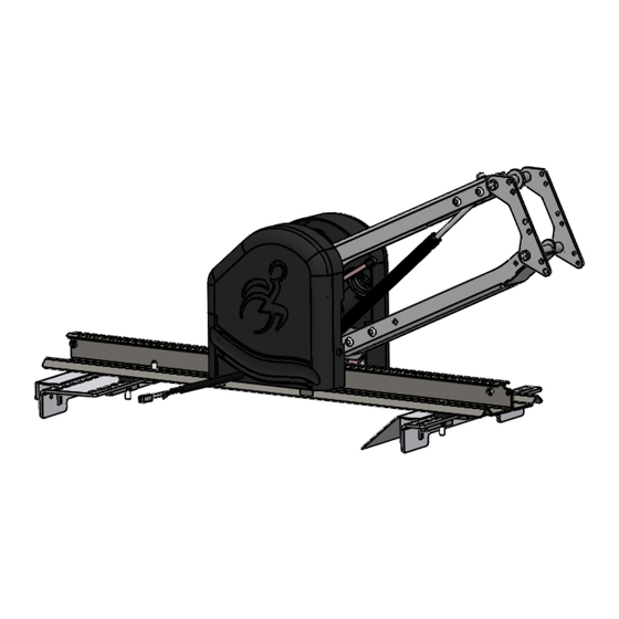
- Page 1 SPEEDY-LIFT INSTALLATION MANUAL SP-TOY21 TOYOTA SIENNA 2021 & UP DRIVER & PASSENGER SIDES Instalation is the same for driver and passenger side aplications...
-
Page 2: Table Of Contents
ITEM PART NUMBER DESCRIPTION SPEEDY-LIFT TOYOTA SIENNA 2021 & UP SP000-01 Mechanism Assembvly SP600B Housing Cover Assembly -Black- SP700B Hook Assembly -Black- SP740 Wheelchair support SL800 Electrical Kit -Alone- SP-TOY21-00 Installation Kit PRD 110-104 Round washer head tapping screw #8 x 1/2... -
Page 3: Sp600B
ITEM PART NUMBER DESCRIPTION SPEEDY-LIFT TOYOTA SIENNA 2021 & UP SP-TOY21-01 Outside Floor Adapter SP-TOY21-02 Inside Floor Adapter SL-UNI-07 Nut for SPEEDY-LIFT rail SL-UNI-08 Rail Spacer SP-TOY21-03 3/16" Spacer SP000-01 Mechanism Assembvly SL-UNI-09 Rail Spacer Washer PRD BSHCS51618114P Button Head Socket Cap Screw Zinc Plated 5/16-18 x 1 1/4... - Page 4 ITEM PART NUMBER DESCRIPTION SPEEDY-LIFT TOYOTA SIENNA 2021 & UP SP-TOY21-01 Outside Floor Adapter SP-TOY21-02 Inside Floor Adapter SL-UNI-07 Nut for SPEEDY-LIFT rail SL-UNI-08 Rail Spacer SP-TOY21-03 3/16" Spacer SP000-01 Mechanism Assembvly SL-UNI-09 Rail Spacer Washer PRD BSHCS51618114P Button Head Socket Cap Screw Zinc Plated 5/16-18 x 1 1/4...
-
Page 5: Sp700B
ITEM PART NUMBER DESCRIPTION SPEEDY-LIFT TOYOTA SIENNA 2021 & UP SP700B Hook Assembly -Black- PRD 337-211P Button Head Socket Cap Screw Zinc Plated 5/16-18 x 1/2 PART NUMBER SP-TOY21 DESCRIPTION SPEEDY-LIFT Toyota Sienna 2021 & Up 4 of 5 |tech@adaptsolutions.ca|866.641.0419|418.889.9838 fax... -
Page 6: Prd 2946
ITEM PART NUMBER DESCRIPTION SPEEDY-LIFT TOYOTA SIENNA 2021 & UP SP740 Wheelchair support PRD 337-211P Button Head Socket Cap Screw Zinc Plated 5/16-18 x 1/2 PRD 2946 Flange Locknut Zinc Plated 5/16-18 PART NUMBER SP-TOY21 DESCRIPTION SPEEDY-LIFT Toyota Sienna 2021 & Up 5 of 5 |tech@adaptsolutions.ca|866.641.0419|418.889.9838 fax... - Page 7 1. Remove the driver or passenger side second row seat. Slide the seat platform completely forwards and then move back to the first ajustement. Remove the covers unplug the electrical connecters and the four bolts holding the seat, two on the front and two on the back. Remove the seat. Keep the OEM bolts to install the floor adpters.
- Page 8 2. Install the two floor adapters using the OEM bolts. Use the adapter # SP-TOY21-01 on the outboard seat mounting point, and use the # SP-TOY21-02 adapter on the inboard seat mounting point. NOTE: For the seven-passenger model, the interior bracket must face towards the interior of the vehicle.
- Page 9 3. With the seat removed, the seat ocupation sensor curcuit will have to have a resistance installed to prevent a error code. Insert the resistance ito the plug and cover with the shrink wrap and attache under the adapter bracket with the provided zip ties. NOTE:The 2022 model also has a seat belt pretentioner this will also have to have the provided shunt installed into the plug to avoid a airbag light.
- Page 10 4. The SPEEDY-LIFT up down and in out motors can be disengaged manualy to slide the SPEEDY-LIFT in and out and move the arm up and down. NOTE; when disengaing the arm it will spring up as the arm of the SPEEDY-LIFT is aided by a 100 lbs gas shock hold the arm firmly when disengaging.
- Page 11 Use the two extra shims on the left hand side to level the SPEEDY-LIFT 6. Place the washer over the SPEEDY-LIFT track and use the 5/16” X 1 1/4” button head bolts to lign up the washer plate, the SPEEDY-LIFT track and the black plastic shim.
- Page 12 8. Power the SPEEDY-LIFT all the way out. Attach the wheelchair hook and support assembly SP700 to the head of the SPEEDY-LIFT. The hight of the hook assembly may be ajusted depending on the hight or tyle of wheel chair. Remove the plastic housing covers.
- Page 13 10. Press the ‘OUT’ button on the hand held pendant until the upper wheelchair support bracket is positioned 1/4” to 1/2” below the rigidizer bar on the wheelchair. Adjust the stop down bolt so that the arm stops in this position.
- Page 14 11. To properly position the lower support arms, back the wheelchair up over the upper wheelchair support bracket. Press and hold the ‘IN’ button until the wheelchair barely starts lo to lift off the ground. Then ajust the lower support arms to the wheelchair. Adjust the liftting angle of the wheelchair by sliding the lower supports forward or back.
- Page 15 NOTE: The SPEEDY-LIFT must be in the full up position. Proper adjustment will ensure that the locking mecanism and cable will not fail. If the cable is adjusted with the SPEEDY-LIFT not in the full up possition, the cable will fail and the locking mecanism will no longer work.
-
Page 16: Warning Decals
WARNING DECALS After completing the installation of the SPEEDY LIFT, please take the time to install the warning decals. NOTE: The surface must be clean, dry and an ambient temperature for the sticker to stick to the surface. • Start by locating a position to install the decals. •... -
Page 17: Troubleshooting
TROUBLESHOOTING PROBLEM POSSIBLE CAUSES Bad electrical connections. Check and clean corrosion from all connections including the car’s battery cable connections. Hand pendant wire problem. Check hand pendant wire to make sure it is properly plugged. Check the wire for any cuts. If so, replace the wire. - Page 18 ELECTRICAL INSTALLATION FOR SPEEDY-LIFT 1. Thread the lead power cable (red +) under the doorstep moulding and thru the firewall. WARNING: Pass thru a grommet in the firewall to prevent the cable from chaffing. 2. Install the circuit breaker near the battery and then connect the battery to the circuit breaker.
- Page 19 ELECTRICAL BOX CONNECTIONS ASENTO SPEEDY LIFT with...
- Page 20 SPEEDY LIFT ALONE SPEEDY LIFT CORD RED = 12 V POWER SUPPLY BLACK = GROUNDED TO THE CHASSIS...
-
Page 21: Year Limited Warranty
Adapt-Solutions # 1 Ltd. (Adapt Solutions), warrants to the original purchaser of an XL-BASE, XL-SEAT, HI-LIFT, SPEEDY-LIFT, XL-BOARD, POWER-PULL or ASENTO that the equipment is free from defects in material and workmanship for a period of three years from date of purchase.
Need help?
Do you have a question about the SP-TOY21 and is the answer not in the manual?
Questions and answers