
Related Manuals for SPEEDY-LIFT SP-CHR17R


Summary of Contents for SPEEDY-LIFT SP-CHR17R
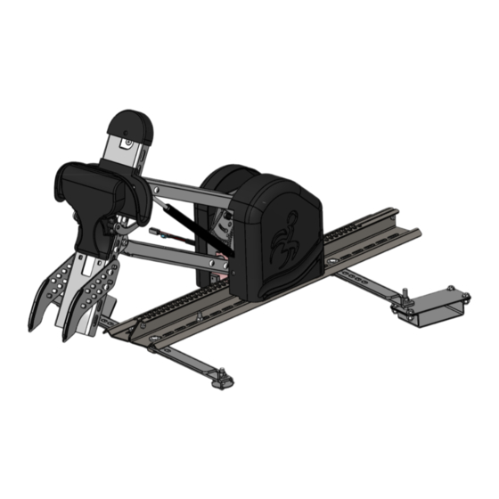
- Page 1 SPEEDY-LIFT INSTALLATION MANUAL SP-CHR17R CHRYSLER PACIFICA PASSENGER SIDE 2017 & UP...
- Page 2 ITEM PART NUMBER DESCRIPTION KIT SPEEDY-LIFT 2 CHRYSLER PACIFICA 2017+ SP000 Mechanism Assembvly SP100-01 Rail Assembly SP600B Housing Cover Assembly -Black- SP700B Hook Assembly -Black- SP740 Wheelchair support SL800 Electrical Kit -Alone- SL-CHR17R-00 Floor Installation Kit -Right- SL-CHR17R-01 Outside Floor Adapter -Right-...
- Page 3 ITEM PART NUMBER DESCRIPTION KIT SPEEDY-LIFT 2 CHRYSLER PACIFICA 2017+ SL-CHR17R-01 Outside Floor Adapter -Right- SL-CHR17-02 Inside Floor Adapter SL-CHR17R-03 Rear Fixing -Right- SL-CHR17-04 Front Fixing SL-CHR17-05 Front Fixing SL-CHR17-06 Front Fixing SL-CHR17-07 Rear Fixing SCALE 1:7 PRD 110-104 Round washer head tapping screw #8 x 1/2...
- Page 4 ITEM PART NUMBER DESCRIPTION KIT SPEEDY-LIFT 2 CHRYSLER PACIFICA 2017+ SP000 Mechanism Assembvly SP100-01 Rail Assembly SP600B Housing Cover Assembly -Black- SL-UNI-07 Nut for SPEEDY-LIFT rail SL-UNI-08 Rail Spacer SL-UNI-09 Rail Spacer Washer PRD 110-104 Round washer head tapping screw #8 x 1/2...
- Page 5 ITEM PART NUMBER DESCRIPTION KIT SPEEDY-LIFT 2 CHRYSLER PACIFICA 2017+ SP700B Hook Assembly -Black- PRD 337-211P Button Head Socket Cap Screw Zinc Plated 5/16-18 x 1/2 SCALE 1:6 SCALE 1:5 PART NUMBER SP-CHR17R DESCRIPTION 4 of 5 Speedy-Lift 2 Kit -Right- |tech@adaptsolutions.ca|866.641.0419|418.889.9838 fax...
- Page 6 ITEM PART NUMBER DESCRIPTION KIT SPEEDY-LIFT 2 CHRYSLER PACIFICA 2017+ SP740 Wheelchair support PRD 337-211P Button Head Socket Cap Screw Zinc Plated 5/16-18 x 1/2 PRD 2946 Flange Locknut Zinc Plated 5/16-18 SCALE 1:4 SCALE 1:6 PART NUMBER SP-CHR17R DESCRIPTION...
- Page 7 NOTE: If installing a LINK with a SPEEDY-LIFT, install the LINK floor adapter brakets at the same time. 1. Stow the second row seats. Install the provided brackets # SL-CHR17-04 and # SL-CHR17-05 using the four provided 5/16-18x3/4 bolts, nuts and washers. Align the protruding bolt with the hole in the stow and go cover, then tighten down all the bolts.
- Page 8 3. Remove the rear cover of the stow and go mechanism to gain access to the seat attachement bolts. Remove the left hand bolt of the two central bolts and install the bracket aligning with the # SL-CHR17R-03 slot then tighten down 4.
- Page 9 5. Two coresponding holes will now have to be drilled 3/8 diameter in the rear cover to allow the bolts to pass through. For the center hole, use the provided stencil. For the exterior hole, cut off the plastic clip and drill the hole directly through the center of the clip.
- Page 10 # SL-CHR17R-01 and the interior floor bracket # SL-CHR17- 02 using the provided 3/8 nuts and flat washers. 7. Place the SPEEDY-LIFT in the vehicle on the floor adaptors using the plastic shims between the SPEEDY-LIFT and the floor adapters. Center the SPEEDY-LIFT in the door opening.Place the...
- Page 11 To reengage lift up the lever. You may have to move the arm and the unit back and forth. 9. Place the washer over the SPEEDY-LIFT track and use the 5/16” X 1 1/4” button head bolts to lien up the washer plate, the SPEEDY-LIFT track and the black plastic shim. Secure the SPEEDY-...
- Page 12 ELECTRICAL INSTALLATION FOR SPEEDY-LIFT. 11. Power the SPEEDY-LIFT all the way out. Attach the wheelchair hook and support assembly SP700 to the head of the SPEEDY-LIFT. The height of the hook assembly may be adjusted depending on the height or style of the wheelchair.
- Page 13 13. Press the ‘OUT’ button on the hand held pendant until the upper wheelchair support bracket is positioned 1/4” to 1/2” below the rigidizer bar on the wheelchair. Adjust the stop down bolt so that the arm stops in this position. 14.
- Page 14 NOTE: The SPEEDY-LIFT must be in the full up position. Proper adjustment will ensure that the locking mecanism and cable will not fail. If the cable is adjusted with the SPEEDY-LIFT not in the full up possition, the cable will fail and the locking mecanism will no longer work.
-
Page 15: Warning Decals
WARNING DECALS After completing the installation of the SPEEDY LIFT, please take time to install the warning decals. NOTE: The surface must be clean, dry and at ambient temperature for the sticker to stick to the surface. Start by locating a position to install the decals. ... -
Page 16: Troubleshooting
TROUBLESHOOTING PROBLEM POSSIBLE CAUSES Bad electrical connections. Check and clean corrosion from all connections including the car’s battery cable connections. Hand pendant wire problem. Check hand pendant wire to make sure it is properly plugged. Check the wire for any cuts. If so, replace the wire. - Page 17 ELECTRICAL INSTALLATION FOR SPEEDY-LIFT 1. Thread the lead power cable (red +) under the doorstep molding and through the firewall. WARNING: Pass through a grommet in the firewall to prevent the cable from chaffing. 2. Install the circuit breaker near the battery and then connect the battery to the circuit breaker.
- Page 18 ELECTRICAL BOX CONNECTIONS ASENTO SPEEDY LIFT with...
- Page 19 SPEEDY LIFT ALONE SPEEDY LIFT CORD RED = 12 V POWER SUPPLY BLACK = GROUNDED TO THE CHASSIS...
-
Page 20: Year Limited Warranty
Adapt-Solutions # 1 Ltd. (Adapt Solutions), warrants to the original purchaser of an XL-BASE, XL-SEAT, HI-LIFT, SPEEDY-LIFT, XL-BOARD, POWER-PULL or ASENTO that the equipment is free from defects in material and workmanship for a period of three years from date of purchase.
Need help?
Do you have a question about the SP-CHR17R and is the answer not in the manual?
Questions and answers