Advertisement
Quick Links
INSTALLATION
INSTRUCTION
TABLE OF CONTENTS
GENERAL INFORMATION . . . . . . . . . . . . . . . . . 2
SAFETY . . . . . . . . . . . . . . . . . . . . . . . . . . . . . . . . . . 2
INSPECTION . . . . . . . . . . . . . . . . . . . . . . . . . . . . . . 2
LIMITATIONS. . . . . . . . . . . . . . . . . . . . . . . . . . . . . . 2
UNIT INSTALLATION . . . . . . . . . . . . . . . . . . . . . 2
LOCATION . . . . . . . . . . . . . . . . . . . . . . . . . . . . . . . . 2
GROUND INSTALLATION . . . . . . . . . . . . . . . . . . . . 3
ROOF INSTALLATION . . . . . . . . . . . . . . . . . . . . . . . 3
UNIT PLACEMENT . . . . . . . . . . . . . . . . . . . . . . . 3
VERIFY INDOOR REFRIGERANT ORIFICE . . . . . . 3
INSTALLATIONS REQUIRING TXV . . . . . . . . . . . . . 4
PIPING CONNECTIONS . . . . . . . . . . . . . . . . . . . 4
PRECAUTIONS DURING LINE INSTALLATION . . . 5
PRECAUTIONS DURING BRAZING OF LINES . . . . 5
PRECAUTIONS DURING BRAZING
ANGLE VALVE . . . . . . . . . . . . . . . . . . . . . . . . . . . . . 5
GENERAL INFORMATION & GROUNDING . . . . 7
FIELD CONNECTIONS CONTROL WIRING . . . 7
SYSTEM CHARGE . . . . . . . . . . . . . . . . . . . . . . . . . . 7
SYSTEM START-UP . . . . . . . . . . . . . . . . . . . . . . 8
ENERGIZE CRANKCASE HEATER . . . . . . . . . . . . . 8
INSTRUCTING THE OWNER . . . . . . . . . . . . . . . . . 10
INDICATIONS OF PROPER OPERATION . . . . . . . 10
MAINTENANCE . . . . . . . . . . . . . . . . . . . . . . . . . . . 10
CAUTION:READ ALL SAFETY GUIDES BEFORE YOU
START TO INSTALL YOUR UNIT.
SAVE THIS MANUAL
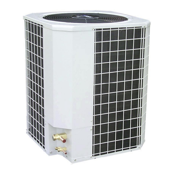
LUXAIRE
PERFORMANCE PLUS
SPLIT-SYSTEM
AIR CONDITIONER
12 SEER 1-1/2 TO 5 TONS
MODELS:
HADC-F018
HADC-F024
HADC-F030
HADC-F036
HADC-F042
HADC-F048
HADC-F060
035-16440-001 Rev. A (501)
Advertisement

Subscribe to Our Youtube Channel
Related Manuals for York International LUXAIRE PERFORMANCE PLUS HADC-F018


Summary of Contents for York International LUXAIRE PERFORMANCE PLUS HADC-F018
- Page 1 INSTALLATION LUXAIRE INSTRUCTION PERFORMANCE PLUS SPLIT-SYSTEM AIR CONDITIONER 12 SEER 1-1/2 TO 5 TONS TABLE OF CONTENTS GENERAL INFORMATION ....2 SAFETY ........2 INSPECTION .
- Page 2 035-16440-001 Rev. A (501) GENERAL INFORMATION This instruction covers the installation of the following Luxaire Performance Plus air conditioning units. These outdoor units are designed to be connected to a Incorrect installation may create a condition matching UPG indoor coil with sweat connection lines. These where the operation of the product could cause units are factory charged with refrigerant for a matching sys- personal injury or property damage.
- Page 3 035-16440-001 Rev. A (501) UNIT INSTALLATION Compressor tie-down bolts should remain tightened. Position the unit on the base provided. LOCATION Sit unit on the (4) rubber elevating grommets if provided. Before starting the installation, select and check the suitability Use grommet kit 1SG0601 if not provided. These should of the location for both the indoor and outdoor unit.
- Page 4 035-16440-001 Rev. A (501) rounded end toward the coil and the flat end outward per Install TXV equalizer line in 1/8 hole previously made in Figure 3. vapor line. Equalizer line can be bottomed out in vapor line as end of equalizer line is cut on 45 degrees angle to Thread the liquid line fitting back in place on the coil.
- Page 5 035-16440-001 Rev. A (501) NOTE: Pack fiber glass insulation and a sealing material such Using a larger than specified line size could result in as permagum, around refrigerant lines where they pene- oil return problems. Using too small a line will result trate a wall to reduce vibration and to retain some flexibil- in loss of capacity and other problems caused by ity.
- Page 6 035-16440-001 Rev. A (501) Connect the refrigerant lines using the following procedure. connection. After this connection has cooled, remove the nitrogen source from the liquid fitting service port. Remove the cap and Schrader core from both the liquid and vapor angle valve service ports at the outdoor unit. Replace the schrader cores in the liquid and vapor Connect low pressure nitrogen to the liquid line service valves.
- Page 7 035-16440-001 Rev. A (501) GENERAL INFORMATION & GROUNDING FIELD CONNECTIONS CONTROL WIRING Check the electrical supply to be sure that it meets the values Route low voltage wiring into bottom of control box as specified on the unit nameplate and wiring label. shown in Figure 7.
- Page 8 035-16440-001 Rev. A (501) Permanently stamp the unit data plate with the total Measure and record indoor wet bulb (WB) temperature amount of refrigerant in the system. using a sling psychrometer and the outdoor dry bulb (DB) temperature using a thermometer. Use one of the following charging methods whenever addi- tional refrigerant is required for the system charge.
- Page 9 035-16440-001 Rev. A (501) Table 1: SUPERHEAT VALUE OUTDOOR DB°F INDOOR WB °F Evaporator Entering Air °F Table 2: TEMPERATURE AND PRESSURE SUCTION SERVICE VALVE SUPERHEAT °F SUCTION PRESSURE PSIG ERVICE 61.5 64.2 67.1 70.0 73.0 76.0 79.2 82.4 Saturation Temperature Table 3: R-22 SATURATION PROPERTIES PRESSURE...
- Page 10 035-16440-001 Rev. A (501) INSTRUCTING THE OWNER If unit is not operating properly, check the following items before calling a serviceman: Assist owner with processing warranty cards. Review Owners Indoor section for dirty filter. Guide and provide a copy for the owner guidance on proper operation and maintenance.
- Page 11 035-16440-001 Rev. A (501) SERVICE RECORDS Unitary Products Group...
- Page 12 Subject to change without notice. Printed in U.S.A. 035-16440-001 Rev. A (501) Copyright © by York International Corp. 2001. All rights reserved. Supersedes: Nothing Unitary 5005 Norman Products York Group Drive 73069...
Need help?
Do you have a question about the LUXAIRE PERFORMANCE PLUS HADC-F018 and is the answer not in the manual?
Questions and answers