Table of Contents
Advertisement
Quick Links
Radiographic X-ray system
HF-525Plus
[Installation, Operation and Service Manual]
EcoRay Co., Ltd.
[57248] 60-10, Nanosandan 5-ro, Nam-myeon, Jangseong-gun, Jeollanam-do, Korea
Phone : +82 61 392 3251 / Fax : +82 613925266. www.eco-ray.co.kr
Tel)+82 70 7510 3405 Fax)+82 70 8630 3420
Obelis s.a
Bd. Général Wahis 53 1030 Brussels, BELGIUM
Seongdong-gu, Seoul, KOREA, 04778
Phone :+32 2 732 59 54
Phone: +82 613923251 / Fax: +82 613925266. www.eco-ray.co.kr
EcoRay Co., Ltd.
[57248] 전라남도 장성군 남면 나노산단5로 60-10
전화: 061-392-3251 / 팩스: 061-392-5266. www.eco-ray.co.kr
Fax: +32 2 732 60 03
Technical Publication
Document NO: SYSTEM-007-ENG (Rev.1.1)
Advertisement
Table of Contents
Troubleshooting

Related Manuals for Ecoray HF-525Plus


Summary of Contents for Ecoray HF-525Plus
-
Page 1: Technical Publication
Radiographic X-ray system HF-525Plus [Installation, Operation and Service Manual] EcoRay Co., Ltd. [57248] 60-10, Nanosandan 5-ro, Nam-myeon, Jangseong-gun, Jeollanam-do, Korea Phone : +82 61 392 3251 / Fax : +82 613925266. www.eco-ray.co.kr Tel)+82 70 7510 3405 Fax)+82 70 8630 3420 Obelis s.a... -
Page 2: Table Of Contents
2.7 Essential Performance ______________________________________________________________ 8 2.8 Intended Patient Population __________________________________________________________ 8 2.9 Operator Profile ____________________________________________________________________ 8 2.10 Symbols marked on HF-525Plus ______________________________________________________ 8 3. Safety_______________________________________________________________________________ 9 3.1 General safety _____________________________________________________________________ 9 3.2 Safety from Explosion or Electric Shock ________________________________________________ 10 3.3 Risk of collision ___________________________________________________________________ 10... - Page 3 HF-525Plus Installation, Operation and Service Manual 5. Installation of HF-525Plus ______________________________________________________________ 24 5.1 Conditions for installation ___________________________________________________________ 24 5.2 Equipment Dimensions _____________________________________________________________ 25 5.2.4 Table Bucky (6-Way)______________________________________________________________ 28 5.3 Preparations for installation __________________________________________________________ 31 5.4 Unpacking _______________________________________________________________________ 31 5.5 Electrical requirements _____________________________________________________________ 33 5.6 Wiring Connection of main devices.
- Page 4 HF-525Plus Installation, Operation and Service Manual 9.6 Collimator ______________________________________________________________________ 186 9.7 Table Bucky (4-Way) ______________________________________________________________ 187 9.8 Table Bucky (6-Way, Optional) ______________________________________________________ 187 9.9 Wall Bucky Stand_________________________________________________________________ 188 9.10 Ceiling Tube Support (Optional) ____________________________________________________ 188 9.11 DAP(Dose Area Product) meter (Optional) ____________________________________________ 189 9.12 AEC (Automatic Exposure control) Chamber (Optional) __________________________________ 189...
-
Page 5: About This Manual
HF-525Plus Installation, Operation and Service Manual 1. About This Manual This manual is designed to enable owners and operators of any member of the EcoRay to operate the systems described herein safely and efficiently. Scope of validity of this manual HF-525Plus Software version (Ver1.0) or higher. -
Page 6: Revision History
HF-525Plus Installation, Operation and Service Manual 1.1 Revision History Each page of the document has revision letter at the bottom of the page. The revision letter identifies the document’s update level. The revision history of this document is summarized in the table below. -
Page 7: Introduction
X-ray exposure. 2.1 Intended Use The HF-525Plus is intended for use diagnosing human beings and could get good regulations by controlled digital value by microprocessor, by a qualified/trained doctor or technician on both adult and pediatric subjects for taking diagnostic radiographic exposures of body parts. -
Page 8: Essential Performance
To be unimpaired in extremities and trunk Others Over 140 cm tall. Person who can confirm the safety by looking ahead of the equipment 2.10 Symbols marked on HF-525Plus Symbol Description EU-Consult instructions for Use: This symbol means read manuals or descriptions from manufacture. -
Page 9: Safety
HF-525Plus Installation, Operation and Service Manual High Voltage Caution: This symbol means high voltage parts included. Radiation Warning: This symbols indicates radiation warning. Protective earth: This symbols means protective earth. Serial Number: This symbol means serial number of product. EU-Representatives information: The manufacturer’s EU representative information shows with this symbol. -
Page 10: Safety From Explosion Or Electric Shock
HF-525Plus Installation, Operation and Service Manual WARNING▶ Never use the system if you suspect any electrical or radiation-generating components to be defective or if the system exhibits unexpected malfunctions! WARNING▶ Always be sure that audible and visual communication between the operator and patient are established throughout the entire examination. -
Page 11: Radiation Protection
HF-525Plus Installation, Operation and Service Manual WARNING▶ The relevant radiation protection regulations of the country of installation must be observed. WARNING▶ In order to avoid unintentional radiation, the foot switch must be hung up on the foot switch support when the system is switched on, but not in use. -
Page 12: Service Information
HF-525Plus Installation, Operation and Service Manual 3.8 Service information Technical support and purchase of accessories are available at below contacts. EcoRay Co., Ltd. TEL: (+82)-61-392-3251 FAX: (+82)-61-392-5266 e-mail: x-ray@eco-ray.co.kr Homepage: www.eco-ray.co.kr 3.9 Service Life The system's service life is 5 years, and is limited to systems that receive the prescribed maintenance checks. -
Page 13: Generator
HF-525Plus Installation, Operation and Service Manual 4.2 Generator Function Function Description Main CPU Board X-ray Control by OP console’s data AEC Board Automatically controls X-ray Radiation Time Filament Board Control Tube Filament & IGBTby Main CPU’s signal Generating high voltage and supply to X-ray tube. -
Page 14: Console
HF-525Plus Installation, Operation and Service Manual 4.3 Console Top view Rear view Function Function Description Power ON/Off On/Off Switch for Supplying Power to Generator Reset Switch If Device brakes, Resets Error Condition at Main CPU Display Operation Display LED lamp for Generator’s Operating condition Display Pre-saved X-ray Radiation, and also Display Generator’s... -
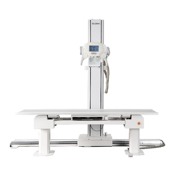
Page 15: Tube Stand
HF-525Plus Installation, Operation and Service Manual 4.4 Tube stand Function Function Description Stand can move from left to right (right to left) – longitudinal way Floor rail Stand Holding a tube and traveling Up/Down vertical way X-Ray Tube Where the X-ray does comes out LCD Display Displaying X-ray tube rotation angle and X-ray parameters. -
Page 16: Handle
HF-525Plus Installation, Operation and Service Manual 4.5 Handle Function Function Description LCD Display Display Tube’s Rotator Angle, and Controls KV, mA, sec Electrical Magnetic Functional Switch and can operate Low, High, Lock Switch Lock, All Lock, etc. Handle Use to moving Tube Device... -
Page 17: Collimator
HF-525Plus Installation, Operation and Service Manual 4.6 Collimator ■ Function of Collimator √ X-ray irradiation angle is adjusted by manual. √ Function and description of Collimator is as below. Function Function Description X-ray EXP circle Connecting to X-ray tube Window through a bracket... - Page 18 HF-525Plus Installation, Operation and Service Manual 4.7 Table Bucky ■ 4-Way Function Function Description Table top The plate where a patient can lay down for X-ray examination Bucky device Detector can travel longitudinal way for adjustment ■ 6-Way Function Function Description...
-
Page 19: Wall Bucky Stand
HF-525Plus Installation, Operation and Service Manual 4.8 Wall Bucky stand Function Function Description Bucky device Device can move Up/Down with built-in Detector Base plate Stand Bucky can be fixed with this plate into the floor. Duct port Required cables come into the duct port. -
Page 20: Ceiling Tube Support (Option)
HF-525Plus Installation, Operation and Service Manual 4.9 Ceiling Tube Support (Option) Function Function Description X-axis Rail Moving Rail Can Move Forward and Backward for Wagon Wagon Moving Column Upward and Downward and attach X-ray Tube Column This Column Moving X-ray Tube Device to Upward and to Downward Electrical Magnetic Function, and Display Tube’s Rotator Angle, and... -
Page 21: Hand Switch
HF-525Plus Installation, Operation and Service Manual 4.10 Hand Switch The HF525 Plus is equipped with a hand switch. Radiation is initiated either with the hand switch. Technical Publication Document NO: SYSTEM-007-ENG (Ver.1.1) -
Page 22: Label
HF-525Plus Installation, Operation and Service Manual 4.11 Label 4.11.1 Location The Label Attached at Main Parts’ Designated Location. √ Generator Part √ Machinery Part Technical Publication Document NO: SYSTEM-007-ENG (Ver.1.1) - Page 23 HF-525Plus Installation, Operation and Service Manual 4.11.2 Label Description Company Name, Device Model, Input Voltage, Rated Current, Serial Number, Manufacture Date, Address for European Representative, and Address for Manufacturer is on the Label. √ Generator Part √ Machinery Part Technical Publication Document NO: SYSTEM-007-ENG (Ver.1.1)
-
Page 24: Installation Of Hf-525Plus
HF-525Plus Installation, Operation and Service Manual 5. Installation of HF-525Plus 5.1 Conditions for installation Use environment Ambient environment: 10℃ to 35℃ Relative humidity : 10% to 70% (no dew condition) Atmospheric pressure: 800hPa to 1060hPa Storage environment (without a package for transport and storage) Ambient environment: -10℃... -
Page 25: Equipment Dimensions
HF-525Plus Installation, Operation and Service Manual 5.2 Equipment Dimensions 5.2.1 Generator √ Physical characteristics Size (Unit: mm) deviation ±10% Weight (Unit: Kg) Item deviation ±5 Kg Length Width Height Console Generator (Including HVT) √ Dimension (unit: mm) 5.2.2 Tube Stand √... - Page 26 HF-525Plus Installation, Operation and Service Manual It could be changeable by X-ray room size √ Dimension (unit: mm) √ From Floor to Tube Focal spot’s Minimum SID: 400mm or Less. √ From Floor to Tube Focal spot’s Maximum SID: 1900mm or Less.
- Page 27 HF-525Plus Installation, Operation and Service Manual 5.2.3 Table Bucky (4-Way) ■ Table √ Physical characteristics Size (Unit: mm) deviation ±10% Weight (Unit: Kg) Composition Deviation ±5 Kg Length Width Height Table Bucky 2,200 √ Dimension (unit: mm) ■ Bucky device √...
- Page 28 HF-525Plus Installation, Operation and Service Manual 5.2.4 Table Bucky (6-Way) ■ Table (6-way) √ Physical characteristics Size (Unit: mm) deviation ±10% Weight (Unit: Kg) Composition Deviation ±5 Kg Length Width Height Table Bucky 2,200 500~840 √ Dimension (unit: mm) √ From Floor to Table Top Minimum SID: 500mm or Less.
- Page 29 HF-525Plus Installation, Operation and Service Manual ■ Bucky device √ Physical characteristics Size (Unit: mm) deviation ±10% Weight (Unit: Kg) Composition Moving Distance From Table Deviation ±5 Kg Distance from Detector Left to Right Bucky device Max. 80 or Less √...
- Page 30 HF-525Plus Installation, Operation and Service Manual √ Moving Distance, Tube Device from Upward(Max) to Downward(Min): 1500mm or Less. Technical Publication Document NO: SYSTEM-007-ENG (Ver.1.1)
-
Page 31: Preparations For Installation
HF-525Plus Installation, Operation and Service Manual 5.3 Preparations for installation When installing the unit, prepare the following tools: √ Screw drivers and Philips screw drivers √ Hexagonal bar L-type spanners: No. 2.5~1 √ Nipper √ Pliers √ Tester √ Cutter √... - Page 32 HF-525Plus Installation, Operation and Service Manual √ Inspect the pack for evidence of shipping damage. If there is evidence of shipping damage, note this in the event that a damage claim is justified. √ Remove the wooden covers and set aside.
-
Page 33: Electrical Requirements
HF-525Plus Installation, Operation and Service Manual 5.5 Electrical requirements ■ This generator contains advanced circuitry which will maintain the selected X-ray values during irregular input voltage condition. If input voltage condition is over or less, then could not get a good X-ray radiation and have a good electric facility to be supplied with good regulation condition. -
Page 34: Fuse Capacity Of Main Parts
HF-525Plus Installation, Operation and Service Manual 5.6.1 Main wiring connection Cable length Q’ty Cable No Function Remarks (Unit: m) Three phase Depends Cable 1 power Connect line with indicated room (380VAC) Cable 2 Signal line Connect generator with console Power,... -
Page 35: Pre-Installation Checks
HF-525Plus Installation, Operation and Service Manual 5.7.1 Inter connection and grounding requirements. ■ Main line of the generator must be connecting with main electric circuit breaker. √ 415VAC 100A circuit breaker must be used. √ Connected external device with generator must have electric circuit breaker or fuse. - Page 36 ■ First, check the input voltage with tester and then connect the power cable with circuit breaker. ■ The input power must be single phase 230V AC and could check voltage with tester. CATION ▶ Only qualified (must trained by EcoRay) engineer could install this X-ray system! Technical Publication Document NO: SYSTEM-007-ENG (Ver.1.1)
-
Page 37: Installation Of Generator
HF-525Plus Installation, Operation and Service Manual 5.9 Installation of Generator 5.9.1 Appearance ■ Console ■ Generator (Front) ■ Generator (Side) 5.9.2 Consist of Main Parts ■ X-ray console connector Composition, Console (Back) Technical Publication Document NO: SYSTEM-007-ENG (Ver.1.1) - Page 38 HF-525Plus Installation, Operation and Service Manual ■ X-ray control Front ■ HVT (High Voltage Transformer)’s Upper Side ■ X-ray control Upper Side Technical Publication Document NO: SYSTEM-007-ENG (Ver.1.1)
- Page 39 HF-525Plus Installation, Operation and Service Manual 5.9.3 Function of Main Parts ■ Console √ Membrane Switches: Select and control functions. √ Console PCB: Control each function after receive signal from Membrane switches. √ External terminal: Connect Console PCB with Generator Main CPU.
- Page 40 HF-525Plus Installation, Operation and Service Manual Technical Publication Document NO: SYSTEM-007-ENG (Ver.1.1)
- Page 41 HF-525Plus Installation, Operation and Service Manual 5.9.5 Start Installation Installation procedure of X-ray generator Check serial no on the attached label with enveloped certificate’s serial no. ● Remove the generator cabinet.(Remove bolts beside of generator cover) ● Check external condition and internal cable wiring condition. If damage parts are found, order that ●...
- Page 42 HF-525Plus Installation, Operation and Service Manual 5.9.5.2 Images after installation 5.9.5.3 Generator Terminal for External Devices ■ Power Input Terminal & External Devices √ Input Power Connecting Technical Publication Document NO: SYSTEM-007-ENG (Ver.1.1)
- Page 43 HF-525Plus Installation, Operation and Service Manual √ External Devices Connecting 5.9.5.4 Manufacturer’s Instructions Prepare receptacle socket of high voltage transformer that will be installed and high voltage cable. ● (High voltage cable must be handling with always clean condition) Apply enough insulation silicon to the entire of surface of Cable plug (High voltage transformer) and ●...
- Page 44 HF-525Plus Installation, Operation and Service Manual CAUTION ▶ After wiring, adjust circuit for voltage level sensor for CnD Board. Technical Publication Document NO: SYSTEM-007-ENG (Ver.1.1)
- Page 45 HF-525Plus Installation, Operation and Service Manual 5.9.5.6 Connect High Voltage Transformer with X-ray Tube ■ Connecting HVT’s Anode, Cathode and Tube Anode, Cathode by HV Cable. ■ Connecting Cable Between GC Board’s CON703 and X-Ray Tube Anode Stator. Checking GC board CON703’s PIN ●...
- Page 46 HF-525Plus Installation, Operation and Service Manual Checking X-Ray Tube Anode Side’s Composition ● Connecting Cable between X-Ray Tube Anode Sided and GC Board CON703 ● GC board의 P805 X-Ray Tube Anode Side PIN NO P805 Wiring 1,6 PIN Stator Main 2.
- Page 47 HF-525Plus Installation, Operation and Service Manual Removing Receptacle socket Cover for Connecting HV Cable ● Applying Enough Insulation silicon oil at the End of HV Cable. ● Inserting HV Cable Plug to Receptacle socket. ● Technical Publication Document NO: SYSTEM-007-ENG (Ver.1.1)
- Page 48 HF-525Plus Installation, Operation and Service Manual After Fastening HV Cable Plug nut and Using Wrench Volt, Completely Fastening HV Cable Plug. ● WARNING ▶ The terminal pins of the high voltage cable are extremely delicate and easily damaged. And then, handle them with very carefully.
- Page 49 HF-525Plus Installation, Operation and Service Manual (1) Console I/O Board’s Composition (2) Console Backside ,and Console I/O Board’s Connector is shown below . (3) Starting to Put Cable ■ Connecting MiO Port RS232 is LAN Port and Connected by Communication Cable.
- Page 50 HF-525Plus Installation, Operation and Service Manual NOTE ▶ RS232 (Communication Cable) is connecting Generator MiO board P101 before to delivery from a factory Technical Publication Document NO: SYSTEM-007-ENG (Ver.1.1)
- Page 51 HF-525Plus Installation, Operation and Service Manual ■ Connecting Console’s SUB Port (Option) RS232 (Port) is connecting with Communication Cable. ● Tube Stand’s Handle Bar connects Board P609 and CONSOLE I/O Board’s P225 (SUB Port). ● NOTE ▶ Applying when using LCD type Handle Bar, and RS232’s communication cable is attached to Tube stand before to delivery from a factory.
- Page 52 HF-525Plus Installation, Operation and Service Manual Handle Bar Board’s Composition is shown below. ● ■ Connecting DAP Port (Option) RS232 (port) and connecting to communication cable. ● DAP meter is assembled at the end of Collimator. ● Connecting DAP meter and CONSOLE Board’s P228 (SUB) ●...
- Page 53 HF-525Plus Installation, Operation and Service Manual ■ Install ting AEC chamber (Option) RS232 (port) and connect by communication cable. ● AEC Chamber Control board can connect Three Chamber, and is composed of Table, Upright stand, ● Auxiliary. Checking AEC Chamber Attachment ●...
- Page 54 HF-525Plus Installation, Operation and Service Manual AEC Chamber Control board’s Block Diagram ● AEC Chamber Setting ● From (AEC) Chamber’S Pre-amplifier To signal to AEC Board, must be Negative. Chamber Signal is different from different manufacturers, so need to check before device Installation.
- Page 55 HF-525Plus Installation, Operation and Service Manual and, AEC Chamber’s Field Ⅰ Auxiliary Signal and Reset Reset / exposure P801, Table Signal, AEC2 stop Output signal ramp P803, Upright stand Field Ⅲ Signal, and P802 Signal all Connected. AEC2 -VDC -12V...
- Page 56 HF-525Plus Installation, Operation and Service Manual (3) Finishing Cable and Setup the Console ■ Entering by Setup mode X-Ray Console’s Reset Switch (Picture 1) and Power On Switch (Picture 2) are pushed ● simultaneously and enter OP console. ■ “PC, DAP and SUB Set”’s Set Up (Function) Entering by System setting mode, and pushing “Data Changing Switch”...
- Page 57 HF-525Plus Installation, Operation and Service Manual 5.9.6 Setup & Demo mode 5.9.6.1 Setup mode Setup mode is composed of Tube selection, Generator Limit, System setting, Console, Communication, AEC, Tube Calibration, etc. (1) X-Ray Console’s Reset Switch (Picture 1) and Power On Switch (Picture 2) are pushed simultaneously and enter OP console.
- Page 58 HF-525Plus Installation, Operation and Service Manual For Set up’s Main Function ● Console’s Switch Name Explaining Setup Function KV, mA Control Switch Changing Setup Value Data Changing Switch Changing Setup Value Tube Focal Changing Switch At Setup, choose Focal Size...
- Page 59 HF-525Plus Installation, Operation and Service Manual 5.9.6.2 Demo mode Demo mode is for exhibition such as, demonstrating generator’s function, and normally used without installation of generator usage. (1) X-Ray Console’s Reset Switch (Picture 1) and Power On Switch (Picture 2) Are Pushed Together to Enter Setup Mode.
- Page 60 HF-525Plus Installation, Operation and Service Manual 5.9.7 Generator Setup Method 5.9.7.1 Default mA Setting Default mA Setting Function is “ON”, and is displayed at LCD Display to set up, and the Default is 200mA, and Data can be changed with necessity.
- Page 61 Entering by Mode, the Screen shows Tube 1 as Default. ● HF-525Plus is for Tube 1 Device, and Tube 1 cannot be changed. ● Pushing “KV Up & Down Switch” (Picture 3), and set up to entering by Tube1 mode and make a ●...
- Page 62 Entering by Mode, the Screen shows Tube 1 as Default. ● HF-525Plus is for Tube 1 Device, and Tube 1 cannot be changed. ● Pushing “SEC Up & Down Switch” (Picture 2), and set up to entering by KW (Picture 4).
- Page 63 Entering by Mode, the Window / Screen shows Tube 1 as Default. ● HF-525Plus is for Tube 1 Device, and Tube 1 cannot be changed. ● Pushing “KV Up & Down Switch” (Picture 3) to set up KV min (Picture 5).
- Page 64 Entering by Mode, the Window / Screen shows Tube 1 as Default. ● HF-525Plus is for Tube 1 Device, and Tube 1 cannot be changed. ● Pushing “KV Up & Down Switch” (Picture 3) to set up KV min (Picture 5).
- Page 65 Entering by Mode, the Window / Screen shows Tube 1 as Default. ● HF-525Plus is for Tube 1 Device, and Tube 1 cannot be changed. ● Pushing “Sec Up & Down Switch” (Picture 2) to set up mAs Limit. (Picture4).
- Page 66 HF-525Plus Installation, Operation and Service Manual ■ Bucky type set (1) Set up Table Bucky’s Bucky type, Set, and Time. . Entering by System setting mode, and pushing “Changing Data Switch” (Picture 1), and entering by ● “Bucky Type set” mode (Picture7) Pushing “F2”...
- Page 67 Default Setting Up Data Over Load Parameter NOTE ▶ Over Load Parameter (Set up Pupose), Ecoray tested this parameter data numerous time, so should not be changed. ■ Ready time set Entering by System setting mode, and pushing “Changing Data Switch” (Picture 1), and entering by ●...
- Page 68 At Delivery from a factory, the Default Data is shown below. ● Device Default로 Setting Up Data Ready time 2000 NOTE ▶ Ready time Set up (Purpose), Ecoray tested this parameter data numerous time, so should not be changed. Technical Publication Document NO: SYSTEM-007-ENG (Ver.1.1)
- Page 69 .Entering by Mode, the Window / Screen shows Tube 1 as Default. ● HF-525Plus is for Tube 1 Device, and Tube 1 cannot be changed. ● . Pushing “mA Up & Down Switch” Switch (Picture2) and set up Small focal’s Focal Edge (Picture 4).
- Page 70 Changed Data can saved using Memory “M” Switch (Picture 5) and pushed until “Beep” ends. ● (Buzzer occurs 10 seconds). (2) ABC mode does not support HF-525Plus ■ R&F REMOTE mode set R&F REMOTE mode does not support HF-525Plus ■ Pulse mode set Pulse mode does not support HF-525Plus.
- Page 71 HF-525Plus Installation, Operation and Service Manual ■ 1 Ready Expo set Entering by System setting mode, and pushing “Changing Data Switch” (Picture 1), and entering by ● “AEC and ABC set” mode (Picture 4) Pushing “mA Up & Down Switch” (Picture2) to select Exposure Type (Picture 4).
-
Page 72: Installation Of Tube Stand
HF-525Plus Installation, Operation and Service Manual 5.10 Installation of Tube stand 5.10.1 Appearance ■ Floor Rail ■ Stand Technical Publication Document NO: SYSTEM-007-ENG (Ver.1.1) - Page 73 HF-525Plus Installation, Operation and Service Manual 5.10.2 Consist of Main Parts ■ Floor Rail & Stand ■ Handle Bar & Tube Arm Technical Publication Document NO: SYSTEM-007-ENG (Ver.1.1)
- Page 74 HF-525Plus Installation, Operation and Service Manual 5.10.3 Function of Main Parts ■ Stand √ Column: Device helps the X-ray tube travelling up & down. √ Vertical move device: holding X-ray tube and to be connected to Tube Stand to support up & down travel.
- Page 75 HF-525Plus Installation, Operation and Service Manual 5.10.5 Start Installation Installation procedure of Tube Stand Check if the serial No. on the label is match with the serial No. on the quality certificate. ● During the unpacking, check if all the devices are in well condition, especially at cables. In case any ●...
- Page 76 HF-525Plus Installation, Operation and Service Manual 5.10.5.2 Stand installation. Put the Stand on the floor rail carrier (please see the photo below) ● Fix the Stand into Carrier with fixing bolts. ● CAUTION ▶ 3 persons are required to do this job.
- Page 77 HF-525Plus Installation, Operation and Service Manual 5.10.5.3 X-ray tube assembly Locate the Tube Arm to appropriate position for X-ray tube assembly. ● Put X-ray tube on Tube York– at this time, please insert weight balance plates into behind of Tube ●...
- Page 78 HF-525Plus Installation, Operation and Service Manual 5.10.5.4 Understanding Wiring ■ Checking Tube Stand’s Connector TS-IO-1 Connector & Generator GC Board’s P850, P976’s Wiring Cable. Upper Side, Generator PIN NO P805 (Rotor) P976 AC21V AC 0V (COM) AC21V AC 0V (COM)
- Page 79 HF-525Plus Installation, Operation and Service Manual ■ Checking Tube Stand’s Handle bar Connector TS-HD-IO-2 Connector & Generator MiO Board’sP804’s Wiring Cable. Upper Side, Generator PIN NO P805 (Rotor) P976 AC21V AC 0V (COM) AC21V AC 0V (COM) Emergency SW Emergency SW Tube Temp.
- Page 80 HF-525Plus Installation, Operation and Service Manual 5.10.5.5 Wiring Tube Stand and Generator ■ Picture 1: Wiring cables from Tube Stand’s Connector TS-IO-1 Connector to Generator GC Board’s P850, P976. ■ Picture 2: Wiring Cables from Tube Stand’s Handle bar Connector to TS-HD-IO-2 Connector and Generator MiO Board’s P804.
- Page 81 HF-525Plus Installation, Operation and Service Manual 5.10.5.6 Handle bar (LCD module) Cable connection There are ports like Generator cable, Angle sensor port, Power port. ● Connect LCD Module first. ● Make correct wiring to LCD Module. ● No.1: P609 in Handle Bar PCB goes to OP console SUB port.
- Page 82 HF-525Plus Installation, Operation and Service Manual Make correct wiring to LCD Module. ● Technical Publication Document NO: SYSTEM-007-ENG (Ver.1.1)
- Page 83 HF-525Plus Installation, Operation and Service Manual 5.10.5.7 Lock cabling Left/Right, Column Rotation, Tube Rotation Lock Locker are Up/ Down, Front/Rear, ● Please pay your attention to the Lock board location – see below photo. ● Make correct cabling for Tube Rotation Lock, Front/Rear Lock.
- Page 84 HF-525Plus Installation, Operation and Service Manual (1) Complete the wiring between A and B. No.1: Connection between AC3 (Handle Bar Power) and P914 on Stand Lock Board. No.2: Connection between P910 on Lock board and Front/Rear Lock. Tube Rotation Lock No.3: Connection between P913 in Stand Lock Board and...
- Page 85 HF-525Plus Installation, Operation and Service Manual ● Up/ Down, Left/Right Lock cablings. (1) Make wiring through Connecting hole lead line. Left/Right No.1: Connection between P911 on Stand Lock Board and Lock. No.2:Connection between P915 on Stand Lock Board and Up/ Down Lock.
- Page 86 HF-525Plus Installation, Operation and Service Manual Make proper wiring on Tube Anode side. ● No.1: Tube Anode side cables must go to Generator GC Board P976 Technical Publication Document NO: SYSTEM-007-ENG (Ver.1.1)
- Page 87 HF-525Plus Installation, Operation and Service Manual ■ Wiring Cable, Generator GC board & Collimator. P976 of GC Board Anode side of X-ray Tube (Upper side of Generator) Stator Com (SC1) Stator Com (SC1) Stator Main(SM1) Stator Main(SM1) Technical Publication Document NO: SYSTEM-007-ENG (Ver.1.1)
-
Page 88: Installation Of Ceiling Tube Support
HF-525Plus Installation, Operation and Service Manual 5.11 Installation of Ceiling tube support 5.11.1 Appearance ■ Side ■ Front Technical Publication Document NO: SYSTEM-007-ENG (Ver.1.1) -
Page 89: Functions Of Main Components
HF-525Plus Installation, Operation and Service Manual 5.11.2 Consist of Main Parts ■ Wagon ■ Handle Bar & Tube Arm Functions of main components ■ Wagon √ Carry the device to the right position. √ Make the horizontal & vertical balance. - Page 90 HF-525Plus Installation, Operation and Service Manual √ Fix the device with Wedge Anchor bolt.. ■ Rail √ Cassette Tray locates cassette √ Cassette holder is a fixture that does not move the cassette. √ Grid is a lattice to get rid of scattered X-ray.
- Page 91 HF-525Plus Installation, Operation and Service Manual 5.11.4 Start Installation Installation procedure of Ceiling tube support Check if the serial No. on the label is match with the serial No. on the quality certificate. ● During the unpacking, check if all the devices are in well condition, especially at cables. In case any ●...
- Page 92 ● entire Long rail…the static position and hardness is very important!! (see photo below) NOTE ▶ ECORAY does not provide this ceiling frame!!! The Check each location like this drawing. ● Bracket for long rail is well installed on the ceiling frame.
- Page 93 HF-525Plus Installation, Operation and Service Manual 5.11.4.2 Long rail (X-axis) Installation Complete Long Rail and measure its width. ● And dismantle the rail to make separate rail frames of 1,2,3 and 4 like below photo. ● Technical Publication Document NO: SYSTEM-007-ENG (Ver.1.1)
- Page 94 HF-525Plus Installation, Operation and Service Manual Separated long rails to be installed at ceiling frame. ● Long rail to ceiling frame ● Technical Publication Document NO: SYSTEM-007-ENG (Ver.1.1)
- Page 95 HF-525Plus Installation, Operation and Service Manual The long rails are joined to ceiling frame (see below photo) ● Technical Publication Document NO: SYSTEM-007-ENG (Ver.1.1)
- Page 96 HF-525Plus Installation, Operation and Service Manual Once the stopper is installed, then measure the distance between 2 long rails. (see below photo) ● CAUTION ▶ When 2 side distance is same, you can join the bolts tight enough. Technical Publication Document NO: SYSTEM-007-ENG (Ver.1.1)
- Page 97 HF-525Plus Installation, Operation and Service Manual 5.11.4.3 Lower rail (Y-axis) Installation Check and compare long rail width distance and short rail width. ● Measuring at short rail, you can check from the outside of bearings. ● If there is any deviation, just adjust it by moving short rail bearing plate position.
- Page 98 HF-525Plus Installation, Operation and Service Manual When you insert the rail, please pay your attention to Main bearing (bigger one, upper side) and ● Guide bearing (lower side smaller one). 5.11.4.4 LONG rail (X-axis) Cover assembly Install stoppers at each end of rails. (Total 4 stoppers) ●...
- Page 99 HF-525Plus Installation, Operation and Service Manual Check and verify the stopper position again ● Cover close. ● 5.11.4.5 Wagon (ceiling unit) installation Remove Short rail stoppers from the rails. ● And insert ceiling unit into the slot.. (Bearing docking) ●...
- Page 100 HF-525Plus Installation, Operation and Service Manual CAUTION ▶ This ceiling unit is very heavy (over 150kg), so you need a specialized lift or 5+ people to lift it up together. Be careful not to have any safety issue – possible to meet accident during the lift because the unit must be installed at overhead height..!!!
- Page 101 HF-525Plus Installation, Operation and Service Manual Unscrew the bolts on Wagon Column. ● Install Tube holder into the Wagon Column. ● Technical Publication Document NO: SYSTEM-007-ENG (Ver.1.1)
- Page 102 HF-525Plus Installation, Operation and Service Manual Technical Publication Document NO: SYSTEM-007-ENG (Ver.1.1)
- Page 103 HF-525Plus Installation, Operation and Service Manual Spring balance (yellow color module) pin check ● Make Spring Balance pin position at LOCK FREE ● At Lock free condition, you can scroll the column down to appropriated height for tube assembly. ●...
- Page 104 HF-525Plus Installation, Operation and Service Manual And when the height is fixed, lock it up to hold it at the position. ● Remove upper Yoke – this will be installed again with Tube later. ● Technical Publication Document NO: SYSTEM-007-ENG (Ver.1.1)
- Page 105 HF-525Plus Installation, Operation and Service Manual Check balance of this tube holder. ● If balance needs to be adjusted, please unscrew the side bolts and shift the holder for perfect ● balance. (and join the bolts tight when the balance it good)
- Page 106 HF-525Plus Installation, Operation and Service Manual When the balance is good, put Tube on the position and cover the upper Yoke then join the tube ● angle fixing bolts. Turn the tube up-side down to install lower cover. ● Technical Publication Document NO: SYSTEM-007-ENG (Ver.1.1)
- Page 107 HF-525Plus Installation, Operation and Service Manual And fix the bottom cover. ● Check the collimator components like bolts and plates. (Please see the photo below). ● Technical Publication Document NO: SYSTEM-007-ENG (Ver.1.1)
- Page 108 HF-525Plus Installation, Operation and Service Manual Before collimator module installation, please put AL filter first and bracket then insert collimator ring ● with screws. Now put collimator on it and join the bolts to fix it. ● Collimator is on the position now. (Turn the tube to normal position) ●...
- Page 109 HF-525Plus Installation, Operation and Service Manual Technical Publication Document NO: SYSTEM-007-ENG (Ver.1.1)
- Page 110 HF-525Plus Installation, Operation and Service Manual 5.11.4.7 Understanding Wiring ■Checking the Wiring from Tube Stand’s Connector TS-IO-1 Connector to Generator GC Board’s P850, P976. Upper Side, Generator PIN NO P805 (Rotor) P976 AC21V AC 0V (COM) AC21V AC 0V (COM)
- Page 111 HF-525Plus Installation, Operation and Service Manual ■ Checking the wiring from Tube Stand’s Handle bar Connector TS-HD-IO-2 Connector to Generator MiO Board. Upper Side, Generator PIN NO P805 (Rotor) P976 AC21V AC 0V (COM) AC21V AC 0V (COM) Emergency SW Emergency SW Tube Temp.
- Page 112 HF-525Plus Installation, Operation and Service Manual 5.11.4.8 Understanding Wiring Tube Stand and Generator ■ Wiring Generator GC board and Handle bar. P976 of GC Board Anode side of X-ray Tube (Upper side of Generator) Stator Com (SC1) Stator Com (SC1)
- Page 113 HF-525Plus Installation, Operation and Service Manual 5.11.4.9 Cabling Ceiling First connect Power cable and Bucky signal cab ● No.1: Ceiling powerl is coming from Generator GC Board P976 Wiring Upright stand and Generator GC Board’s P807. ● Check and prepare for communication cable, magnetic lock cables well like the photo below.
- Page 114 HF-525Plus Installation, Operation and Service Manual Tube Anode side cables to be prepared. ● Make correct wire position on anode side. (The location of each wire is important!!) ● Technical Publication Document NO: SYSTEM-007-ENG (Ver.1.1)
- Page 115 HF-525Plus Installation, Operation and Service Manual Prepare Handle Bar wires and connect them on positions. ● Tube Anode side cables to be prepared. ● Technical Publication Document NO: SYSTEM-007-ENG (Ver.1.1)
- Page 116 HF-525Plus Installation, Operation and Service Manual Close the cover when the cabling is completed. ● Generator cable and console Sub connector. ● Handle Bar Cabling and Tube anode cabling and its order. ● (1) Use Bracket 1 for cabling Technical Publication Document NO: SYSTEM-007-ENG (Ver.1.1)
- Page 117 HF-525Plus Installation, Operation and Service Manual (2) Use Bracket 2 for cabling. Technical Publication Document NO: SYSTEM-007-ENG (Ver.1.1)
- Page 118 HF-525Plus Installation, Operation and Service Manual 5.11.4.10 Cover assembly Cable guide sub assembly ● BAND Connection ● Technical Publication Document NO: SYSTEM-007-ENG (Ver.1.1)
- Page 119 HF-525Plus Installation, Operation and Service Manual Wagon Cover close ● √ Install bracket for rear cover. (Wagon rear side) √ Install front side cover bracket. (Front Wagon) Technical Publication Document NO: SYSTEM-007-ENG (Ver.1.1)
- Page 120 HF-525Plus Installation, Operation and Service Manual √ And join the bolts on the brackets. √ Now install plastic cover for Front and Rear ones. Technical Publication Document NO: SYSTEM-007-ENG (Ver.1.1)
-
Page 121: Installation Of Table Bucky
HF-525Plus Installation, Operation and Service Manual 5.12 Installation of Table Bucky 5.12.1 Appearance BT Picture Change ■ Table ■ Bucky Device Technical Publication Document NO: SYSTEM-007-ENG (Ver.1.1) - Page 122 HF-525Plus Installation, Operation and Service Manual 5.12.2 Consist of Main Parts ■ Table ■ Bucky Device Technical Publication Document NO: SYSTEM-007-ENG (Ver.1.1)
- Page 123 HF-525Plus Installation, Operation and Service Manual 5.12.3 Consist of Main Part ■ Table √ Bucky device restrains scattered X-ray. √ Foot switch controls upper table which is fixed with electromagnet. √ Fixture plate settles the product on the floor after the installation.
-
Page 124: Start Installation
HF-525Plus Installation, Operation and Service Manual 5.12.5 Start Installation Installation procedure of Table Bucky Identify a label on the product with serial number of test report that included in package. ● If user finds out any harm of damage on external appearance or internal wiring, user should order ●... - Page 125 HF-525Plus Installation, Operation and Service Manual 1. After horizontal confirmation, user fix the table. (See the picture) 2. Fixture of patient table is performed for certain. (See the below picture) 5.12.5.2 Understanding Wiring ■ Checking the Wiring to Table Bucky Board’s TCON2 Connector and Generator GC Board’s P807.
- Page 126 HF-525Plus Installation, Operation and Service Manual Bucky COM Bucky OUT AC 220V AV 220V COM 5.12.5.3 Wiring Table Bucky Power supply Power supplies from generator and it should be pre-check its voltage with voltage meter. ● The power supplied to tube stand is 24VDC and the voltage could be checked with voltage meter.
- Page 127 HF-525Plus Installation, Operation and Service Manual Wiring Table Bucky Board and Generator GC Board. ● Technical Publication Document NO: SYSTEM-007-ENG (Ver.1.1)
-
Page 128: Installation Of Wall Bucky Stand
HF-525Plus Installation, Operation and Service Manual 5.13 Installation of Wall Bucky Stand 5.13.1 Appearance ■ Stand ■ Bucky Device Technical Publication Document NO: SYSTEM-007-ENG (Ver.1.1) - Page 129 HF-525Plus Installation, Operation and Service Manual 5.13.2 Consist of Main Parts ■ Table ■ Bucky Device 5.13.3 Consist of Main Part ■ Stand √ Bucky device: Bucky is a device that moves the grid while x-ray is being taken. √ Electro-magnetic fixing switch: Use this device when you move bucky device up and down √...
- Page 130 HF-525Plus Installation, Operation and Service Manual √ Cassette holder is a fixture that does not move the cassette. √ Grid is a lattice to get rid of scattered X-ray. √ Oscillator moves grid right and left. √ Ion Chamber controls exposure time automatically.
- Page 131 HF-525Plus Installation, Operation and Service Manual 5.13.4.2 Understanding Wiring ■ Checking wiring to Table Bucky Board’s TCON2 Connector and Generator GC Board’s P807. Upper Side, Generator IN NO P807 AC 0V Technical Publication Document NO: SYSTEM-007-ENG (Ver.1.1)
- Page 132 HF-525Plus Installation, Operation and Service Manual AC 23V Bucky COM Bucky OUT AC 220V AV 220V COM 5.13.4.5 Cabling Wall Bucky Stand Power input ● √ Power is supplied by generator and check the voltage with voltmeter before supplying power √...
- Page 133 HF-525Plus Installation, Operation and Service Manual Wiring Upright stand & Generator GC Board’s P807. ● Technical Publication Document NO: SYSTEM-007-ENG (Ver.1.1)
-
Page 134: System Cable Wiring Check
HF-525Plus Installation, Operation and Service Manual 5.14 System Cable Wiring Check ① ⑤ X-ray Tube ECO-XR5-HANDLE Board (Handle bar of Tube Support) Electromagnetic lock for Tube rotation ECO-XR5-GC Board (Upper side of Generator WARNING ▶ If do not use Door and EMG functions, then never remove the attached pin of tube support connector pin (Door and EMG). - Page 135 HF-525Plus Installation, Operation and Service Manual X-Axis Bracket Y-Axis Bracket Tube Device Upright Sensor Bracket Upright Downward Bucky Table Connector Box Position Sensor Bracket Technical Publication Document NO: SYSTEM-007-ENG (Ver.1.1)
-
Page 136: Calibration
Installation, Operation and Service Manual 6 Calibration 6.1 Generator Calibration 6.1.1 Overview This Generator calibration must be performed only by the calibration software program of Ecoray. Characteristics of calibration software program The calibration software program is operated on PC. ●... - Page 137 HF-525Plus Installation, Operation and Service Manual 6.1.4 When to do calibration When to do What to do Remarks After product installation, Calibration for X-ray Refer to the chapter 4 including relocation exposure parameters Periodic testing for maintenance Calibration for X-ray...
- Page 138 HF-525Plus Installation, Operation and Service Manual Click “Hardware”, then click “OK”. ● Click “Device Manager”, then click “OK”. ● Technical Publication Document NO: SYSTEM-007-ENG (Ver.1.1)
- Page 139 HF-525Plus Installation, Operation and Service Manual Click “Communications Port(COM1)”, then click “Port Settings”. ● Check the selected values. ● Click “Advanced”, then click “OK”. ● Technical Publication Document NO: SYSTEM-007-ENG (Ver.1.1)
- Page 140 HF-525Plus Installation, Operation and Service Manual On the displayed “Advanced Setting for COM1”, select “Use FIFO buffers(requires 16550 compatible ● UART)”. Select a suitable one from COM1 to COM5, then click “OK”. ● Installation of “USB to RS232 Converter Driver” is finished ●...
-
Page 141: Installation Of Calibration Software Program
Insert the CD for calibration software program into PC. ● Click “My Computer” icon from the wallpaper. ● On the “Devices with Removable Storage” pane, double click “EcoRay Calibrate”. ● On the “Calibrate” pane, copy “Calibrate”. ● Move the “Calibrate” on the wallpaper. - Page 142 HF-525Plus Installation, Operation and Service Manual On the “Setup” pane, click “auto run” file. ● Click “OK” button. ● Installation of calibration software program is finished. Technical Publication Document NO: SYSTEM-007-ENG (Ver.1.1)
-
Page 143: Preparations For The Calibration
6.3.2 USB cable for “USB to RS232 Converter” This USB cable is generally available ● 6.3.3 Gender for the connection of generator This gender is made by Ecoray. ● 6.3.4 Connection of the communication cable Connection between the RS232 Port and USB Port of PC. -
Page 144: Program Execution For Calibration
HF-525Plus Installation, Operation and Service Manual 6.4 Program execution for calibration 6.4.1 Program execution of “Ecoray_Calibrator” On the wallpaper, double click “Calibrate”. ● On the “Calibrate” pane, click “Program”. ● On the “Program” pane, click “Ecoray_Calibrator” file. ● Technical Publication Document NO: SYSTEM-007-ENG (Ver.1.1) - Page 145 HF-525Plus Installation, Operation and Service Manual Then, it will be displayed as the following: ● Technical Publication Document NO: SYSTEM-007-ENG (Ver.1.1)
- Page 146 HF-525Plus Installation, Operation and Service Manual 6.4.2 Selection of the communication port Click “Port Check”, and confirm that the selected communication port is a suitable one from COM1 to ● COM5. If the communication port is selected in normal range, click “Power ON”.
-
Page 147: Program Functions
HF-525Plus Installation, Operation and Service Manual 6.5 Program functions Operation, Setup, Calibration Window Part 6.5.1 Operation Part Possible select X-ray exposure parameters (e.g. kV, mA and selection of X-ray tube). ● Technical Publication Document NO: SYSTEM-007-ENG (Ver.1.1) - Page 148 HF-525Plus Installation, Operation and Service Manual Functions Description of functions Saving and output the calibration data. Saving data (This function is only used in the manufacturing process) Selection of communication Selection of communication port between PC and port calibration program.
- Page 149 HF-525Plus Installation, Operation and Service Manual 6.5.2 Setup Part Possible select the capacity of generator and the filament preheat voltage. ● Functions Description of functions Selection of bucky function Selection of each bucky operating mode. Indication of product failure Indication of product failure and description.
-
Page 150: Calibration Of Radiography
HF-525Plus Installation, Operation and Service Manual Functions Description of functions Indication of X-ray tube, Indication of the location and focal spot of X-ray tube which is focal spot selected on the setup part. Indication of kV Indication of the kV range which is selected on the setup part. - Page 151 HF-525Plus Installation, Operation and Service Manual 6.6.2 Selection of capacity of generator Select min. and max. kV on the “Small Focal (S.kV)” (see No 1of the above fig). ● Select min. and max. kV on the “Large Focal (L.KV)” (see No 1of the above fig).
- Page 152 HF-525Plus Installation, Operation and Service Manual Year Mont Identification The indication of “No 2” is only used in the manufacturing process (see No 2of the above fig). ● The “Slice” indicates the number of X-ray exposures (see No 3of the above fig).
- Page 153 HF-525Plus Installation, Operation and Service Manual 6.6.4 System Check The indication of “No 1” indicates the state of product (see No 1of the above fig). ● When the failure is detected, red indicator is lighting. ● When the red indicator is lighting, do not operating X-ray exposure.
- Page 154 HF-525Plus Installation, Operation and Service Manual Click “Calibration On/Off”(see No 1of the above fig). ● The “System State” indicates “Now Data Access” (see No 5 of the above fig). ● When it indicates“Now Data Access”, the calibration data of MiO board move to a calibration program ●...
-
Page 155: Start Calibration
HF-525Plus Installation, Operation and Service Manual 6.6.6 Start calibration Install equipments for calibration. (Refer 3 of this chapter) ● Execute “Calibration window”. ● 6.6.7 Selection of X-ray tube and small focal Select a suitable X-ray tube and small focal. ●... -
Page 156: Sequence Of Calibration For Radiographic Mode
HF-525Plus Installation, Operation and Service Manual 6.7 Sequence of calibration for radiographic mode 6.7.1 Selection of kV, mA for calibration kV: 40, 60, 80, 100, 125 ● Small focal: 10, 25, 50, 75, 100mA ● Large Focal: 150mA ● 6.7.2 Sequence of calibration for small focal Sequence of calibration, in case of small focal at 40 kV Select 40 kV→... - Page 157 HF-525Plus Installation, Operation and Service Manual meter → Change data, if necessary→ Click “Enter” on keyboard For sequence of calibration at 60, 80, 100, 125, 150 kV, perform the same sequence at 40 kV. 6.7.4 Flow diagram for sequence of calibration 6.7.5 Confirmation of dose after calibration...
- Page 158 HF-525Plus Installation, Operation and Service Manual Select “Radio or Fluor” on ● “Tube Select” (see No 1of the above fig). ● Execute “X-ray exposure”. ● NOTE▶ Under pushing “Ctrl” on keyboard for “Ready”, pushing “X” on keyboard for “X-ray exposure”...
-
Page 159: Introduction And Using Method
Installation, Operation and Service Manual 7. Introduction and Using Method 7.1 Introduction 7.1.1 An Overview This HF-525Plus manual contains of operation, safety and specification of this X-ray system. ● This X-ray system was developed by high frequency inverter circuit base. ●... - Page 160 HF-525Plus Installation, Operation and Service Manual ■ Rear view Function Function Description Power ON/Off On or Off the generator. Resets error condition when it appears. (the errors come from main Reset Switch CPU) Rotor condition display Shows Tube Rotation condition (Low or High Speed) APR selection button Patient body part selection to recall saved data of X-ray dose.
- Page 161 HF-525Plus Installation, Operation and Service Manual 7.2.3 Power ON Make sure the Standby LED is ON. (See the pic below, normal status is Orange color) ● Press ON button to turn on the generator. ● When Power ON button is press, Standby LED is flickering for 20 sec and finally LED on with green ●...
- Page 162 HF-525Plus Installation, Operation and Service Manual Technical Publication Document NO: SYSTEM-007-ENG (Ver.1.1)
- Page 163 HF-525Plus Installation, Operation and Service Manual 7.2.4 Membrane Key display and functions Name Icon Function Power ON. Power ON / Off Switch Power off. Make the generator RESET when any error stop or Reset Switch abnormal display is appeared. Anode Speed = Low Speed...
- Page 164 HF-525Plus Installation, Operation and Service Manual Recall patients’ body parts from CPU Memory in APR selection where it has X-ray exposure data for Skull, Chest, Abdomen, Hand, Foot, Aux etc. Can select if you will use DAP function or not. (LED on DAP Chamber ON/Off is function selected.
- Page 165 HF-525Plus Installation, Operation and Service Manual Adjust kV value here. (from 40 to 125) changing fast KV control with FAST key together. Adjust mA value here (from 10 to max. 1000mA) Max. mA control mA is different from generator specification.
- Page 166 HF-525Plus Installation, Operation and Service Manual Select Bucky location like NO Bucky, Table Bucky, Wall Bucky Stand. Sub body part selection in APR Select direction of exam in APR (AP, PA, LAT and OBL) 7.2.5 How to use APR (Anatomical Programmable Radiography) function.
- Page 167 HF-525Plus Installation, Operation and Service Manual Large size (adults) Extra selection (if required, please program it) No.3 ● (1) Sub body part selection. (2) Main body part should be selected first. (3) F3 can change to select, and icons are appearing on the screen.
- Page 168 HF-525Plus Installation, Operation and Service Manual When the main body part (Chest) is selected, press F3 to find ‘Sternum view’ and the icon appears on LCD screen. Select ‘Chest’ in top menu, and press F3 to fix it at ‘AUX2’...
- Page 169 HF-525Plus Installation, Operation and Service Manual With Abdomen selected, press F3 to select at ‘Pelvis’ then its body part appears on LCD screen. With Abdomen selected, press F3 to select at ‘Hop None’ then its body part appears on LCD screen.
- Page 170 HF-525Plus Installation, Operation and Service Manual With Foot selected, press F3 to select at ‘Tibia’ then its body part appears on LCD screen. With Foot selected, press F3 to select at ‘Knee’ then its body part appears on LCD screen.
-
Page 171: Cassette Tray
HF-525Plus Installation, Operation and Service Manual 7.2.6 How to select Bucky Bucky is selectable from OP console as Table Bucky, Stand Bucky. ■ How to select No.1 ● (1) Select desired Bucky. (2) Two Buckys are selectable, Table Bucky, Wall Bucky Stand. - Page 172 HF-525Plus Installation, Operation and Service Manual ● AEC Chamber (Optional) (1) AEC chamber is in the bucky device – for Automatic Exposure Control. ● Cassette tray (1) Bucky device is locked by EMB (electromagnetic breaker) when the system is power ON. You can release it by a button beside of bucky handle.
- Page 173 HF-525Plus Installation, Operation and Service Manual 7.2.7 How to save desired X-Ray value set The X-ray value set can be saved to each Bucky (Table Bucky, Stand Bucky). X-Ray set is composed of kV, mA, sec and the values are appearing on LCD screen.
- Page 174 HF-525Plus Installation, Operation and Service Manual Console SETUP mode can define the AEC function details. (only Eng mode) No.1 ● (1) AEC ON/OFF (activate or deactivate it) . (2) The button’s LED is ON when activated. No.2 ● (1) Select chamber (sensor) activation, there are 3 sensors in each AEC chamber and the buttons can select each sensor ON/OFF.
- Page 175 HF-525Plus Installation, Operation and Service Manual NOTE▶ DAP setup is available in Setup mode (Eng mode) that Chap.5 introduces . No.1 ● (1) DAP ON or OFF button, LED is ON when activated. (another press will deactivate it) No.2 ●...
-
Page 176: X-Ray Exposure
HF-525Plus Installation, Operation and Service Manual (6) When generator is in trouble with power, Standby LED turns ‘yellow’ and LCD screen will alert with error message. (7) Users can make Reset and try to power ON the generator again. NOTE▶... -
Page 177: How To Use Tube Stand Handle Bar
HF-525Plus Installation, Operation and Service Manual CAUTION ▶ If you press the Ready switch (Figure 4) on the console and then release the Ready switch (Figure 4) while the Ready is in progress, X-ray shooting will stop. So, be careful to press both Ready and X-ray buttons at the same time without releasing your hand. - Page 178 HF-525Plus Installation, Operation and Service Manual Figure1 ● (1) The LCD display (Figure 1) displays the X-ray irradiation condition set in the X-ray console and the rotation angle of the X-ray tube. (See LCD display window of 7.3.1 Handle bar) Figure2 ●...
- Page 179 HF-525Plus Installation, Operation and Service Manual 7.3.3 Collimator The collimator is a device that adjusts the X-ray to expose only the part of the patient's body that is absolutely necessary to prevent the patient from being unnecessarily exposed to the X-ray when the X-ray is taken.
- Page 180 HF-525Plus Installation, Operation and Service Manual Collimator movement ● (1) Move the tube stand to the patient's X-ray exposure point. (2) The minimum distance between the Tube Focal and Detector surface should be at least 100 cm. (3) The distance between the Tube Focal and the patient should be as long as possible.
-
Page 181: Starting And Shutting Down The System
HF-525Plus Installation, Operation and Service Manual 8 Starting and Shutting Down the System 8.1 Preparing for the X-ray System Operation ■ Check the voltage to be supplied to the X-ray system. ■ Connect the power to the X-ray system. ■ The following should be checked before X-ray system operation. -
Page 182: Power Off
HF-525Plus Installation, Operation and Service Manual 8.2.2 Power Off ■ To turn off the X-ray system, press the Power Switch on the console to Power “Off”. ■ Activating the console's Power “Off” switch will stop the x-ray system operation at the same time. -
Page 183: Emergency Switch Operation
HF-525Plus Installation, Operation and Service Manual 8.3 EMERGENCY Switch operation 8.3.1 Power Off ■ In case of emergency, press the Emergency switch on the side of the Table Buckle to shut off the power. If an emergency occurs during system operation, turn off the power by pressing the Emergency ●... - Page 184 HF-525Plus Installation, Operation and Service Manual √ Check whether the x-ray system is activated after the console "Power On". √ Check that the console's Standby Lamp is on. (Normal: yellow) √ Check if the Waiting Lamp turns off when the console's power is "ON". (Normal: Off) √...
-
Page 185: Specification
HF-525Plus Installation, Operation and Service Manual 9 Specification 9.1 Operator's Console Type Microprocessor control & Digital display Indication meter kV, mA, mAs or msec mA setting 10mA to 500mA (±5%) kV setting 40kV to 125KV (±5%) Time setting 10msec ~ 6.3sec... -
Page 186: Tube Stand
HF-525Plus Installation, Operation and Service Manual Model E7239X Nominal Tube Voltage 40 to 125kVp Max. (Radiographic) Anode heat storage 140,000HU Nominal Focal Spot Value Small: 1.0mm, Large: 2.0mm Construction Rhenium-Tungsten faced Molybdenum Target angle 16° Permanent filtration 0.9mmAl/75KV IEC 60522/2003 Weight Approx. - Page 187 HF-525Plus Installation, Operation and Service Manual Added Filtration 0.8mm Al Maximum X-ray Field size Below 5cm x 5cm at SID 100cm Minimum X-ray Field size Below 35cm x 35cm at SID 65cm Light projection More than 160lux at SID 100Cm Lamp timer Approx.
-
Page 188: Wall Bucky Stand
HF-525Plus Installation, Operation and Service Manual Grid specification Ratio: 10:1, 103lines/inch X-ray IMAGE RECEPTOR Film cassette OR DR Detector Cassette loading From front side Tabletop locking Electromagnetic lock by optical sensor Dimension Approx. 2,200 x 700 x 700mm Weight 140Kg... -
Page 189: Dap(Dose Area Product) Meter (Optional)
HF-525Plus Installation, Operation and Service Manual Longitudinal, transverse lock Electromagnetic lock and release Counterbalance system Spring balancer Over 100㎝ (Distance between director and tube focal) Minimum ceiling height Approx. 2,700mm Weight Approx. 135kg (without rail) 9.11 DAP(Dose Area Product) meter... -
Page 190: Maintenance
HF-525Plus Installation, Operation and Service Manual 10 Maintenance 10.1 An Overview HF-525 Plus requires maintenance of the X-ray system regularly and periodically to maintain the performance and functionality of the X-ray system. Therefore, users of X-ray system should prepare X-ray system maintenance plan and execute X-ray system maintenance regularly and periodically. -
Page 191: X-Ray System Cleaning
HF-525Plus Installation, Operation and Service Manual has been trained in technical training, asking the dealer or the manufacturer for inspection. 10.5 X-ray system cleaning 10.5.1 X-ray system Exterior Cleaning ■ X-ray system exterior cleaning is done by the X-ray system user. -
Page 192: Main Parts List
HF-525Plus Installation, Operation and Service Manual ■ Check the supplied voltage to the generator. ■ Check the supplied voltage to the main board. ■ Check the internal parts of the generator and check for noise, heat, and smell. ■ Check the assembled parts of the generator. -
Page 193: Error Code
HF-525Plus Installation, Operation and Service Manual 11 Error Code 11.1 Error Type, Display and Error state Error type Cause 1. Charging to Main Capacity is not normal. Charge Circuit 2. Input voltage is out of boundary. (Too high or too low) problem (Standard input voltage: Single phase, 230VAC ±10%) -
Page 194: Introduction
HF-525Plus Installation, Operation and Service Manual 12.1 Introduction HF-525 Plus monitors the Generator fault status in real-time electrical circuit and sends the fault information to the Console when the X-ray system fails display the fault information on the display window. The fault status is organized by Error Code and provides a solution to repair X-ray system user or service person in order to easily solve the faulty part of X-ray system. - Page 195 HF-525Plus Installation, Operation and Service Manual Circuit Stator Circuit nication Circuit time error Filament error Circuit error HV-DRV IGBT-OCP DRV-PER error error - OLP error To be checked Normal Normal Normal Normal checked checked (Any one of 4 is possibly faulty) 12.3.6 Error type 6: Displayed E r r C F at kVp, mA, Time section...
- Page 196 HF-525Plus Installation, Operation and Service Manual Circuit Stator Circuit nication Circuit time error Filament error Circuit error HV-DRV IGBT-OCP DRV-PER error error - OLP error Normal Normal Normal Normal Normal Normal checked 12.3.13 Error type 13: Displayed E r r FP at kVp, mA, Time section...
-
Page 197: Trouble Shooting
HF-525Plus Installation, Operation and Service Manual Circuit Stator Circuit nication Circuit time error Filament error Circuit error HV-DRV IGBT-OCP DRV-PER error error - OLP error Normal Normal Normal Normal Normal Normal Normal Normal Normal checked 12.3.20 Error type 20: Displayed E r r Pro---P- at kVp, mA, Time section... - Page 198 HF-525Plus Installation, Operation and Service Manual 2) Check Procedures 1 (1) Board Name: XR7-CnD (2) Functions: This board controls charge/discharge of Main Condenser. (3) Followings are the check procedures for XR7-CnD board when charge/discharge trouble. Under normal condition Under defective...
- Page 199 HF-525Plus Installation, Operation and Service Manual (4) Board Name: XR7-CnD (5) Functions: This board controls charge/discharge of Main Condenser. (6) Adjust frequency between Test point TP803 and TP802. Under normal condition Under defective How to maintain In order to readjust input power freq.
- Page 200 HF-525Plus Installation, Operation and Service Manual 12.4.2 Tube Stator Circuit error (Check XR7-Mio Board) 1) Consist of part Variable Resistor(VR702) Variable Resistor(VR701) Diode(D707,709) Test Point(TP106) Connector(P706) Test Point(TP105) Test Point(TP109) Transformer(T701,702) Variable Resistor(VR901) Test Point(TP109) Test Point(TP110) Fuse(F701) Test Point(TP111)
- Page 201 HF-525Plus Installation, Operation and Service Manual 3) Check procedure (1) Board Name: XR7-Mio Board (2) Functions: Controlling generator including Tube Stator movement. (3) Under the tube stator trouble, check tube stator wiring condition and then check XR7-Mio Board and check points are as follows;...
- Page 202 HF-525Plus Installation, Operation and Service Manual 12.4.3 Tube Filament Circuit error (Check XR7-FnD Board) 1) Consist of part XR7-FnD 2) High Voltage Cable Measuring method and Procedure - Must power off before checking X-ray tube filament short condition. - Remove Cathode ( - ) from the high voltage transformer.
- Page 203 HF-525Plus Installation, Operation and Service Manual 3) Check procedure (1) Board Name: XR7-FnDBoard (2) Functions: Controlling Tube Filament (3) Under Tube Filament circuit trouble, check high voltage and wiring condition of circuit and then check XR7-FnD board. Under normal condition...
- Page 204 HF-525Plus Installation, Operation and Service Manual 12.4.4 IGBT Device signal and Protection circuit trouble (Check XR7-FnD Board) 1) Consist of part Technical Publication Document NO: SYSTEM-007-ENG (Ver.1.1)
- Page 205 HF-525Plus Installation, Operation and Service Manual 2) Check procedure (1) Board Name: XR7-FnD Board (2) Functions: Controlling IGBT and Tube Filament (3) Check high voltage cable, filament short condition of X-ray tube, wiring condition of circuit when IGBT Device signal and protection circuit trouble and then check XR7-FnD Board condition as bellows.
- Page 206 HF-525Plus Installation, Operation and Service Manual 12.4.5 HV-DRV-OLP trouble or Error Pro O- - - error (XR7-FnD Board) 1) Consist of PCB 2) Check procedure about Board (1) Board Name: XR7-FnD Board (2) Functions: Controlling IGBT and Tube Filament (3) Check wiring condition of XR7-FnD Board and check waveforms at the HV-DRV-OLP check point with oscilloscope when IGBT Device signal and protection circuit trouble and checked waveforms are as follows.
- Page 207 HF-525Plus Installation, Operation and Service Manual 12.4.6 IGBT_OCP trouble or Error Pro - I- - error (XR7-FnD Board) 1) Consist of PCB 2) Check procedure about Board (1) Board Name: XR7-FnD Board (2) Functions: Controlling IGBT and Tube Filament (3) Check wiring condition of XR7-FnD Board and then check IGBT_OCP trouble when IGBT Device signal and protection circuit trouble.
- Page 208 HF-525Plus Installation, Operation and Service Manual 12.4.7 IGBT_OCP trouble or Error Pro - I- - error (XR7-FnD Board) 1) Consist of PCB 2) Check procedure (1) Board Name: XR7-FnD Board (2) Functions: Controlling IGBT and Tube Filament (3) Check wiring condition of XR7-FnD Board and check IGBT_OCP trouble when IGBT Device signal and protection circuit troubles.
- Page 209 HF-525Plus Installation, Operation and Service Manual 1) Consist of PCB 2) Check procedure (1) Board Name: XR7-FnD Board (2) Functions: Controlling IGBT and Tube Filament (3) Check wiring condition of XR7-FnD Board and the check IGBT_OCP trouble when IGBT Device signal and protection circuit trouble.
- Page 210 HF-525Plus Installation, Operation and Service Manual 12.4.9 DRV _ PWR _ UVP trouble or Error Pro --P- error (XR7-FnD Board) 1) Consist of PCB. 2) Check procedure (1) Board Name: XR7-FnD Board (2) Functions: Controlling IGBT and Tube Filament (3) Check wiring condition of XR7-FnD Board and then check IGBT _ OCP troubles when IGBT Device signal and protection circuit troubles.
- Page 211 HF-525Plus Installation, Operation and Service Manual Normal Operation Under defective How to check and repair Set exposure value 9. Check voltage between Heat sink (U504) and Diode Cathode (D504) (Normal: 18VDC ±0.3V) 10. Check voltage between Heat sink (U504) and Error comes Diode Anode (D505) (Normal: -13VDC ±0.3V)
- Page 212 HF-525Plus Installation, Operation and Service Manual 12.4.10 FIL _ OCP trouble or Error Pro - - F - error (XR7-FnD Board) 1) Consist of PCB 2) Check procedure (1) Board Name: XR7-FnD Board (2) Functions: Controlling IGBT and Tube Filament (3) Check wiring condition of XR7-FnD Board and then check FIL _ OCP trouble when IGBT Device signals and protection circuit trouble.
- Page 213 HF-525Plus Installation, Operation and Service Manual 12.4.11 Communication error between generator and console or Err 232 error (XR7-Mio Board & XR7-CON Board) 1) Consist of PCB 2) Check procedure (1) Board Name: XR7-Mio Boar and XR7-CON Board (2) Functions: Communication transfer between generator and console.
- Page 214 HF-525Plus Installation, Operation and Service Manual 12.4.12 Error AEC error (XR7-MiO Boar and XR7-CON Board) 1) Connect part 2) Check procedure (1) Check Ion Chamber connector condition. (2) Chamber position and Bucky position must be same. (Same position) (3) Check Number flickering or not on the Time display of console after X-ray exposure with ‘beep’ sound (3 times).
- Page 215 HF-525Plus Installation, Operation and Service Manual 3) Consist of part 1 4) Check procedure 1 (1) Board Name: XR7-CON Board (2) Functions: Controlling Ion Chamber (3) Check communication cable condition and then check circuit when communication troubles occurred between console and XR7-MiO Board and Ion Chamber. And check procedures are as follows.
- Page 216 HF-525Plus Installation, Operation and Service Manual 5) Consist of part 2 6) Check procedure 2 (1) Board Name: ECO-AEC Board (2) Functions: Controlling Ion Chamber (3) Check communication condition when communication trouble occurred between input/output signal of Ion Chamber and circuit error. And check procedures are as follows.
- Page 217 HF-525Plus Installation, Operation and Service Manual 7) Consist of part 3 8) Check procedure 3 (1) Board Name: XR7-MiO Board (2) Functions: Controlling Ion Chamber Normal Operation Under defective How to check and repair 1. Check communication cable between OP console and Turn ON power of console Connector (P101).
- Page 218 HF-525Plus Installation, Operation and Service Manual 9) Consist of working signal 1. Ready ON 2. X-ray exposure ON 3. Ion chamber reset Test point (Q4 collector) & U91 (Heat sink) – GND 4. X-ray ON After ion chamber reset, automatic...
- Page 219 HF-525Plus Installation, Operation and Service Manual 10) Followings are standard sensitivity value by program. Sensitivity range Value from Test point(DC Out) & Test point(U91.Heat sink)-GND Sensitivity switch in OP console (Density) is operated from -8 to +8, and the voltage between Test point(DC Out) & Test point U91 -8 ~ +8 (Heat sink)-GND will move from -1.5V to -9.5V (deviation: ±0.1V)
-
Page 220: Handle Bar (Xr7-Handle Board)
HF-525Plus Installation, Operation and Service Manual 12.5 Handle Bar (XR7-HANDLE Board) 12.5.1 Compositions Rectification diode D1 Fuse F1, F2 P6 Connector (ECO-XR5-GC Board in HFG) 12.5.2 How to check and verify (1) Board name: XR7-GC Board (2) Function: Transmit and receive the signal & voltage of external devices to HFG. -
Page 221: Troubleshooting For Table Bucky
HF-525Plus Installation, Operation and Service Manual 12.6 Troubleshooting for Table Bucky (SMS-BT-4) 12.6.1 Device composition 12.6.2 How to check (1) (1) Board name: ECO-TABLE-BUCKY Board (2) Function: Control electromagnet of table and operate bucky device (3) Check points of ECO-TABLE-BUCKY Board are as below... -
Page 222: Appendix 1 Emc - Manufacturer's Declaration
HF-525Plus Installation, Operation and Service Manual Appendix 1 EMC – Manufacturer’s Declaration Electromagnetic Emission HF-525 PLUS is manufactured to be used in the electromagnetic environment designated in the below table. The user of HF-525 PLUS should check whether the equipment is used in such an environment. - Page 223 HF-525Plus Installation, Operation and Service Manual <5 % U (>95 % drop, if U 0.5 cycle Comply with all test The quality of the main power Voltage 40 % U levels. supply should be equivalent to that power supply line,...
- Page 224 HF-525Plus Installation, Operation and Service Manual There may be interference near equipment with the mark below. Note 1: A higher frequency range is applied from 80 MHz and 800 MHz. Note 2: This guideline does not apply to all situations since electromagnetic waves are affected by the absorption and reflection of buildings, objects, and people.
-
Page 225: Appendix 2 Anatomical Programming Radiographic
HF-525Plus Installation, Operation and Service Manual Appendix 2 Anatomical Programming Radiographic Icon Function Small body size. X-Ray Exposure position mSec Skull 17.6 12.8 11.2 Mandible 17.6 12.8 11.2 Nasal 12.8 19.2 Chest 12.8 12.8 Shoulder 11.2 Sternum View 1.28 2.24 C-Spine 12.8... - Page 226 HF-525Plus Installation, Operation and Service Manual 22.4 Pelvis 27.2 Hip Bone 17.6 12.8 X-Ray Exposure position mSec 0.96 Hand 0.96 0.96 2.24 Elbow 2.56 2.24 2.24 Forearm 2.24 2.24 Foot 3.52 Ankle 3.52 3.52 5.44 Tibia 5.44 5.44 2.24 Femur 2.56...
- Page 227 HF-525Plus Installation, Operation and Service Manual 11.2 Aux3 22.4 17.6 11.2 Aux4 22.4 17.6 Icon Function Medium body size of adult in APR X-Ray Exposure position mSec Skull 17.6 12.8 Mandible 17.6 11.2 Nasal 12.8 25.6 Chest Shoulder 11.2 11.2 Sternum View 1.28...
- Page 228 HF-525Plus Installation, Operation and Service Manual 17.6 T-Spine 19.2 17.6 17.6 Abdomen 22.4 19.2 22.4 Pelvis Hip Bone 17.6 X-Ray Exposure position mSec 0.96 Hand 0.96 0.96 2.56 Elbow 2.56 2.56 2.24 Forearm 2.24 2.24 Foot 3.52 Ankle 3.52 3.52 5.44...
- Page 229 HF-525Plus Installation, Operation and Service Manual 5.44 12.8 Aux1 22.4 19.2 12.8 Aux2 22.4 19.2 12.8 Aux3 22.4 19.2 12.8 Aux4 22.4 19.2 Icon Function Big body size of APR. X-Ray Exposure position mSec 12.8 Skull 12.8 Mandible 19.2 Nasal 25.6...
- Page 230 HF-525Plus Installation, Operation and Service Manual 19.2 C-Spine 12.8 11.2 38.4 L-Spine 41.6 22.4 T-Spine 28.8 19.2 19.2 Abdomen 30.4 19.2 27.2 Pelvis 35.2 12.8 Hip Bone 12.8 mSec 0.96 Hand 1.28 0.96 2.56 Elbow 2.56 2.56 2.24 Forearm 2.24 2.24...
- Page 231 HF-525Plus Installation, Operation and Service Manual 2.56 2.56 5.44 Knee 5.44 5.44 17.6 Aux1 22.4 19.2 17.6 Aux2 22.4 19.2 17.6 Aux3 22.4 19.2 17.6 Aux4 22.4 19.2 Icon Function Extra set for APR (Auxiliary) mSec Skull 17.6 12.8 11.2 Mandible 12.8...
- Page 232 HF-525Plus Installation, Operation and Service Manual Sternum View 1.28 2.24 C-Spine 11.2 11.2 25.6 L-Spine 35.2 28.8 T-Spine 17.6 Abdomen 19.2 17.6 22.4 Pelvis 30.4 27.2 Hip Bone 17.6 12.8 mSec 0.96 Hand 0.96 0.96 2.24 Elbow 2.24 2.24 2.24 Forearm 2.24...
- Page 233 HF-525Plus Installation, Operation and Service Manual 3.52 3.52 5.44 Tibia 5.44 5.44 2.24 Femur 2.24 2.24 5.44 Knee 5.44 5.44 11.2 Aux1 22.4 5.44 11.2 Aux2 22.4 5.44 12.8 Aux3 22.4 5.44 11.2 Aux4 22.4 5.44 Technical Publication Document NO: SYSTEM-007-ENG (Ver.1.1)
Need help?
Do you have a question about the HF-525Plus and is the answer not in the manual?
Questions and answers