Advertisement
Quick Links
Advertisement

Related Manuals for C&T Solution KCO Series


Summary of Contents for C&T Solution KCO Series
- Page 1 KCO Series RACKMOUNT SEMI-RUGGED COMPUTER...
- Page 2 l User’s Manual KCO-2000/3000-RPL Table of Contents Prefaces …………………………………………………….……………………………………………. 04 Revision …………………………………………………………………………………………..……………….……….. 04 Disclaimer ………………………………………………………..…….…….………………………….……………….. 04 Copyright Notice …………………………………….…………………….…………………………………………… 04 Trademarks Acknowledgment …………..………………………………………………………....04 Environmental Protection Announcement …………………………….………………….……………….. 04 Safety Precautions ………………………………………….……………………………….…………….………….. 05 Technical Support and Assistance …………………………………….…………….…………….…………….06 Conventions Used in this Manual ………………………………………………………………….….………..06 Package Contents …………………………………………………………………………………………….…………...
- Page 3 l User’s Manual KCO-2000/3000-RPL 2.7.6 Serial ATA Connector (SATA1~4) …….…..…………………………………….… 40 2.7.7 USB connectors (USB10~13) ..………..………..……………………………… 40 2.7.8 USB3.1 connector (USB56) ………………..…………………………..…………..… 41 2.7.9 8 bit GPIO header (JDIO1) ………….………………………………………………… 41 2.7.10 Front Audio connector (FP_AUDIO1) …………………………………………… 42 2.7.11 SM bus connector (JSMB1) ………………………………………………………… 42 2.7.12 SPI connector (SPI1) ……………………………………………………………………...
- Page 4 l User’s Manual KCO-2000/3000-RPL Prefaces Revision Revision Description Date Manual Released 2024/10/23 Disclaimer All specifications and information in this User’s Manual are believed to be accurate and up to date. C&T Solution Inc. does not guarantee that the contents herein are complete, true, accurate or non-misleading. The information in this document is subject to change without notice and does not represent a commitment on the part of C&T Solution Inc.
- Page 5 Preface l User’s Manual KCO-2000/3000-RPL Safety Precautions Before installing and using the equipment, please read the following precautions: ⚫ Put this equipment on a reliable surface during installation. Dropping it or letting it fall could cause damage. ⚫ The power outlet shall be installed near the equipment and shall be easily accessible. ⚫...
- Page 6 Preface l User’s Manual KCO-2000/3000-RPL Technical Support and Assistance 1. Visit the C&T Solution Inc website at https://www.candtsolution.com where you can find the latest information about the product. 2. Contact your distributor, our technical support team or sales representative for technical support if you need additional assistance.
- Page 7 Preface l User’s Manual KCO-2000/3000-RPL Package Contents Before installation, please ensure all the items listed in the following table are included in the package. Item Description Q’ty : Choosing one • KCO-2000-RPL Fanned Industrial Computer with 2U Short-Depth • KCO-3000-RPL Fanned Industrial Computer with 3U Rackmount Optional Accessories Model No.
- Page 8 Chapter 1 Product Introductions...
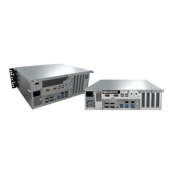
- Page 9 P-cores & E-cores, hybrid core architecture that allocates workload tasks accordingly to boost performance at the edge. This innovative design strikes a balance between high performance and energy efficiency, optimizing the KCO Series to excel in various industrial deployments. KCO-2000-RPL KCO-3000-RPL...
- Page 10 l User’s Manual Chapter 1: Product Introductions KCO-2000/3000-RPL 1.2 Hardware Specification System Processor Support 12/13/14th Gen Intel® ADL & RPL S Processor (LGA 1200, 35W TDP) • Intel® Core i9-14900T/i9-13900TE/i9-12900TE, up to 24 Cores, 36MB Cache, up to 5.5 GHz •...
- Page 11 l User’s Manual Chapter 1: Product Introductions KCO-2000/3000-RPL Expansion 1x PCIe x16 Slot (Gen 5) 1x PCIe x16 Slot (Gen 4, 4-Lane) PCIe 1x PCIe x4 Slot (Gen 4, Open End) 1x PCIe x4 Slot (Gen 3, Open End) Audio 1x Mic-in, 1x Line-in, 1x Line-out 6x USB 3.1 Gen 2 (10 Gbps) 1x USB 3.2 Gen 2x2 (20 Gbps) Type C...
- Page 12 l User’s Manual Chapter 1: Product Introductions KCO-2000/3000-RPL 1.3 System I/O 1.3.1 KCO-2000-RPL USB port COM port Used to connect USB device COM support RS232/422/485 serial DisplayPort LAN port Used to connect a DisplayPort monitor Used to connect the system to a local area network Line-out Used to connect a speaker...
- Page 13 l User’s Manual Chapter 1: Product Introductions KCO-2000/3000-RPL 1.3.2 KCO-3000-RPL USB port COM port Used to connect USB device COM support RS232/422/485 serial DisplayPort LAN port Used to connect a DisplayPort monitor Used to connect the system to a local area network Line-out Used to connect a speaker...
- Page 14 l User’s Manual Chapter 1: Product Introductions KCO-2000/3000-RPL 1.4 Mechanical Dimensions 1.4.1 KCO-2000-RPL Unit: mm...
- Page 15 l User’s Manual Chapter 1: Product Introductions KCO-2000/3000-RPL 1.4.2 KCO-3000-RPL Unit: mm...
- Page 16 Chapter 2 Mechanical Specifications...
- Page 17 l User’s Manual Chapter 2: Mechanical Specifications KCO-2000/3000-RPL Block Diagram...
- Page 18 l User’s Manual Chapter 2: Mechanical Specifications KCO-2000/3000-RPL 2.1 Before you proceed Take note of the following precautions before you install motherboard components or change any motherboard settings. ⚫ Unplug the power cord from the wall socket before touching any component. ⚫...
- Page 19 l User’s Manual Chapter 2: Mechanical Specifications KCO-2000/3000-RPL 2.2.2 Screw Holes Place eight (8) screws into the holes indicated by circles to secure the motherboard to the chassis. Do not over tighten the screws! Doing so can damage the motherboard. Place this side towards the rear of the chassis.
- Page 20 l User’s Manual Chapter 2: Mechanical Specifications KCO-2000/3000-RPL 2.2.3 Motherboard Layout...
- Page 21 l User’s Manual Chapter 2: Mechanical Specifications KCO-2000/3000-RPL 2.2.4 Layout Content List Slots & sockets Label Function Note CPU1 LGA1700 socket DIMMA1~B2 DDR4 Long-DIMM PCIEX16_1 PCIE Gen5 PCIEX4_2 PCIE Gen3 PCIEX4_3 PCIE Gen4 PCIEX16_4 (J) PCIE Gen4 Jumpers Label Function Note JCMOS1 Clear CMOS...
- Page 22 l User’s Manual Chapter 2: Mechanical Specifications KCO-2000/3000-RPL Internal Connector Label Function Note CPU_FAN1 CPU fan connector 4 x 1 wafer, pitch 2.54mm SYS_FAN1 System fan connector 4 x 1 wafer, pitch 2.54mm SYS_FAN2 Chassis fan connector 4 x 1 wafer, pitch 2.54mm F_PANEL1 Intel front panel connector 5 x 2 header, pitch 2.54mm...
- Page 23 l User’s Manual Chapter 2: Mechanical Specifications KCO-2000/3000-RPL 2.3 Central Processing Unit (CPU) The motherboard comes with a surface mount LGA1700 socket designed for the Intel® Core i9/ i7/ i5/ i3 processor in the 1700-land package. ⚫ Your boxed Intel® Core i9/ i7/ i5/ i3 LGA1700 processor package should come with installation instructions for the CPU, fan and heatsink assembly.
- Page 24 l User’s Manual Chapter 2: Mechanical Specifications KCO-2000/3000-RPL 2. Press the load lever with your thumb (A), then move it to the left (B) until it is released from the retention tab. To prevent damage to the socket pins, do not remove the PnP cap unless you are installing a CPU.
- Page 25 l User’s Manual Chapter 2: Mechanical Specifications KCO-2000/3000-RPL 5. Pull back the load lever, then push the load lever (A) until it snaps into the retention tab. The CPU fits in only one correct orientation. DO NOT force the CPU into the socket to prevent bending the connectors on the socket and damaging the CPU! 2.3.2 Installing the CPU Heatsink and Fan...
- Page 26 l User’s Manual Chapter 2: Mechanical Specifications KCO-2000/3000-RPL To install the CPU heatsink and fan: 1. Place the heatsink on top of the installed CPU, making sure that the four fasteners match the holes on the motherboard. Orient the heatsink and fan assembly such that the CPU fan cable is closest to the CPU fan connector.
- Page 27 l User’s Manual Chapter 2: Mechanical Specifications KCO-2000/3000-RPL 3. Connect the CPU fan cable to the connector on the motherboard labeled CPU_FAN1. CPU FAN1 Do not forget to connect the fan cables to the fan connectors. Insufficient air flow inside the system may damage the motherboard components. These are not jumpers! DO NOT place jumper caps on the fan connectors.
- Page 28 l User’s Manual Chapter 2: Mechanical Specifications KCO-2000/3000-RPL 3. Pull up two fasteners at a time in a diagonal sequence to disengage the heatsink and fan assembly 4. Carefully remove the heatsink and fan assembly from the motherboard. 5. Rotate each fastener clockwise to ensure correct orientation when reinstalling.
- Page 29 l User’s Manual Chapter 2: Mechanical Specifications KCO-2000/3000-RPL 2.4 System Memory 2.4.1 Overview The motherboard comes with four 288-pin Double Data Rate 4 (DDR4) Dual Inline Memory Modules (DIMM) sockets. DDR4 SDRAM, an abbreviation for double data rate fourth generation synchronous dynamic random- access memory, is a type of synchronous dynamic random-access memory (SDRAM) with a high bandwidth ("double data rate") interface.
- Page 30 l User’s Manual Chapter 2: Mechanical Specifications KCO-2000/3000-RPL 2.4.2 Installing a DIMM Make sure to unplug the power supply before adding or removing DIMMs or other system components. Failure to do so may cause severe damage to both the motherboard and the components. 1.
- Page 31 l User’s Manual Chapter 2: Mechanical Specifications KCO-2000/3000-RPL 2.5 Expansion Card In the future, you may need to install expansion cards. The following sub-sections describe the slots and the expansion cards that they support. Make sure to unplug the power cord before adding or removing expansion cards.
- Page 32 l User’s Manual Chapter 2: Mechanical Specifications KCO-2000/3000-RPL 2.5.4 PCI Express x4 GEN4 slot This motherboard supports one PCIe x4 slot that complies with the PCIex4 specifications.. 2.5.5 PCI Express x4 GEN 3 slot This motherboard supports two PCIe x4 slot that complies with the PCIe x4 specifications.
- Page 33 l User’s Manual Chapter 2: Mechanical Specifications KCO-2000/3000-RPL 2.5.6 M.2 M Key slot Support PCIe and SATA interface of this connector. 2.5.7 M.2 E key slot Support PCIe and USB interface of this connector.
- Page 34 l User’s Manual Chapter 2: Mechanical Specifications KCO-2000/3000-RPL 2.6 Jumpers 2.6.1 Clear CMOS (JCMOS1) This jumper allows you to clear the Real Time Clock (RTC) RAM in CMOS. You can clear the CMOS memory of date, time, and system setup parameters by erasing the CMOS RTC RAM data. The onboard button cell battery powers the RAM data in CMOS, which includes system setup information such as system passwords.
- Page 35 l User’s Manual Chapter 2: Mechanical Specifications KCO-2000/3000-RPL 2.6.2 AT/ATX Power Mode Select (JPSON1) This jumper allows you to select ATX Mode or AT mode...
- Page 36 l User’s Manual Chapter 2: Mechanical Specifications KCO-2000/3000-RPL 2.7 Connectors 2.7.1 Rear panel connectors Item Name Function Description DP1-4 Display Port The DP port connector USB-C USB 3.2 Gen 2x2 Type-C Connector (Optional) USB 3.2 Gen 2x1 Type-A Connectors This port allows Gigabit connection to a Local Area Network (LAN) through a network hub.
- Page 37 l User’s Manual Chapter 2: Mechanical Specifications KCO-2000/3000-RPL Item Name Function Description USB3-4 USB 3.2 Gen2 Two port USB3.2 Gen2 Connectors Line-in port This port connects a tape, CD, DVD AUDIO1 (Light blue) player, or other audio sources. AUDIO1 Microphone port (Pink) This port connects a microphone.
- Page 38 l User’s Manual Chapter 2: Mechanical Specifications KCO-2000/3000-RPL 2.7.3 System Panel (F_PANEL1) This connector is for a chassis-mounted front panel. The functions are as following. ⚫ ATX Power Button/Soft-off Button (Pin 3-5) This 2-pin connector is for the system power button. Pressing the power button turns the system on or puts the system in sleep or soft-off mode depending on the BIOS settings.
- Page 39 l User’s Manual Chapter 2: Mechanical Specifications KCO-2000/3000-RPL 2.7.4 ATX power connectors (EATXPWR1 & ATX12V1) The connector is for ATX power supply plugs. The power supply plugs are designed to fit these connectors in only one orientation. Find the proper orientation and push down firmly until the connectors completely fit.
- Page 40 l User’s Manual Chapter 2: Mechanical Specifications KCO-2000/3000-RPL 2.7.6 Serial ATA Connector (SATA1~4) 2.7.7 USB Connectors (USB10~13) These connectors are for USB 2.0 ports. Connect the optional USB module cable to any of these connectors, then install the module to a slot opening at the back of the system chassis. These USB connectors comply with USB 2.0 specification that supports up to 480 Mbps connection speed.
- Page 41 l User’s Manual Chapter 2: Mechanical Specifications KCO-2000/3000-RPL 2.7.8 USB3.1 Connector (USB5-6) This connector provides 2 port USB3.1 Gen1 port. Connect the optional USB module cable to any of these connectors, then install the module to a slot opening at the back of the system chassis. These USB connectors comply with USB 3.1 Gen1 specification that supports up to 5Gbps connection speed.
- Page 42 l User’s Manual Chapter 2: Mechanical Specifications KCO-2000/3000-RPL 2.7.10 Front Audio Connector (FP_AUDIO1) This connector is for a chassis-mounted front panel audio I/O module that supports either HD Audio or legacy AC ‘97 (optional) audio standard. 2.7.11 SM Bus Connector (JSMB1) For RD develop use only.
- Page 43 l User’s Manual Chapter 2: Mechanical Specifications KCO-2000/3000-RPL 2.7.12 SPI Connector (SPI1)
- Page 44 Chapter 3 BIOS Setup This chapter tells how to change the system settings through the BIOS Setup menus. Detailed descriptions of the BIOS parameters are also provided.
- Page 45 l User’s Manual Chapter 3: BIOS Setup KCO-2000/3000-RPL 3.1 General Features General Features Item Description Remarks BIOS Sign On **** CT-MRL01 BIOS VX. XX (MM/DD/YYYY) **** BIOS Boot Block function support When BIOS is crash, BIOS can be recovered according This feature is below steps.
- Page 46 l User’s Manual Chapter 3: BIOS Setup KCO-2000/3000-RPL 3.3 BIOS Hotkey Requirements The table below lists the BIOS hotkey requirements. BIOS Hotkey Requirements Hot Key Enter BIOS Setup DEL / ESC 3.4 South Bridge Features POST Error Beep Requirements Item Description Remarks •...
- Page 47 l User’s Manual Chapter 3: BIOS Setup KCO-2000/3000-RPL 3.5 ACPI function Wake-up Devices and Events These devices/events can from this state Remarks wake up the computer… • The LAN adapter monitors network traffic at the Media Independent Interface • Supports LAN wake capabilities with ACPI by Ping or PCIE LAN S3, S4, S5 Magic Packet...
- Page 48 l User’s Manual Chapter 3: BIOS Setup KCO-2000/3000-RPL 3.6 OEM full screen logo BIOS support the following format OEM full screen logo and user can insert it by utility that provided from BIOS vendor. BMP :800x600 24bits, JEPG:800x600 24bits, PCX:800x600 24bits 3.7 SuperIO Feature Support SuperIO Feature Support Item...
- Page 49 l User’s Manual Chapter 3: BIOS Setup KCO-2000/3000-RPL 3.8 Boot Option Boot Option Item Description Remarks The item controls the delay time (in seconds) in the POST Setup Prompt screen until user press DEL / ESC key to enter BIOS setup menu. Timeout The range for the value is from 1 to 65535.
- Page 50 l User’s Manual Chapter 3: BIOS Setup KCO-2000/3000-RPL 3.10 BIOS Setup Menu Title Menu Setup Menu Note Main Advanced Chipset Security Boot Save & Exit Main Menu...
- Page 51 l User’s Manual Chapter 3: BIOS Setup KCO-2000/3000-RPL 3.11 Advanced Menu 3.11.1 CPU Configuration...
- Page 52 l User’s Manual Chapter 3: BIOS Setup KCO-2000/3000-RPL 3.11.2 Power & Performance...
- Page 53 l User’s Manual Chapter 3: BIOS Setup KCO-2000/3000-RPL...
- Page 54 l User’s Manual Chapter 3: BIOS Setup KCO-2000/3000-RPL...
- Page 55 l User’s Manual Chapter 3: BIOS Setup KCO-2000/3000-RPL 3.11.3 PCH-FW Configuration 3.11.4 ACPI Settings...
- Page 56 l User’s Manual Chapter 3: BIOS Setup KCO-2000/3000-RPL 3.11.5 NCT6106D Super IO Configuration...
- Page 57 l User’s Manual Chapter 3: BIOS Setup KCO-2000/3000-RPL...
- Page 58 l User’s Manual Chapter 3: BIOS Setup KCO-2000/3000-RPL 3.11.6 NCT6106D HW Monitor 3.11.7 Trusted Computing...
- Page 59 l User’s Manual Chapter 3: BIOS Setup KCO-2000/3000-RPL 3.11.8 S5 RTC Wake Setting 3.11.9 Serial Port Console Redirection...
- Page 60 l User’s Manual Chapter 3: BIOS Setup KCO-2000/3000-RPL 3.11.10 Intel TXT Information 3.11.11 USB Configuration...
- Page 61 l User’s Manual Chapter 3: BIOS Setup KCO-2000/3000-RPL 3.11.12 Network Stack Configuration 3.11.13 NVME Configuration...
- Page 62 l User’s Manual Chapter 3: BIOS Setup KCO-2000/3000-RPL 3.12 Chipset Menu 3.12.1 System Agent (SA) Configuration...
- Page 63 l User’s Manual Chapter 3: BIOS Setup KCO-2000/3000-RPL...
- Page 64 l User’s Manual Chapter 3: BIOS Setup KCO-2000/3000-RPL...
- Page 65 l User’s Manual Chapter 3: BIOS Setup KCO-2000/3000-RPL 3.12.2 PCH-IO Configuration...
- Page 66 l User’s Manual Chapter 3: BIOS Setup KCO-2000/3000-RPL...
- Page 67 l User’s Manual Chapter 3: BIOS Setup KCO-2000/3000-RPL...
- Page 68 l User’s Manual Chapter 3: BIOS Setup KCO-2000/3000-RPL...
- Page 69 l User’s Manual Chapter 3: BIOS Setup KCO-2000/3000-RPL...
- Page 70 l User’s Manual Chapter 3: BIOS Setup KCO-2000/3000-RPL...
- Page 71 l User’s Manual Chapter 3: BIOS Setup KCO-2000/3000-RPL 3.13 Security Menu 3.13.1 System Agent (SA) Configuration...
- Page 72 l User’s Manual Chapter 3: BIOS Setup KCO-2000/3000-RPL...
- Page 73 l User’s Manual Chapter 3: BIOS Setup KCO-2000/3000-RPL 3.14 Boot...
- Page 74 l User’s Manual Chapter 3: BIOS Setup KCO-2000/3000-RPL 3.15 Save & Exit Menu...
- Page 75 Appendix GPIO & WDT This appendix provides the sample codes of WDT (Watch Dog Timer) and GPIO (General Purpose Input/ Output).
- Page 76 l User’s Manual Appendix – WDT & GPIO KCO-2000/3000-RPL General Purpose Input Output GPI and GPO pins may be implemented as GPIO. Signal Description GPO[0:3] General purpose output pins. Upon a hardware GPI[0:3] General purpose input pins. Pulled high GPIO Configuration Board Design SIO 6126D GPIO Header Buffer...
- Page 77 l User’s Manual Appendix – WDT & GPIO KCO-2000/3000-RPL Q670E GPIO Configuration Buffer Function Type GPP_E13 BOARD_ID0 GPP_E14 BOARD_ID1 GPP_E15 BOARD_ID2 0 : ALC888S (default) 1 : ALC897 GPP_B22 LAN2_DISABLE# I225V Lan Disable : 0 : Disable 1 : Enable (default) GPP_B20 GPP_D16 ATX/AT Mode...
- Page 78 l User’s Manual Appendix – WDT & GPIO KCO-2000/3000-RPL Watchdog Timer Board Design The Watchdog Timer (WDT) is implemented by Nuvoton NCT6126D.. Psuedo Code #include<dos.h> #include<stdio.h> void main(void){ // for 2E int x,pre_rd,rd,status; clrscr(); outportb(0x2E,0x87); outportb(0x2E,0x87); outportb(0x2E,0x30); //CR30 bit1=1 pin77 select WDTO# outportb(0x2F,0x01);...
- Page 79 Copyright © C&T Solution Inc. All Rights Reserved www.candtsolution.com...
Need help?
Do you have a question about the KCO Series and is the answer not in the manual?
Questions and answers