Table of Contents
Advertisement
Quick Links
Advertisement
Table of Contents

Subscribe to Our Youtube Channel
Related Manuals for C&T Solution JCO-3000-ORN-B


Summary of Contents for C&T Solution JCO-3000-ORN-B
- Page 1 JCO-3000-ORN-B (4LAN) Mid-Range AI Edge Computer...
-
Page 2: Table Of Contents
JCO-3000-ORN-B (4LAN) l User’s Manual Table of Contents Prefaces …………………………………………………….……………………………………………. 04 Revision …………………………………………………………………………………………..……………….……….. 04 Disclaimer ………………………………………………………..…….…….………………………….……………….. 04 Copyright Notice …………………………………….…………………….…………………………………………… 04 Trademarks Acknowledgment …………..………………………………………………………....04 Environmental Protection Announcement …………………………….………………….……………….. 04 Safety Precautions ………………………………………….……………………………….…………….………….. 05 Technical Support and Assistance …………………………………….…………….…………….…………….06 Conventions Used in this Manual ………………………………………………………………….….………..06 Package Contents …………………………………………………………………………………………….…………... - Page 3 JCO-3000-ORN-B (4LAN) l User’s Manual 3.2.3 GPIO Control ………………………………………..…..…………………………….……... 35 3.2.4 Device Mode Status ……………………………..…..…………………………….……... 36 3.2.5 Buzzer Control ……………………………..…..…………………………………….……... 36 3.2.6 Power on Buzzer Control ……………..…..…………………………………….……... 37 3.2.7 Com Port Control ………………………..…..…………………………………….……... 37 3.2.8 IGN Power On/Off Delay Time Control …………………………………..……... 38 Case Open Detection (Option) ……………………………………………………………..
-
Page 4: Prefaces
JCO-3000-ORN-B (4LAN) l User’s Manual Prefaces Revision Revision Description Date Manual Released 2024/9/11 Disclaimer All specifications and information in this User’s Manual are believed to be accurate and up to date. C&T Solution Inc. does not guarantee that the contents herein are complete, true, accurate or non-misleading. -
Page 5: Safety Precautions
Preface JCO-3000-ORN-B (4LAN) l User’s Manual Safety Precautions Before installing and using the equipment, please read the following precautions: ⚫ Put this equipment on a reliable surface during installation. Dropping it or letting it fall could cause damage. ⚫ The power outlet shall be installed near the equipment and shall be easily accessible. -
Page 6: Technical Support And Assistance
Preface JCO-3000-ORN-B (4LAN) l User’s Manual Technical Support and Assistance 1. Visit the C&T Solution Inc website at https://www.candtsolution.com where you can find the latest information about the product. 2. Contact your distributor, our technical support team or sales representative for technical support if you need additional assistance. -
Page 7: Package Contents
Before installation, please ensure all the items listed in the following table are included in the package. Item Description : Choosing one • JCO-3000-ORN-B-NX16 Mid-Range AI Industrial Computer • JCO-3000-ORN-B-NX8 Mid-Range AI Industrial Computer • JCO-3000-ORN-B-NN8 Mid-Range AI Industrial Computer • JCO-3000-ORN-B-NN4 Mid-Range AI Industrial Computer • JCO-3000-ORN-B-NX16-4P Mid-Range AI Industrial Computer •... -
Page 8: Optional Accessory
Preface JCO-3000-ORN-B (4LAN) l User’s Manual Optional Accessories Model No. Product Description 1-E09A06008 Adapter AC/DC 12V 5A 60W with 3pin Terminal Block Plug 5.0mm Pitch 1-E09A22102 Adapter AC/DC 24V 9.2A 220W with 3pin Terminal Block Plug 5.0mm Pitch 1-TPCD00005 Power Cord, 3-pin US Type, 180cm... -
Page 9: Chapter 1 Product Introductions
Chapter 1 Product Introductions... -
Page 10: Overview
Chapter 1: Product Introductions JCO-3000-ORN-B (4LAN) l User’s Manual 1.1 Overview The JCO-3000-Series is a fanless industrial-grade computer that is powered by NVIDIA Jetson NX (16GB/8GB) and Nano (8GB/4GB) Orin system-on-module (SOM), engineered for versatile industrial AI applications. This series offers configurations ranging from 40 to 100 TOPS of AI performance, adaptable between 7W and 25W, to ensure efficiency and power in applications like autonomous vehicles, security, robotics, and industrial automation. -
Page 11: Hardware Specification
Chapter 1: Product Introductions JCO-3000-ORN-B (4LAN) l User’s Manual 1.2 Hardware Specification System Processor Support NVIDIA® Jetson Orin NX/Nano GPU with 32 Tensor Cores • 16 GB: 1024-core NVIDIA Ampere architecture GPU (25W/100 TOPS) • 8 GB: 1024-core NVIDIA Ampere architecture GPU (20W/70 TOPS) •... - Page 12 Chapter 1: Product Introductions JCO-3000-ORN-B (4LAN) l User’s Manual Power Optional AC/DC 12V/5A, 60W (Optional) Power Adapter Optional AC/DC 24V/9.2A, 220W (For PoE Model) Power Mode AT, ATX 9~36VDC Power Supply Voltage 12~36VDC (PoE Model) Power Ignition Sensing Adjustable Power Ignition Management...
- Page 13 Chapter 1: Product Introductions JCO-3000-ORN-B (4LAN) l User’s Manual Environment Vibration IEC60068-2-64:2008 With SSD: 5 Grms (5 - 500 Hz, 0.5 hr/axis) Designed to comply with MIL-STD-810G Method 514.7 Procedure I Shock IEC60068-2-27:2008 With SSD: 50G half-sin 11ms Designed to comply with MIL-STD-810G Method 516.7 Procedure I...
-
Page 14: System I/O
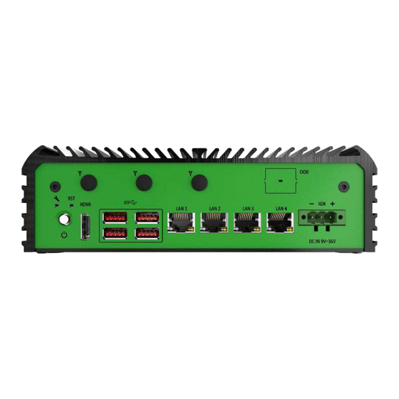
Chapter 1: Product Introductions JCO-3000-ORN-B (4LAN) l User’s Manual 1.3 System I/O JCO-3000-ORN-B (4LAN) Front Panel LAN port HDMI Used to connect the system to a local area Used to connect to HDMI-compatible devices network DC IN 9V~36V Antenna hole... -
Page 15: Rear Panel
Chapter 1: Product Introductions JCO-3000-ORN-B (4LAN) l User’s Manual JCO-3000-ORN-B (4LAN) Rear Panel COM port COM1 ~ COM2 support RS232/422/485 Antenna hole (Switch by MCU) Used to connect an antenna for optional Mini- PCIe WiFi module CAN port Used to connect an ECU (Electronic control unit) -
Page 16: Mechanical Dimension
Chapter 1: Product Introductions JCO-3000-ORN-B (4LAN) l User’s Manual 1.4 Mechanical Dimensions JCO-3000-ORN-B (4LAN) Unit: mm... -
Page 17: Chapter 2 Mechanical Specifications
Chapter 2 Mechanical Specifications... -
Page 18: Switch And Connector Locations
Chapter 2: Mechanical Specifications JCO-3000-ORN-B (4LAN) l User’s Manual 2.1 Switch and Connector Locations 2.1.1 Top View LED2 / 3 / 4 CAN1 COM1 LED_HEAD1 J100 J101 PSE_M1 RESET FORCE_RECOVERY... -
Page 19: Bottom View
Chapter 2: Mechanical Specifications JCO-3000-ORN-B (4LAN) l User’s Manual 2.1.2 Bottom View USB Type-C PWRBTN2 DAUL SIM1 AT_PWR1 CAR_PWR1 COM2 DIO1 MSD1 CON1 M2_KM1 BTB1 M2_KE1 FAN_MCU1 JAUX1 M2_KB1 DC_IN1 RJ45-1 RJ45-2 RJ45-3 RJ45-4 HDMI USB3_1 USB3 PWRBTN1... -
Page 20: Connector / Switch Definition
Chapter 2: Mechanical Specifications JCO-3000-ORN-B (4LAN) l User’s Manual 2.2 Connector / Switch Definition Connector Location Definition AT_ATX AT/ ATX Power Mode Switch PWRBTN1 & PWRBTN2 Power Switch Reset Reset Switch FORCE_RECOVERY1 FORCE_RECOVERY DC_IN1 3-pin DC +9~36V Power Input Connector... -
Page 21: I/O Interface Descriptions
Chapter 2: Mechanical Specifications JCO-3000-ORN-B (4LAN) l User’s Manual 2.3 I/O Interface Descriptions 2.3.1 AT/ ATX Power Mode Switch (BOT) Switch Definition ATX Power Mode (Default) AT Power Mode 2.3.2 CAR_PWR Mode Switch (BOT) Switch Definition CAR mode Mode PC mode Mode (Default) -
Page 22: Dc_In1
Chapter 2: Mechanical Specifications JCO-3000-ORN-B (4LAN) l User’s Manual 2.3.3 DC_IN1 (BOT) Signal +9 ~ 36 2.3.4 CAN Bus (BOT) Signal CAN_L CAN_H... -
Page 23: Com Port
Chapter 2: Mechanical Specifications JCO-3000-ORN-B (4LAN) l User’s Manual 2.3.5 COM Port (TOP/BOT) COM 1 COM 2 Signal Signal ======== Signal Signal ======== ======== ======== ======== ======== RS232/RS422/RS485 Conn” 2*5 =>10Pin Box Header, 2.0mm Pitch DB_9 Port Signal RS422/RS485 Half Duplex Definition... -
Page 24: Fan Conn
Chapter 2: Mechanical Specifications JCO-3000-ORN-B (4LAN) l User’s Manual 2.3.6 FAN Conn” (BOT) Signal TACH 2.3.7 DIO (Digital Input / Output Connector) Signal Signal IN1_1 OUT1_1 IN2_1 OUT2_1 IN3_1 OUT3_1 IN4_1 OUT4_1 IN5_1 OUT5_1 IN6_1 OUT6_1 IN7_1 OUT7_1 IN8_1 OUT8_1... -
Page 25: Mircousb
Chapter 2: Mechanical Specifications JCO-3000-ORN-B (4LAN) l User’s Manual 2.3.8 Mirco USB (Console / Debug Port) Signal VBUS 2.3.9 SIM 1 (BOT) Pin(SIM1/2) Signal Card Detect Switch 2.3.10 BTB1 (BOT) Signal Signal 3Vcc 5Vcc I2C_CLK I2C_DAT... -
Page 26: B Key Socket
Chapter 2: Mechanical Specifications JCO-3000-ORN-B (4LAN) l User’s Manual 2.3.11 M.2 B Key Socket (BOT) Definition Definition CONFIG_3 +3.3V +3.3V FULL_CARD_POWER_OFF# USB_D+ W_DISABLE1# USB_D- WWAN_LED# CONFIG_0 GPIO_11(0/1.8V) P_UIM_VPP PERn1/USB3.0-Rx- USIM1_RST PERp1/USB3.0-Rx+ USIM1_CLK USIM1_DATA PETn1/USB3.0-Tx- USIM1_VDD PETp1/USB3.0-Tx+ PERn0/SATA-B+ PERp0/SATA-B- PETn0/SATA-A- PETp0/SATA-A+... -
Page 27: E Key Socket
Chapter 2: Mechanical Specifications JCO-3000-ORN-B (4LAN) l User’s Manual 2.3.12 M.2 E Key Socket (BOT) Definition Definition +3.3VAUX USB2_D+ +3.3VAUX USB2_D- I2S2_SCLK CNV_WR_1_DN CNV_RF_RESET# CNV_WR_1_DP I2S2_RXD MODEM_CLKREQ CNV_WR_0_DN CNV_WR_0_DP UART_WAKE_L CNV_WR_CLK_DN CNV_BRI_RSP CNV_WR_CLK_DP CNV_RGI_DT CNV_RGI_RSP TxP0 CNV_BRI_DT TxN0 CL_RST# CL_DATA... -
Page 28: M Key Socket
Chapter 2: Mechanical Specifications JCO-3000-ORN-B (4LAN) l User’s Manual 2.3.13 M.2 M Key Socket (BOT) Definition Definition 3.3VAUX 3.3VAUX PER3- PER3+ DAS/DSS- PET3- 3.3VAUX PET3+ 3.3VAUX 3.3VAUX PER2- 3.3VAUX PER2+ PET2- PET2+ PET1- PET1+ DEVSLP SMB_CLK PET0-/SATA_B+ SMB_DATA PER0+/SATA_B+ ALERT-... -
Page 29: Oob_Sw & Uart Oob
Chapter 2: Mechanical Specifications JCO-3000-ORN-B (4LAN) l User’s Manual 2.3.14 OOB_SW & UART OOB Signal Power 5Vcc Power Botton System Reset Power On Off Signal 2.3.15 POE Module Pin A Signal Pin B Signal A1 ~ A11 DC_IN B1~B12 DC_IN... -
Page 30: Chapter 3 Software Setup Guide
Chapter 3 Software Setup Guide... -
Page 31: Os Flash Image Guide
OS image files (file name may vary): $ sudo tar zxvf JCO-3000-ORN-B_JP512_V0.0.1.tar.gz Next, following steps to force the system to start in USB Recovery Mode: Connect the USB type-C cable to the “Flash” port on the JCO-3000-ORN-B and the USB port on the host PC. - Page 32 “0955:7323 Nvidia Corp” Next, following steps to flash BSP image in JCO-3000-ORN-B : Connect the USB type-C cable to the “Flash” port on the JCO-3000-ORN-B and the USB port on the host PC. Enter the following command in terminal to flash the image: $ sudo ./flash-jco-3000.sh...
- Page 33 Chapter 3: Software Setup Guide JCO-3000-ORN-B (4LAN) l User’s Manual The system will reboot after flashing all images.
-
Page 34: Mcu Control Functions
Chapter 3: Software Setup Guide JCO-3000-ORN-B (4LAN) l User’s Manual 3.2 MCU Control Functions 3.2.1 Control Functions MCU driver can control or get status of the below functions. LED Control ◼ GPIO Control ◼ Device Mode Status ◼ ◼ Buzzer Control Com Port Control ◼... -
Page 35: Gpio Control
Chapter 3: Software Setup Guide JCO-3000-ORN-B (4LAN) l User’s Manual 3.2.3 GPIO Control Read or setup GPIO status ⚫ The sysfs path : /sys/bus/i2c/devices/7-0040/ Sysfs files : ⚫ gpio_in (Read-only) : default value 0 ◼ gpio_out (Read/Write) : default value 0 ◼... -
Page 36: Device Mode Status
Chapter 3: Software Setup Guide JCO-3000-ORN-B (4LAN) l User’s Manual 3.2.4 Device Mode Status Read device mode as PC MODE or IGN MODE The sysfs path : /sys/bus/i2c/devices/7-0040/ ⚫ ⚫ Sysfs files : device_mode (Read-only) ⚫ Control method : $ cat /sys/bus/i2c/devices/7-0040/device_mode... -
Page 37: Power On Buzzer Control
Chapter 3: Software Setup Guide JCO-3000-ORN-B (4LAN) l User’s Manual 3.2.6 Power on Buzzer Control Enable or disable the buzzer when power on The sysfs path : /sys/bus/i2c/devices/7-0040/ ⚫ Sysfs files : power_on_buzzer (Read/Write) : default value 1 (EEPROM Save) ⚫... -
Page 38: Ign Power On/Off Delay Time Control
Chapter 3: Software Setup Guide JCO-3000-ORN-B (4LAN) l User’s Manual 3.2.8 IGN Power On/Off Delay Time Control Set IGN ON/OFF to SB-PW ON/OFF delay time at ignition mode The sysfs path : /sys/bus/i2c/devices/7-0040/ ⚫ ⚫ Sysfs files : ign_on_dly_s (Read/Write) : default value 10 (EEPROM Save) ■... - Page 39 Chapter 3: Software Setup Guide JCO-3000-ORN-B (4LAN) l User’s Manual...
-
Page 40: Case Open Detection (Option)
Chapter 3: Software Setup Guide JCO-3000-ORN-B (4LAN) l User’s Manual 3.3 Case Open Detection (Option) 3.3.1 Driver Function OCR (Open Case Recorder) driver can record case open time in log when system boot. However, can also check the case status by OCR function control at a specific time. -
Page 41: Ocr Function Control
Chapter 3: Software Setup Guide JCO-3000-ORN-B (4LAN) l User’s Manual 3.3.3 OCR function control ⚫ Get or Set the OCR time ◼ The sysfs path : /sys/bus/i2c/devices/7-0051/ Sysfs files : time_now (Read/Write) ◼ Control method : ◼ ◆ Get OCR time $ cat /sys/bus/i2c/devices/7-0051/time_now ◆... - Page 42 Chapter 3: Software Setup Guide JCO-3000-ORN-B (4LAN) l User’s Manual Enable open case recorder function ⚫ The sysfs path : /sys/bus/i2c/devices/7-0051/ ◼ Sysfs files : enable_tsr (Read/Write) ◼ Control method : ◼ Enable function: $ echo 1 > /sys/bus/i2c/devices/7-0051/enable_tsr Disable function: $ echo 0 >...
- Page 43 Copyright © C&T Solution Inc. All Rights Reserved www.candtsolution.com...
Need help?
Do you have a question about the JCO-3000-ORN-B and is the answer not in the manual?
Questions and answers