Table of Contents
Advertisement
Quick Links
Advertisement
Table of Contents

Related Manuals for C&T Solution VCO-6000-ADL


Summary of Contents for C&T Solution VCO-6000-ADL
- Page 1 VCO-6000-ADL Machine Vision Computer...
-
Page 2: Table Of Contents
VCO-6000-ADL l User’s Manual Table of Contents Prefaces …………………………………………………….……………………………………………. 04 Revision …………………………………………………………………………………………..……………….……….. 04 Disclaimer ………………………………………………………..…….…….………………………….……………….. 04 Copyright Notice …………………………………….…………………….…………………………………………… 04 Trademarks Acknowledgment …………..………………………………………………………....04 Environmental Protection Announcement …………………………….………………….……………….. 04 Safety Precautions ………………………………………….……………………………….…………….………….. 05 Technical Support and Assistance …………………………………….…………….…………….…………….06 Conventions Used in this Manual ………………………………………………………………….….………..06 Package Contents …………………………………………………………………………………………….…………... - Page 3 VCO-6000-ADL l User’s Manual 3.3.10. Power IGN Mode ……………………..…………………….…....….…… 92 3.3.11 Wake system from S5 ……..……….………………......……….. 93 3.3.12 Serial Port Console Redirection ……………..….......…………. 94 3.3.13 USB Configuration ……………..……………………………………....…….. 95 3.3.14 Network Stack Configuration .……………………………………....…….. 96 3.3.15 CSM Configuration .……………………………………………..……....…….. 97 3.3.16 NVMe Configuration .…………………………………………..……....……..
-
Page 4: Prefaces
VCO-6000-ADL l User’s Manual Prefaces Revision Revision Description Date Manual Released 2023/06/30 Disclaimer All specifications and information in this User’s Manual are believed to be accurate and up to date. C&T Solution Inc. does not guarantee that the contents herein are complete, true, accurate or non-misleading. -
Page 5: Safety Precautions
Preface VCO-6000-ADL l User’s Manual Safety Precautions Before installing and using the equipment, please read the following precautions: ⚫ Put this equipment on a reliable surface during installation. Dropping it or letting it fall could cause damage. ⚫ The power outlet shall be installed near the equipment and shall be easily accessible. -
Page 6: Technical Support And Assistance
Preface VCO-6000-ADL l User’s Manual Technical Support and Assistance 1. Visit the C&T Solution Inc website at https://www.candtsolution.com where you can find the latest information about the product. 2. Contact your distributor, our technical support team or sales representative for technical support if you need additional assistance. -
Page 7: Package Contents
Preface VCO-6000-ADL l User’s Manual Package Contents Before installation, please ensure all the items listed in the following table are included in the package. Item Description Q’ty : Choosing one • VCO-6000-ADL-3E Series • VCO-6000-ADL-4E Series Wall Mount Kit Accessory Kit... -
Page 8: Ordering Information
Preface VCO-6000-ADL l User’s Manual Ordering Information VCO-6000-ADL-3E Series Model No. Product Description Machine Vision Computer w/ LGA 1700 for Intel 12/13 Gen CPU VCO-6000-ADL-3E & R680E PCH, 3x PCIe Machine Vision Computer w/ LGA 1700 for Intel 12/13 Gen CPU VCO-6000-ADL-3E-4B7M &... -
Page 9: Optional Accessory
Preface VCO-6000-ADL l User’s Manual Optional Accessories Model No. Product Description 1-E09A22102 Adapter AC/DC 24V 9.2A 220W with 3pin Terminal Block Plug 5.0mm Pitch 1-E09A22801 Adapter AC/DC 24V/11.67A 280W with 3pin Terminal Block Plug 5.0mm Pitch 1-E09A36001 Adapter AC/DC 24V/15A 360W with 3pin Terminal Block Plug 5.0mm Pitch... -
Page 10: Chapter 1 Product Introductions
Chapter 1 Product Introductions... -
Page 11: Overview
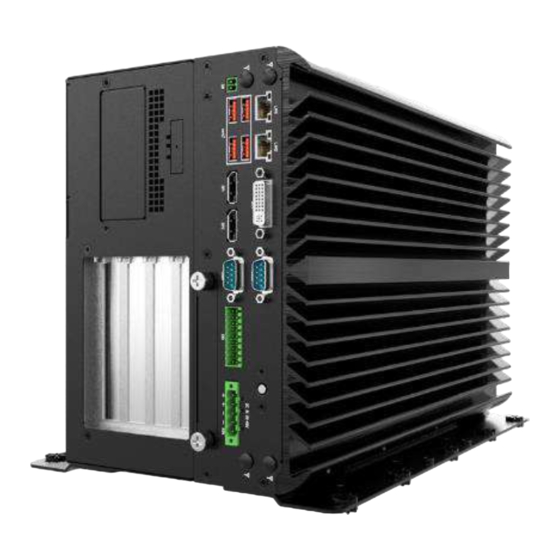
Chapter 1: Product Introductions 1.1 Overview The VCO-6000-ADL Series Machine Vision Systems provide powerful computing and excellent graphic performance, which are suitable for graphic-intensive and computing-oriented applications including image and vision measurement, machine automation. Delivering high quality, durability and compact... - Page 12 VCO-6000-ADL l User’s Manual Chapter 1: Product Introductions VCO-6000-ADL-3E Series Model No. Front Panel • VCO-6000-ADL-3E 1x PCIe x16 (Gen4), 2x PCIe x1 (Gen3) • VCO-6000-ADL-3E-2PWR 1x PCIe x16 (Gen4), 2x PCIe x1 (Gen3), 2x Power input • VCO-6000-ADL-3E-4B7M 1x PCIe x16 (Gen4), 2x PCIe x1 (Gen3), 6x HDD •...
- Page 13 VCO-6000-ADL l User’s Manual Chapter 1: Product Introductions VCO-6000-ADL-4E Series Model No. Front Panel • VCO-6000-ADL-4E 2x PCIe x16 Slot (x8 Lane, Gen 4), 1x PCIe x4 (x1 Lane, Gen 3) • VCO-6000-ADL-4E-2PWR 2x PCIe x16 Slot (x8 Lane, Gen 4),...
-
Page 14: Key Feature
VCO-6000-ADL l User’s Manual Chapter 1: Product Introductions 1.1.1 Key Features ⚫ LGA 1700 socket for 12/13th Gen. Intel® ADL-S & RPL-S Processor (65W/35W TDP) ⚫ Intel® R680E chipset ⚫ 2x DDR5 4800/5600MHz SODIMM. Max. up to 64GB ⚫ Triple Independent Display by 1x DVI-I and 2x DisplayPort ⚫... -
Page 15: Hardware Specification
VCO-6000-ADL l User’s Manual Chapter 1: Product Introductions 1.2 Hardware Specification System Processor Support 12/13 Gen Intel® ADL-S & RPL-S Processor (LGA 1700, 65W/35W TDP) • Intel® Core™ i9-13900TE/i9-12900TE, up to 24 Cores, 36MB Cache, up to 5 GHz, 35W •... - Page 16 VCO-6000-ADL l User’s Manual Chapter 1: Product Introductions Storage SIM Socket VCO-6000-ADL-3E-4B7M 1x Internal 2.5" SATA/SSD HDD Bay (support VCO-6000-ADL-3E-4B7M-2PWR H=9mm) VCO-6000-ADL-4E-4B7M 5x Removable 2.5“ SATA HDD Bay (support H=7mm, Hot-swappable) VCO-6000-ADL-4E-4B7M-2PWR 1x Internal 2.5" SATA/SSD HDD Bay (support 1x M.2 B Key,...
- Page 17 VCO-6000-ADL l User’s Manual Chapter 1: Product Introductions Operating System Windows Windows 10/11 Linux Linux kernel Power Optional AC/DC 24V/9.2A, 220W Power Adapter Optional AC/DC 24V/11.67A, 280W (GPU/Card Expansion) Optional AC/DC 24V/15A, 360W (i7/i9 CPU/GPU/Card Expansion) Power Mode AT, ATX...
-
Page 18: System I/O
VCO-6000-ADL l User’s Manual Chapter 1: Product Introductions 1.3 System I/O 1.3.1 VCO-6000-ADL-3E ATX power on/off switch DisplayPort Press to power-on or power-off the system Used to connect a DisplayPort monitor DC IN LAN Port Used to plug a DC power input with terminal... -
Page 19: Vco-6000-Adl-3E Expansion
VCO-6000-ADL l User’s Manual Chapter 1: Product Introductions VCO-6000-ADL-3E Series Expansion VCO-6000-ADL-3E / VCO-6000-ADL-3E-4B7M / VCO-6000-ADL-3E-2B15M / VCO-6000-ADL-3E-2N15M / VCO-6000-ADL-3E-2PWR / VCO-6000-ADL-3E-4B7M-2PWR / VCO-6000-ADL-3E-2B15M-2PWR / VCO-6000-ADL-3E-2N15M-2PWR Storage (optional) DC IN 12 ~ 48VDC (optional) • 4B7M: • 12 ~ 48VDC (For GPU/Card Expansion) 4x Removable 2.5"... -
Page 20: Vco-6000-Adl-4E
VCO-6000-ADL l User’s Manual Chapter 1: Product Introductions 1.3.2 VCO-6000-ADL-4E ATX power on/off switch DisplayPort Press to power-on or power-off the system Used to connect a DisplayPort monitor DC IN LAN Port Used to plug a DC power input with terminal... -
Page 21: Vco-6000-Adl-4E Expansion
VCO-6000-ADL l User’s Manual Chapter 1: Product Introductions VCO-6000-ADL-4E Series Expansion VCO-6000-ADL-4E / VCO-6000-ADL-4E-4B7M / VCO-6000-ADL-4E-2B15M / VCO-6000-ADL-4E-2N15M / VCO-6000-ADL-4E-2PWR / VCO-6000-ADL-4E-4B7M-2PWR / VCO-6000-ADL-4E-2B15M-2PWR / VCO-6000-ADL-4E-2N15M-2PWR Storage (optional) DC IN 12 ~ 48VDC (optional) • 4B7M: • 12 ~ 48VDC (For GPU/Card Expansion) 4x Removable 2.5"... -
Page 22: Mechanical Dimension
VCO-6000-ADL l User’s Manual Chapter 1: Product Introductions 1.4 Mechanical Dimensions 1.4.1 VCO-6000-ADL-3E Series Unit: mm VCO-6000-ADL-3E / VCO-6000-ADL-3E-4B7M / VCO-6000-ADL-3E-2B15M / VCO-6000-ADL-3E-2N15M / VCO-6000-ADL-3E-2PWR / VCO-6000-ADL-3E-4B7M-2PWR / VCO-6000-ADL-3E-2B15M-2PWR / VCO-6000-ADL-3E-2N15M-2PWR... -
Page 23: Vco-6000-Adl-4E
VCO-6000-ADL l User’s Manual Chapter 1: Product Introductions 1.4.2 VCO-6000-ADL-4E Series Unit: mm VCO-6000-ADL-4E / VCO-6000-ADL-4E-4B7M / VCO-6000-ADL-4E-2B15M / VCO-6000-ADL-4E-2N15M / VCO-6000-ADL-4E-2PWR / VCO-6000-ADL-4E-4B7M-2PWR / VCO-6000-ADL-4E-2B15M-2PWR / VCO-6000-ADL-4E-2N15M-2PWR... -
Page 24: Chapter 2 Mechanical Specifications
Chapter 2 Mechanical Specifications... -
Page 25: Switch And Connector Locations
VCO-6000-ADL l User’s Manual Chapter 2: Mechanical Specifications 2.1 Switch and Connector Locations 2.1.1 Top View DP 2 DP 1 PWR_SW 2 COM 1_2 DVI_I 1 CN 4 CN 3 ACC 1 DC_IN 1 DIO 1 DC_IN 2 SODIMM 1... -
Page 26: Bottom View
VCO-6000-ADL l User’s Manual Chapter 2: Mechanical Specifications 2.1.2 Bottom View PCIE 2 SODIMM 2 PCIE 1 SATA 2 SATA 3 SATA 1 SL 1 RESET SIM 2... -
Page 27: Connector / Switch Definition
VCO-6000-ADL l User’s Manual Chapter 2: Mechanical Specifications 2.2 Connector / Switch Definition Connector Location Definition AT_ATX AT / ATX Power Mode Switch PWR_SW1,2,3 Power Switch RESET Reset Switch DC_IN1 5-pin DC +9~48V Power Input Connector DC_IN2 6-pin DC +9~48V Power Input Connector... -
Page 28: I/O Interface Descriptions
VCO-6000-ADL l User’s Manual Chapter 2: Mechanical Specifications 2.3 I/O Interface Descriptions 2.3.1 ESPI Debug Con JESPI 1 Signal Signal ESPI_IO_0 3.3V ESPI_IO_1 ESPI_RESET# ESPI_IO_2 ESPI_CS# ESPI_IO_3 ESPI_CLOCK 2.3.2 Power Con POWER 1~4 Signal +12V... - Page 29 VCO-6000-ADL l User’s Manual Chapter 2: Mechanical Specifications 2.3.3 DC IN 1 : 9V ~ 48V DC IN 1 Signal +9V ~ +48V +9V ~ +48V 2.3.4 DC IN 2 : 9V ~ 48V DC IN 2 Signal +9V ~ +48V...
- Page 30 VCO-6000-ADL l User’s Manual Chapter 2: Mechanical Specifications 2.3.5 COM Con COM 5, COM 6 Signal Signal DCD# DSR# RTS# CTS# DTR# RS232 / RS422 / RS485 Connector 2x5 10-pin box header, 2.0mm pitch RS422 / 485 Full Duplex Signal...
- Page 31 VCO-6000-ADL l User’s Manual Chapter 2: Mechanical Specifications COM Con COM 3 , COM 4 Signal Signal DCD# DSR# RTS# CTS# DTR#...
- Page 32 VCO-6000-ADL l User’s Manual Chapter 2: Mechanical Specifications COM Con COM 1_2 RS232 / RS422 / RS485 Connector Type: 9-pin D-Sub RS422 / 485 Full Duplex RS232 Definition RS485 Half Duplex Definition Definition DCD# DATA- DATA+ DTR# DSR# RTS# CTS#...
- Page 33 VCO-6000-ADL l User’s Manual Chapter 2: Mechanical Specifications 2.3.6 SF100 SPI Con JP 1 Switch Definition Power ( 3V ) MISO MOSI SPI_GATE#...
- Page 34 VCO-6000-ADL l User’s Manual Chapter 2: Mechanical Specifications 2.3.7 AT / ATX Power Mode Switch AT_ATX Switch Definition 1-2 (Left) ATX Power Mode (Default) 2-3 (Right) AT Power Mode 2.3.8 PC / Car Mode Switch CAR_PWR Switch Definition 1-2 (Left)
- Page 35 VCO-6000-ADL l User’s Manual Chapter 2: Mechanical Specifications 2.3.9 Line-out Jack (Green) Connector Type: 5-pin Phone Jack LINE_OUT Switch Definition OUT_R OUT_L 2.3.10 Microphone-in Jack (Pink) Connector Type: 5-pin Phone Jack MIC_IN Switch Definition MIC_R MIC_L...
- Page 36 VCO-6000-ADL l User’s Manual Chapter 2: Mechanical Specifications 2.3.11 Clear BIOS Switch CLR_CMOS Switch Definition 1-2 (Left) Normal Status (Default) 2-3 (Right) Clear BIOS 2.3.12 Power Button PWR_SW 1 Switch Definition Power Button...
- Page 37 VCO-6000-ADL l User’s Manual Chapter 2: Mechanical Specifications 2.3.13 Remote Power Switch Type: Terminal Block 1x2 2-pin, 3.5mm pitch PWR_SW 2 Definition Power Button 2.3.14 For WCO-6000-ADL PWR_SW 3 Definition Power Button PWR_LED HDD_LED...
- Page 38 VCO-6000-ADL l User’s Manual Chapter 2: Mechanical Specifications 2.3.15 Reset Button RESET Switch Definition RESET 2.3.16 USB 3.1 Connector, GEN2 x4 ports, Type A USB 3_1 , USB 3_2 , USB 3_3 , USB 3_4 Definition USB2_D- USB2_D+ USB3_RX- USB3_RX+...
- Page 39 VCO-6000-ADL l User’s Manual Chapter 2: Mechanical Specifications 2.3.17 USB3.0 Connector, 2x5 10-pin header, 2.0mm pitch CN 1 Switch Definition USB3_TX- USB_D- USB3_TX+ USB_D+ USB3_RX- USB3_RX+...
- Page 40 VCO-6000-ADL l User’s Manual Chapter 2: Mechanical Specifications 2.3.18 USB2.0 Connector, 2x5 10-pin box header, 2.0mm pitch USB 2_L Switch Definition USB2_D- USB2_D+...
- Page 41 VCO-6000-ADL l User’s Manual Chapter 2: Mechanical Specifications 2.3.19 LAN and USB 3.1 GEN 2 Ports Connector Type: RJ45 port with LEDs and dual USB 3.1 ports CN3, CN4 Definition Definition Definition LAN1_MDI0P USB2_D1- USB2_D2- LAN1_MDI0N USB2_D1+ USB2_D2+ LAN1_MDI1P LAN1_MDI2P...
- Page 42 VCO-6000-ADL l User’s Manual Chapter 2: Mechanical Specifications 2.3.20 DVI-I Connector DVI_I 1 Definition Definition DVI_TX2- DVI Hot Plug Detect DVI_TX2+ DVI_TX0- DVI_TX0+ VGA_DDC_CLOCK DVI_DDC_CLOCK VGA_DDC_DATA DVI_DDC_DATA VGA VSYNC DVI_TXCLK+ DVI_TX1- DVI_TXCLK- DVI_TX1+ VGA_RED VGA_GREEN VGA_BLUE VGA_HSYNC...
- Page 43 VCO-6000-ADL l User’s Manual Chapter 2: Mechanical Specifications 2.3.21 Display Port Connector DP 1, DP 2 Definition Definition DP_LANE0_P DP_LANE3_N DP_LANE0_N DP_LANE1_P DP_AUX_P DP_LANE1_N DP_LANE2_P DP_AUX_N DP_HPD DP_LANE2_N DP_LANE3_P +3.3V...
- Page 44 VCO-6000-ADL l User’s Manual Chapter 2: Mechanical Specifications 2.3.22 Digital Input / Output Connector Type: Terminal Block 2x9 18-pin, 3.5mm pitch Definition Definition DIN1 DOUT1 DIN2 DOUT2 DIN3 DOUT3 DIN4 DOUT4 DIN5 DOUT5 DIN6 DOUT6 DIN7 DOUT7 DIN8 DOUT8 DC power input (+5V~+24V)
- Page 45 VCO-6000-ADL l User’s Manual Chapter 2: Mechanical Specifications CAN1 CAN2 Signal CAN_H CAN_L FAN_SIO Switch Definition +12V Sense Control...
- Page 46 VCO-6000-ADL l User’s Manual Chapter 2: Mechanical Specifications FAN_MCU Signal +12V Sense Control For FAN_MCU RT TEMP1...
- Page 47 VCO-6000-ADL l User’s Manual Chapter 2: Mechanical Specifications BH 1 Signal +3.3V PLTRST# SLP S4 SLP S5 RSTBTN# Switch Definition I2C_DATA I2C_CLK...
- Page 48 VCO-6000-ADL l User’s Manual Chapter 2: Mechanical Specifications Signal SMB_DATA SMB_CLK...
- Page 49 VCO-6000-ADL l User’s Manual Chapter 2: Mechanical Specifications 2.3.23 LED Status Act LED Status Definition Blinking Yellow Data Activity No Activity Link LED Status CN3 Definition Steady Orange 1 Gbps Network Link Steady Green 100 Mbps Network Link 10 Mbps Network Link...
- Page 50 VCO-6000-ADL l User’s Manual Chapter 2: Mechanical Specifications LED Status WDT_LED : WDTOUT LED Status Definition WDTOUT LED+ WDTOUT LED-...
- Page 51 VCO-6000-ADL l User’s Manual Chapter 2: Mechanical Specifications 2.3.24 Top size SIM Card Socket SIM1 SIM1 (Top size for M.2 B Key) Definition Definition UIM_PWR UIM_VPP UIM_RESET UIM_DATA UIM_CLK...
- Page 52 VCO-6000-ADL l User’s Manual Chapter 2: Mechanical Specifications 2.3.25 Bottom size SIM Card Socket SIM2 SIM2 (Bottom size for Mini PCIe) Definition Definition UIM_PWR UIM_VPP UIM_RESET UIM_DATA UIM_CLK...
- Page 53 VCO-6000-ADL l User’s Manual Chapter 2: Mechanical Specifications 2.3.26 Mini PCI-Express / mSATA Socket MINIPCIE Definition Definition WAKE# +3.3V +1.5V CLKREQ# UIM_PWR UIM_DATA REFCLK- UIM_CLK REFCLK+ UIM_RST UIM_VPP RESET# +3.3VAUX +1.5V...
- Page 54 VCO-6000-ADL l User’s Manual Chapter 2: Mechanical Specifications Definition Definition SMB_CLK SMB_DATA USB2_D- USB2_D+ +3.3V +3.3V DEVSLP +1.5V PCIE_MSATA_SEL +3.3V...
- Page 55 VCO-6000-ADL l User’s Manual Chapter 2: Mechanical Specifications 2.3.27 M.2 E Key Socket M2_KE Definition Definition +3.3VAUX USB2_D+ +3.3VAUX USB2_D- I2S2_SCLK CNV_WR_1_DN CNV_RF_RESET# CNV_WR_1_DP I2S2_RXD MODEM_CLKREQ CNV_WR_0_DN CNV_WR_0_DP UART_WAKE_L CNV_WR_CLK_DN CNV_BRI_RSP CNV_WR_CLK_DP CNV_RGI_DT CNV_RGI_RSP TxP0 CNV_BRI_DT...
- Page 56 VCO-6000-ADL l User’s Manual Chapter 2: Mechanical Specifications Definition Definition TxN0 CL_RST# CL_DATA RxP0 CL_CLK RxN0 CNV_PA_BLANKING CNV_MFUART2_TXD REFCLK0+ CNV_MFUART2_RXD REFCLK0- SUSCLK PERST0# M2_KEY-E_BT_DIS2# WAKE0# M2_KEY-E_WIFI_DIS1# SMBDATAS_DUAL CNV_WT_1_DN SMBCLKS_DUAL CNV_WT_1_DP SMBALERT# Pull Low CNV_WT_0_DN PERST1# CNV_WT_0_DP WAKE1# CNV_WT_CLK_DN +3.3VAUX CNV_WT_CLK_DP...
- Page 57 VCO-6000-ADL l User’s Manual Chapter 2: Mechanical Specifications 2.3.28 M.2 B Key Socket M2_KB Definition Definition CONFIG_3 +3.3V +3.3V FULL_CARD_POWER_OFF# USB_D+ W_DISABLE1# USB_D- WWAN_LED# CONFIG_0 GPIO_11(0/1.8V) P_UIM_VPP PERn1/USB3.0-Rx- USIM1_RST PERp1/USB3.0-Rx+ USIM1_CLK USIM1_DATA PETn1/USB3.0-Tx- USIM1_VDD...
- Page 58 VCO-6000-ADL l User’s Manual Chapter 2: Mechanical Specifications Definition Definition PETp1/USB3.0-Tx+ PERn0/SATA-B+ PERp0/SATA-B- PETn0/SATA-A- PETp0/SATA-A+ PCIE_RST_N PCIE_CLKREQ_N PCIE_REFCLK_M PCIE_WAKE_N PCIE_REFCLK_P USIM1_DET SUSCLK(32kHz) CONFIG_1 +3.3VAUX +3.3VAUX +3.3VAUX CONFIG_2...
- Page 59 VCO-6000-ADL l User’s Manual Chapter 2: Mechanical Specifications 2.3.29 PCI-Express x1 Slot PCIE 2 Definition Definition +12V FAN_P4 +12V +12V +12V +12V SMB_CLK SMB_DATA +3.3V +3.3V +3.3VAUX +3.3V WAKE# RESET# FAN_P3 REFCLK+ TxP0 REFCLK- TxN0 RxP0 FAN_PER RxN0...
- Page 60 VCO-6000-ADL l User’s Manual Chapter 2: Mechanical Specifications 2.3.30 PCI-Express x16 Slot PCIE 1 Definition Definition +12V +12V +12V +12V +12V SMB_CLK SMB_DATA +3.3V +3.3V +3.3VAUX +3.3V WAKE# RESET# REFCLK+...
- Page 61 VCO-6000-ADL l User’s Manual Chapter 2: Mechanical Specifications Definition Definition TxP0 REFCLK- TxN0 RxP0 RxN0 TxP1 TxN1 RxP1 RxN1 TxP2 TxN2 RxP2 RxN2 TxP3 TxN3 RxP3 RxN3 CFG_5 TxP4 CFG_6 TxN4 RxP4 RxN4 TxP5 TxN5...
- Page 62 VCO-6000-ADL l User’s Manual Chapter 2: Mechanical Specifications Definition Definition RxP5 RxN5 TxP6 TxN6 RxP6 RxN6 TxP7 TxN7 RxP7 RxN7 TxP8 TxN8 RxP8 RxN8 TxP9 TxN9 RxP9 RxN9 TxP10 TxN10 RxP10 RxN10 TxP11 TxN11...
- Page 63 VCO-6000-ADL l User’s Manual Chapter 2: Mechanical Specifications Definition Definition RxP11 RxN11 TxP12 TxN12 RxP12 RxN12 TxP13 TxN13 RxP13 RxN13 TxP14 TxN14 RxP14 RxN14 TxP15 TxN15 RxP15 RxN15...
- Page 64 VCO-6000-ADL l User’s Manual Chapter 2: Mechanical Specifications 2.3.31 PCI-Express x8 Slot PCIE (LAN_L , LAN_R) Definition Definition +12V +12V +12V +12V +12V SMB_CLK SMB_DATA +3.3V +3.3V +3.3VAUX +3.3V WAKE# RESET# REFCLK+ TxP0 REFCLK- TxN0...
- Page 65 VCO-6000-ADL l User’s Manual Chapter 2: Mechanical Specifications Definition Definition RxP0 RxN0 TxP1 TxN1 RxP1 RxN1 TxP2 TxN2 RxP2 RxN2 TxP3 TxN3 RxP3 RxN3 9_48VSB_IN 9_48VSB_IN 9_48VSB_IN 9_48VSB_IN 9_48VSB_IN 9_48VSB_IN 9_48VSB_IN 9_48VSB_IN 9_48VSB_IN 9_48VSB_IN 9_48VSB_IN 9_48VSB_IN 9_48VSB_IN 9_48VSB_IN 9_48VSB_IN 9_48VSB_IN...
- Page 66 VCO-6000-ADL l User’s Manual Chapter 2: Mechanical Specifications 2.3.32 SATA with Power Connector SATA 1, SATA 2 Definition Definition +12V DEVSLP +12V +12V...
- Page 67 VCO-6000-ADL l User’s Manual Chapter 2: Mechanical Specifications SATA 3 Definition Definition Definition Definition RxP1 RxP0 TxP1 TxP0 RxN1 RxN0 TxN1 TxN0 RxP3 RxP2 TxP3 TxP2 RxN3 RxN2 TxN3 TxN2...
- Page 68 VCO-6000-ADL l User’s Manual Chapter 2: Mechanical Specifications SL 1 Slimline PCIe x8 Definition Definition TxP0 RxP0 TxN0 RxN0 TxP1 RxP1 TxN1 RxN1 RST#1 CLKP1 RST#2 CLKN1 RST#3 CLKP2 RST#4 CLKN2 TxP2 RxP2 TxN2 RxN2...
- Page 69 VCO-6000-ADL l User’s Manual Chapter 2: Mechanical Specifications Definition Definition TxP3 RxP3 TxN3 RxN3 TxP4 RxP4 TxN4 RxN4 TxP5 RxP5 TxN5 RxN5 PRSNT#1 CLKP3 PRSNT#2 CLKN3 RST#3 CLKP4 PRSNT#4 CLKN4 TxP6 RxP6 TxN6 RxN6 TxP7 RxP7 TxN7 RxN7...
-
Page 70: Chapter 3 Bios Setup
Chapter 3 BIOS Setup... -
Page 71: Bios Introduction
VCO-6000-ADL l User’s Manual Chapter 3: BIOS Setup 3.1 BIOS Introduction The BIOS provides an interface to modify the configuration. When the battery is removed, all the parameters will be reset. BIOS Setup Power on the embedded system and by pressing <Del> immediately allows you to enter the setup screens. -
Page 72: Main Setup
VCO-6000-ADL l User’s Manual Chapter 3: BIOS Setup 3.2 Main Setup Press <Del> to enter BIOS CMOS Setup Utility. The Main setup screen is showed as following when the setup utility is entered. System Date/Time is set up in the Main Menu. -
Page 73: Advanced Setup
VCO-6000-ADL l User’s Manual Chapter 3: BIOS Setup 3.3 Advanced Setup... -
Page 74: Connectivity Configuration
VCO-6000-ADL l User’s Manual Chapter 3: BIOS Setup 3.3.1 Connectivity Configuration Item Options Description CNVi Mode Disable Integrated, This option configures Connectivity. [Auto Auto Detection[Default] Detection] means that if Discrete solution is discovered it will be enabled by default. Otherwise Integrated solution (CNVi) will be enabled;... -
Page 75: Cpu Configuration
VCO-6000-ADL l User’s Manual Chapter 3: BIOS Setup 3.3.2 CPU Configuration Item Options Description Intel (VMX) Virtualization Disabled, When enabled, a VMM can utilize the Technology Enabled[Default] additional hardware capabilities provided by Virtualization Technology. Active Performance-cores All[Default] , Number of P-cores to enable in each processor 5,4,3, package. - Page 76 VCO-6000-ADL l User’s Manual Chapter 3: BIOS Setup 3.3.2.1 Efficient-core Information 3.3.2.2 Performance-core Information...
-
Page 77: Pch-Fw Configuration
VCO-6000-ADL l User’s Manual Chapter 3: BIOS Setup 3.3.3 PCH-FW Configuration Item Options Description AMT BIOS Features Disabled, When disabled AMT BIOS Features are no longer Enabled[Default] supported and user is no longer able to access MEBx Setup. Note:This option does not disable Manageability Features in FW. -
Page 78: Sata And Rst Configuration
VCO-6000-ADL l User’s Manual Chapter 3: BIOS Setup 3.3.4 SATA and RST Configuration Item Options Description SATA Controller(s) Enabled[Default] Enable/Disable SATA Device. Disabled SATA Port Disabled, Enable/Disable SATA Port. Enabled[Default] Hot Plug Disabled, Designates this port as Hot Pluggable. Enabled[Default]... -
Page 79: Rst (Uefi Raid) Configuration
VCO-6000-ADL l User’s Manual Chapter 3: BIOS Setup 3.3.5 RST (UEFI RAID) Configuration How to set the UEFI RAID: 1. When set to “Enable VMD controller“, please save change reset system. 2. After reboot the system, please into BIOS utility and then will see “Intel (R) Rapid Storage... - Page 80 VCO-6000-ADL l User’s Manual Chapter 3: BIOS Setup 3. Into Intel(R) Rapid Storage Technology, and start create RAID volume. 4. Start Create the RAID ■ Select Disk that you want to do the RAID ■ Select [x]; No-Select [ ]...
-
Page 81: Trusted Computing
VCO-6000-ADL l User’s Manual Chapter 3: BIOS Setup 3.3.6 Trusted Computing Item Options Description Security Device Support Enabled, Enable/Disable BIOS support for security Disabled[Default] , device. O.S. will not show Security Device.TCG EFI protocol and INT1A interface will not be available. -
Page 82: Acpi Settings
VCO-6000-ADL l User’s Manual Chapter 3: BIOS Setup 3.3.7 ACPI Settings Item Options Description Enable Hibernation Disabled , Enables or Disables System ability to Enabled[Default], Hibernate (OS/S4 Sleep State). This option may not be effective with some operating systems. ACPI Sleep State... -
Page 83: Super Io Configuration
VCO-6000-ADL l User’s Manual Chapter 3: BIOS Setup 3.3.8 Super IO Configuration This setting allows you to select options for the Super IO Configuration, and change the value of the selected option. Item Description Serial Port 1 Configuration Set Parameters of Serial Port 1 (COMA). - Page 84 VCO-6000-ADL l User’s Manual Chapter 3: BIOS Setup ■ Serial Port 1 Configuration Item Options Description Serial Port Disabled, Enable or Disable Serial Port (COM). Enabled[Default] Change Settings Auto[Default], This item allows you to change the address & IO=3F8h; IRQ=4; , IRQ settings of the specified serial port.
- Page 85 VCO-6000-ADL l User’s Manual Chapter 3: BIOS Setup ■ Serial Port 2 Configuration Item Options Description Serial Port Disabled, Enable or Disable Serial Port (COM). Enabled[Default] Change Settings Auto[Default], This item allows you to change the address & IO=2F8h; IRQ=3; , IRQ settings of the specified serial port.
- Page 86 VCO-6000-ADL l User’s Manual Chapter 3: BIOS Setup ■ Serial Port 3 Configuration Item Options Description Serial Port Disabled, Enable or Disable Serial Port (COM). Enabled[Default] Change Settings Auto[Default], This item allows you to change the address & IO=3E8h; IRQ=7; , IRQ settings of the specified serial port.
- Page 87 VCO-6000-ADL l User’s Manual Chapter 3: BIOS Setup ■ Serial Port 4 Configuration Item Options Description Serial Port Disabled, Enable or Disable Serial Port (COM). Enabled[Default] Change Settings Auto[Default], This item allows you to change the address & IO=2E8h; IRQ=7; , IRQ settings of the specified serial port.
- Page 88 VCO-6000-ADL l User’s Manual Chapter 3: BIOS Setup ■ Serial Port 5 Configuration Item Options Description Serial Port Disabled, Enable or Disable Serial Port (COM). Enabled[Default] Change Settings Auto[Default], This item allows you to change the address & IO=2F0h; IRQ=7; , IRQ settings of the specified serial port.
- Page 89 VCO-6000-ADL l User’s Manual Chapter 3: BIOS Setup ■ Serial Port 6 Configuration Item Options Description Serial Port Disabled, Enable or Disable Serial Port (COM). Enabled[Default] Change Settings Auto[Default], This item allows you to change the address & IO=2E0h; IRQ=7; , IRQ settings of the specified serial port.
-
Page 90: Hardware Monitor
VCO-6000-ADL l User’s Manual Chapter 3: BIOS Setup 3.3.9 Hardware Monitor These items display the current status of all monitored hardware devices/ components such as voltages and temperatures. Item Options Description Smart Fan Function Disabled[Default], Enabled or Disable Smart Fan... - Page 91 VCO-6000-ADL l User’s Manual Chapter 3: BIOS Setup ■ Smart Fan Mode Configuration Item Options Description FanSIO SmartFan Manual Mode, Smart Fan Mode Select Control Auto Duty-Cycle Mode[Default], Temperature 1~4 1~100 Auto fan speed control. Temperature 1-100 Duty Cycle 1~4 20~100 Auto fan speed control.
-
Page 92: Power Ign Mode
VCO-6000-ADL l User’s Manual Chapter 3: BIOS Setup 3.3.10. Power IGN Mode Item Options Description IGN Setting Read mode[Default] Read IGN: BIOS will only read settings from IGN Write IGN module. Write IGN: BIOS will overwrite settings in IGN module. -
Page 93: Wake System From S5
VCO-6000-ADL l User’s Manual Chapter 3: BIOS Setup 3.3.11. Wake system from S5 Item Options Description Wake system from S5 Disabled[Default] , Enable or disable System wake on alarm event. Fixed Time, Select FixedTime, system will wake on the Dynamic Time, hr::min::sec specified. -
Page 94: Serial Port Console Redirection
VCO-6000-ADL l User’s Manual Chapter 3: BIOS Setup 3.3.12 Serial Port Console Redirection Item Options Description Console Redirection Disabled[Default], These items allows you to enable or disable Enabled COM1 console redirection... -
Page 95: Usb Configuration
VCO-6000-ADL l User’s Manual Chapter 3: BIOS Setup 3.3.13 USB Configuration Item Options Description Legacy USB Support Enabled[Default] Enables Legacy USB support. AUTO option Disabled disables legacy support if no USB devices are Auto connected. DISABLE option will keep USB devices available only for EFI applications. -
Page 96: Network Stack Configuration
VCO-6000-ADL l User’s Manual Chapter 3: BIOS Setup 3.3.14 Network Stack Configuration Item Options Description Network Stack Disabled[Default] , Enable/Disable UEFI Network Stack. Enabled IPv4 PXE Support Disabled[Default] , Enable/Disable IPv4 PXE boot support. If Enabled disabled, IPv4 PXE boot support will not be available. -
Page 97: Csm Configuration
VCO-6000-ADL l User’s Manual Chapter 3: BIOS Setup 3.3.15 CSM Configuration Item Options Description CSM Support Disabled[Default] , This item allows users to enable or disable Enabled for “CSM Support”. GateA20 Active Upon Request[Default] , This item allows users to set Upon Always Request or Always for "GateA20 Active“. -
Page 98: Nvme Configuration
VCO-6000-ADL l User’s Manual Chapter 3: BIOS Setup 3.3.16 NVMe Configuration... -
Page 99: Chipset
VCO-6000-ADL l User’s Manual Chapter 3: BIOS Setup 3.4 Chipset This section allows you to configure and improve your system and allows you to set up some system features according to your preference. 3.4.1 System Agent (SA) Configuration Item Options... - Page 100 VCO-6000-ADL l User’s Manual Chapter 3: BIOS Setup ■ Memory Configuration Item Options Description Max TOLUD Dynamic[Default], Maximum Value of TOLUD. Dynamic 1GB, assignment would adjust TOLUD 1.25GB, automatically based on largest MMIO length 1.5 GB, of installed graphic controller 1.75 GB,...
- Page 101 VCO-6000-ADL l User’s Manual Chapter 3: BIOS Setup ■ Graphic Configuration Item Options Description Primary Display Auto[Default] , Select which of IGFX/PEG Graphics device PEG + IGFX should be Primary Display. PEG+IGFX(Multiple-Displays): IGFX will be primary and only display under BIOS and DOS mode.
- Page 102 VCO-6000-ADL l User’s Manual Chapter 3: BIOS Setup ■ VMD Configuration Item Options Description Enable VMD Enabled[Default] , Enable/Disable to VMD controller controller Disabled...
- Page 103 VCO-6000-ADL l User’s Manual Chapter 3: BIOS Setup ■ PCI Express Configuration...
- Page 104 VCO-6000-ADL l User’s Manual Chapter 3: BIOS Setup ■ PCI Express Configuration Item Options Description PCI Express Root Port Disabled, Control the PCI Express Root Port. Enabled[Default] , ASPM Disabled[Default] , Set the ASPM Level. L0s, L0sL1 PCIe Speed Aut0[Default] ,...
-
Page 105: Pch-Io Configuration
VCO-6000-ADL l User’s Manual Chapter 3: BIOS Setup 3.4.2 PCH-IO Configuration Item Options Description Restore AC Power Loss Power On, Specify what state to go to when power is re- Power Off [Default] , applied after a power failure (G3 state). - Page 106 VCO-6000-ADL l User’s Manual Chapter 3: BIOS Setup ■ PCI Express Configuration...
- Page 107 VCO-6000-ADL l User’s Manual Chapter 3: BIOS Setup ■ PCI Express Root Port 1 /3 /5 /6 /7 /8 /9 Item Options Description PCI Express Root Port Disabled, Control the PCI Express Root Port. Enabled [Default] 1 /3 /5 /6 /7 /8 /9...
- Page 108 VCO-6000-ADL l User’s Manual Chapter 3: BIOS Setup ■ HD Audio Configuration Item Options Description HD Audio Disabled, Control Detection of the HD-Audio device. Enabled [Default] Disabled = HDA will be unconditionally disabled Enabled = HDA will be unconditionally enabled.
-
Page 109: Security
VCO-6000-ADL l User’s Manual Chapter 3: BIOS Setup 3.5 Security Security menu allow users to change administrator password and user password settings. ■ Administrator Password This item allows you to set Administrator Password. ■ User Password This item allows you to set User Password. - Page 110 VCO-6000-ADL l User’s Manual Chapter 3: BIOS Setup ■ Security Boot Item Options Description Secure Boot Disabled [Default] , Secure Boot feature is Active if Secure Boot is Enabled Enabled,Platform Key(PK) is enrolled and the System is in User mode.
- Page 111 VCO-6000-ADL l User’s Manual Chapter 3: BIOS Setup ■ Key Management Item Options Description Factory Key Provision Disabled [Default] , Install factory default Secure Boot keys after Enabled the platform reset and while the System is in Setup mode...
-
Page 112: Boot
VCO-6000-ADL l User’s Manual Chapter 3: BIOS Setup 3.6 Boot This menu allows you to setup the system boot options. Item Options Description Setup Prompt Timeout 1[Default] Number of seconds to wait for setup activation key. 65535(0xFFFF) means indefinite waiting. -
Page 113: Save & Exit
VCO-6000-ADL l User’s Manual Chapter 3: BIOS Setup 3.7 Save & Exit This setting allows users to configure the boot settings. ■ Save Changes and Reset This item allows user to reset the system after saving the changes. This item allows user to reset the system after saving the changes. -
Page 114: Mebx
VCO-6000-ADL l User’s Manual Chapter 3: BIOS Setup 3.8 MEBx Item Options Description Intel(R) ME Password MEBx Login... -
Page 115: Appendix Wdt & Gpio
Appendix WDT & GPIO This appendix provides the sample codes of WDT (Watch Dog Timer) and GPIO (General Purpose Input/ Output). -
Page 116: Wdt Sample Code
VCO-6000-ADL l User’s Manual Appendix – WDT & GPIO WDT Sample Code WDT Setting The WDT function is provided by Fintek F81966 , and it can be accessed through IO Address. The configuration on the VCO-6000 –ADL is described as below. -
Page 117: Gpio Sample Code
VCO-6000-ADL l User’s Manual Appendix – WDT & GPIO GPIO Sample Code GPIO Setting PIN# GPIO# Default Configuration XCOM- XCOM+ OUT8 DIO Output8 DIO Input8 OUT7 DIO Output7 DIO Input7 OUT6 DIO Output6 DIO Input6 OUT5 DIO Output5 DIO Input5... - Page 118 Copyright © C&T Solution Inc. All Rights Reserved www.candtsolution.com...
Need help?
Do you have a question about the VCO-6000-ADL and is the answer not in the manual?
Questions and answers