
Related Manuals for Infranet Technologies M2M CONTROL CX630


Summary of Contents for Infranet Technologies M2M CONTROL CX630
- Page 1 M2M CONTROL CX630 Advanced Automotive M2M/IoT Gateway Technical Manual Version 1.01...
- Page 2 M2M Control CX630 Technical Manual V1.01 Advanced Automotive M2MI/IoT Gateway * * * * THIS PAGE IS INTENTIONALLY LEFT BLANK * * * Page 2 of 41...
-
Page 3: Introduction
GNSS, and BLE 5.3, the CX630 device is ready for tomorrow's advanced IoT applications The M2M CONTROL CX630 is a professional automotive IIoT Gateway for a broad range of professional Automotive and Industrial Internet of Things applications. With onboard Worldwide LTE Cat. - Page 4 M2M Control CX630 Technical Manual V1.01 Advanced Automotive M2MI/IoT Gateway * * * * THIS PAGE IS INTENTIONALLY LEFT BLANK * * * Page 4 of 41...
-
Page 5: Table Of Contents
Advanced Automotive M2MI/IoT Gateway Table of contents Introduction ..............................3 Important Information ............................ 7 Differences between the C660 and the M2M CONTROL CX630 ............. 8 Technical Highlights ............................9 Graphical Overview ............................11 External connections ............................. 12 Overview ..............................12 Connector X1: 4 pin PWR connector .................... - Page 6 M2M Control CX630 Technical Manual V1.01 Advanced Automotive M2MI/IoT Gateway Power Consumption ............................. 36 Appendices ..............................37 Appendix A – Opening the Device ......................37 Appendix B – Configuration DIP-switches ................... 38 Appendix C - Open Source Disclaimer ....................39 M2M CONTROL CX630 Specifications .....................
-
Page 7: Important Information
Infranet Technologies GmbH has failed to eliminate these errors or inaccuracies for this reason. -
Page 8: Differences Between The C660 And The M2M Control Cx630
M2M Control CX630 Technical Manual V1.01 Advanced Automotive M2MI/IoT Gateway Differences between the C660 and the M2M CONTROL CX630 The table below lists the differences between the CX630 and the C660: Feature CX630 C660 (MX2 LTE) Cellular Engine LTE Cat. 4 (Worldwide) LTE Cat. -
Page 9: Technical Highlights
M2M Control CX630 Technical Manual V1.01 Advanced Automotive M2MI/IoT Gateway Technical Highlights Platform: ➢ Based on the M2M Control Platform. ➢ NX32L (NX32 for Linux) execution architecture. ▪ M2M CONTROL IDE development tool. ▪ Operates under a full and highly optimized Linux variant. - Page 10 M2M Control CX630 Technical Manual V1.01 Advanced Automotive M2MI/IoT Gateway User Interaction: ➢ 4 x bi-color LED. ➢ Dual user DIP-switches. ➢ Reset/recovery switch. ➢ High-speed Mini-USB service-port connector. Audio: ➢ Fully digitized audio system. ➢ Digitized cellular audio. ➢ DTMF support for Interactive Voice Response applications.
-
Page 11: Graphical Overview
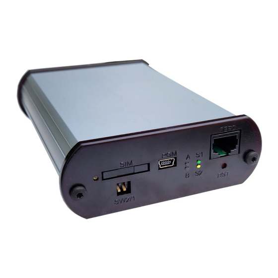
M2M Control CX630 Technical Manual V1.01 Advanced Automotive M2MI/IoT Gateway Graphical Overview A graphical overview of the front- and back are shown below: SER2 BT Antenna GNSS Antenna Cell Antenna X3: I/O Service Port SIM Card Reader Eject Button X2: COM... -
Page 12: External Connections
M2M Control CX630 Technical Manual V1.01 Advanced Automotive M2MI/IoT Gateway External connections Connections to external equipment are made via the connectors located on the back and front of the CX630. The front panel is equipped with connectors commonly accessed by the user: SIM-Card, DIP- switch, Service/programming port, LED's, RS232 and the reset button. -
Page 13: Connector X2: 12 Pin Com Connector
M2M Control CX630 Technical Manual V1.01 Advanced Automotive M2MI/IoT Gateway Connector X2: 12 pin COM connector 1W-LED 1WIRE CAN1-L CAN1-H DIN6 RS485A DC-Out RS485B Name Description 1WIRE 1-Wire bus Signal Ground CAN1-H CAN-bus 1 H-signal DIN6 Digital input 6 RS485A... -
Page 14: Connector X3: 16 Pin I/O Connector
M2M Control CX630 Technical Manual V1.01 Advanced Automotive M2MI/IoT Gateway Connector X3: 16 pin I/O connector AIN2 AGND AIN1 AGND DIN5 DIN3 5 13 DIN4 4 12 DIN1 3 11 DIN2 DOUT3 2 10 DOUT4 DOUT1 DOUT2 Name Description DOUT 1... -
Page 15: Connector X4: 6 Pin Ser1 Connector
M2M Control CX630 Technical Manual V1.01 Advanced Automotive M2MI/IoT Gateway Connector X4: 6 pin SER1 connector CAN2-H CAN2-L Name Description Transmit Data from serial port 1, RS232 compatible CAN2-H CAN-bus 2 H-signal CAN2-L CAN-bus 2 L-signal Receive Data for serial port 1, RS232 compatible... -
Page 16: Power Supply
Advanced Automotive M2MI/IoT Gateway Power Supply The M2M CONTROL CX630 device must be supplied with 8..36 VDC from an external DC power source connected to the X1 connector. Positive power is applied to the SUPP pin, and the ground is connected to the PGND pin. -
Page 17: Digital Outputs
The maximum switchable inductance is 20mH and must not be exceeded. The digital outputs are supplied through the X1 power connector that also supplies the rest of the CX630 unit. As the power is also the M2M CONTROL CX630 main power, a power fail would also affect the digital outputs. -
Page 18: Digital Inputs / Ignition Input
M2M Control CX630 Technical Manual V1.01 Advanced Automotive M2MI/IoT Gateway Digital Inputs / Ignition Input The digital inputs are all low-pass filtered and transient-protected. To activate the inputs, connect a positive voltage between the input and the GND connector. Please note: The DIN 5/IGN input is special as it also functions as the ignition input. If the ignition input is activated with a logical high or low (Wait for Event mode only), it will wake up the unit when the CX630 is in low power mode. -
Page 19: Analog Inputs / Flex Inputs
Advanced Automotive M2MI/IoT Gateway Analog Inputs / Flex Inputs The M2M CONTROL CX630 has two analog inputs. The analog inputs are voltage inputs specified with an operating range of 0V to 30V DC. The conversion resolution is up to 12 bit(0..4095). - Page 20 M2M Control CX630 Technical Manual V1.01 Advanced Automotive M2MI/IoT Gateway The analog inputs are made available at the same time as both normal analog inputs with an operating voltage range of 0-10V DC, and as flex inputs. When used as flex inputs, the inputs are multi-mode inputs that can be configured to operate as either analog or digital inputs.
-
Page 21: Can Communication Port
M2M Control CX630 Technical Manual V1.01 Advanced Automotive M2MI/IoT Gateway CAN communication port The CX630 provides the physical layer for the CAN (Controller Area Network) serial communication interface in accordance with the ISO 11898 standard. The CAN bus is designed for high-speed (up to 1Mbit) robust communication in especially harsh environments like those found in the automotive industry. -
Page 22: Rs232 Port 1
M2M Control CX630 Technical Manual V1.01 Advanced Automotive M2MI/IoT Gateway RS232 port 1 This port can be used as a general-purpose RS232 serial port without hardware handshake signals. X4: 6 pin SER1 connector overview. Name Description Transmit Data from serial port 1, RS232 compatible... -
Page 23: Rs485 Communication Ports (Eia/Tia-485-A Compatible)
If the M2M CONTROL CX630 is used as an endpoint node, the software jumper for both RS485 ports separately can be activated through the user application in order to terminate the RS485 communication lines with 120Ω. -
Page 24: 1-Wire Bus
M2M Control CX630 Technical Manual V1.01 Advanced Automotive M2MI/IoT Gateway 1-Wire bus The 1-Wire bus is available on the X2 connector. All 1-Wire communication goes through a single connection, and all 1-Wire devices connected to this connection retrieves its power directly from the bus (called parasitic power). -
Page 25: 3D Movement Sensor
Advanced Automotive M2MI/IoT Gateway 3D Movement Sensor The M2M CONTROL CX630 unit contains a 3-axis accelerometer and 3-axis gyroscope in order to detect both vibration and motion. This sophisticated range of movement sensors allows for detecting movement and position change in 3 directions, X-Y-Z with force as high as 16g in acceleration, 2000 dps in rotation. -
Page 26: Led Indicators
M2M Control CX630 Technical Manual V1.01 Advanced Automotive M2MI/IoT Gateway LED Indicators Four bi-colored (red and green) LED indicators are present on the front of the unit (see the graphical overview). Two bi-colored LED (A and B) are available to the user, and the remaining two LEDs (S1 and S2) signal the status and possible errors of the CX630 device. - Page 27 M2M Control CX630 Technical Manual V1.01 Advanced Automotive M2MI/IoT Gateway S1: System LED1 pattern overview Pattern Description Fastest blinking, green The device is initializing, preparing to start the application. Fast blinking, green The device is installing an update. Depending on the kind of S2 On, green update, it may take some time.
-
Page 28: Switches
Advanced Automotive M2MI/IoT Gateway Switches User DIP-Switch The M2M CONTROL CX630 unit contains a user-accessible DIP switch with two switches. The DIP-switch is located on the front panel for easy user access (see the graphical view). System Switch (RST) The M2M CONTROL CX630 device contains a combined reset/diagnostic switch. This switch is accessible from the front of the unit (see the graphical overview). -
Page 29: Internal Li-Ion Battery
Do not expose the device to water, saltwater or allow the battery to get wet. • Avoid strong impacts and shocks. For more information regarding the environmental limitations, see “Specifications for M2M CONTROL CX630” below or consult the M2M CONTROL CX630 datasheet. Page 29 of 41... -
Page 30: Wireless Communication
The Cellular Engine is designed for Worldwide deployment. Bluetooth LE The M2M CONTROL CX630 has an on-board Bluetooth LE 5.3 radio operating at the standard 2.4 GHz spectrum. Please consult the M2M CONTROL IDE for details on the application usage. -
Page 31: Multi Gnss Receiver
(without AGNSS) Warm start: 16 sec. • Hot start: 1 sec. • Sensitivity Acquisition: -147 dBm. • Reacquisition: -159 dBm. • Tracking: -165 dBm. The M2M CONTROL CX630 is available in variants with DR and RTK. Page 31 of 41... -
Page 32: Sim-Card Readers
The M2M CONTROL CX630 is also prepared for an M2M chip internally, which shares the SIM card signals with the internal SIM-card reader. Please contact Infranet Technologies GmbH for information on this option. -
Page 33: Installing The Internal Sim-Card
M2M Control CX630 Technical Manual V1.01 Advanced Automotive M2MI/IoT Gateway Installing the Internal SIM-card In order to gain access to the internal SIM-card reader, it is necessary to disassemble the device, as described in Appendix A. Internal SIM- Card reader The SIM card reader is lid-based with a mechanical lock to secure a safe installation. -
Page 34: Antennas
Antennas Cellular Antenna The M2M CONTROL CX630 device contains an SMA female connector for connecting a suitable LTE-compliant antenna. When installing the antenna, please ensure that the antenna is not close to metallic parts or anything else which can influence the antenna's efficiency. -
Page 35: Product Identification Label With Barcode
Advanced Automotive M2MI/IoT Gateway Product Identification Label with Barcode The M2M CONTROL CX630 product identification on the device's exterior contains a unique serial number in readable form and a barcode. The first three digits in the serial number identify the device type, and for the M2M CONTROL CX630 evaluation device, this unique code is 376 or 377. -
Page 36: Power Consumption
M2M Control CX630 Technical Manual V1.01 Advanced Automotive M2MI/IoT Gateway Power Consumption The table below shows detailed information about the M2M CONTROL CX630 device's typical power consumption while operating. Typical power consumption: Device operating in normal mode Device active Device active with Cellular on*... -
Page 37: Appendices
Appendices Appendix A – Opening the Device We recommend not disassembling the M2M CONTROL CX630 device, and the only situation where this is required is to gain access to the internal SIM card reader. The following steps describe the process. -
Page 38: Appendix B - Configuration Dip-Switches
M2M Control CX630 Technical Manual V1.01 Advanced Automotive M2MI/IoT Gateway Appendix B – Configuration DIP-switches The configuration jumper DIP-switch is located near the front side of the board, behind the front panel. To gain access it is necessary to remove the front end-cap using a Torx TX10 screwdriver. -
Page 39: Appendix C - Open Source Disclaimer
Advanced Automotive M2MI/IoT Gateway Appendix C - Open Source Disclaimer The M2M CONTROL CX630 products include several open-source software tools. This open- source software is governed by the terms and conditions of the applicable open-source license. You are bound by the terms and conditions of the appropriate open-source license in connection with your use and distribution of the open-source software in this product. -
Page 40: M2M Control Cx630 Specifications
M2M Control CX630 Technical Manual V1.01 Advanced Automotive M2MI/IoT Gateway M2M CONTROL CX630 Specifications Technical data are subject to changes. Page 40 of 41... - Page 41 M2M Control CX630 Technical Manual V1.01 Advanced Automotive M2MI/IoT Gateway * * * END OF DOCUMENT * * * * Page 41 of 41...
Need help?
Do you have a question about the M2M CONTROL CX630 and is the answer not in the manual?
Questions and answers