
Related Manuals for Infranet Technologies M2M CONTROL C660


Summary of Contents for Infranet Technologies M2M CONTROL C660
- Page 1 M2M CONTROL C660 Technical Manual Version 2.0 Infranet Technologies GmbH, Tempowerkring 19, 21079 Hamburg, Germany, Fon: +49 40 696 47 – 260, support@m2mcontrol.de...
-
Page 2: Introduction
M2M Control C660 please refer to the M2M CONTROL IDE documentation. The M2M Control C660 adds a new chapter to the highly successful era of the C6xx series offering a wide range of new features and performance improvements while still resting on the proven track record and confidence of the M2M Control C600 series. -
Page 3: The Technical Highlights Of The M2M Control C660
M2M CONTROL C660 - Technical Manual V2.00 The technical highlights of the M2M Control C660: Based on the M2M CONTROL RTCU Platform. NX32 execution architecture. o M2M CONTROL IDE development tool with full a featured device simulator. o Huge standard API with more than 800+ functions. - Page 4 M2M CONTROL C660 - Technical Manual V2.00 * * * * THIS PAGE IS INTENTIONALLY LEFT BLANK * * * www.m2mcontrol.de support@m2mcontrol.de Page 4 of 36...
-
Page 5: Table Of Contents
M2M CONTROL C660 - Technical Manual V2.00 Table of Contents Introduction ..............................2 The technical highlights of the M2M Control C660: ................... 3 Table of Contents ............................. 5 Graphical view ..............................6 External connections ............................6 Overview ..............................7 Accessories for cable assembly ........................9 Power supply ............................. -
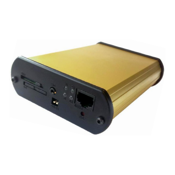
Page 6: Graphical View
M2M CONTROL C660 - Technical Manual V2.00 Graphical view www.m2mcontrol.de support@m2mcontrol.de Page 6 of 36... -
Page 7: External Connections
M2M CONTROL C660 - Technical Manual V2.00 External connections Overview Connections to external equipment are done via the connectors located on the back and front of the M2M Control C660. The front panel is equipped with connectors commonly accessed by the user: SIM-Card, SD- CARD, DIP-Switch, Headset, LED’s and RS232. - Page 8 M2M CONTROL C660 - Technical Manual V2.00 Connector X1: 4 pin PWR connector overview Name Description SUPP Power supply, positive (+) connection DI5/IGN Digital input 5 / Ignition input (Shared with X3) SUPP Power supply, positive (+) connection PGND Power Ground...
-
Page 9: Accessories For Cable Assembly
M2M CONTROL C660 - Technical Manual V2.00 Connector X4: 6 pin SER1 connector overview Name Description Transmit Data from serial port 1, RS232 compatible RS-DET Programming cable detect, normally unconnected (if programming cable, connect to GND) DC-Out +3.3V/150mA DC-Out for external equipment. -
Page 10: Power Supply
M2M CONTROL C660 - Technical Manual V2.00 Power supply The M2M Control C660 device must be supplied with 8..36 VDC from an external DC power source connected to the X1 connector. Positive power is applied to the SUPP pin, and ground is connected to the PGND pin. -
Page 11: Digital Outputs
The maximum switchable inductance is 20mH and must not be exceeded. The digital outputs are supplied through the X1 power connector that also supplies the rest of the C660 unit. As the power is also the M2M Control C660 main power, a power-fail would also affect the digital outputs. -
Page 12: Digital Inputs / Ignition Input
M2M CONTROL C660 - Technical Manual V2.00 Digital Inputs / Ignition Input The digital inputs are all low-pass filtered and transient protected. To activate the inputs, connect a positive voltage between the input and the GND connector. Please note: The DIN 5/IGN input is a special input as it also functions as the ignition input. If the ignition input is activated with a logical high or low (Wait For Event mode only), when the C660 is in low power mode, it will wake-up the unit. -
Page 13: Analog Inputs
M2M CONTROL C660 - Technical Manual V2.00 Analog Inputs There are two analog inputs available on the unit. The analog inputs are voltage inputs specified with an operating range of 0V to 10V DC. The conversion resolution is 12 bit +/- 1.5% FSR @ 25 degrees ˚C. -
Page 14: Rs232 Port 1 / Programming Port
M2M CONTROL C660 - Technical Manual V2.00 RS232 port 1 / programming port This port can be used as general-purpose RS232 serial port or as a programming port. In order to use the port for programming, the RS-DET pin must be connected to GND. When using the port as general-purpose RS232, the RS-DET pin must be left unconnected. -
Page 15: Rs485
M2M CONTROL C660 - Technical Manual V2.00 RS485 RS485 is available on the X2 connector as serial port 1. The RS485 bus a multi-drop network with a maximum of 32 units connected simultaneously to the bus. The RS485 bus contains an RS485+... -
Page 16: Can
M2M CONTROL C660 - Technical Manual V2.00 The M2M Control C660 provides the physical layer for the CAN (Controller Area Network) serial communication interface in accordance with the ISO 11898 standard. The CAN bus is designed for high-speed (up to 1Mbit) robust communication in especially harsh environments like those found in the automotive industry. -
Page 17: 1-Wire Bus
M2M CONTROL C660 - Technical Manual V2.00 1-Wire bus The 1-Wire bus is available on the X2 connector. All 1-Wire communication goes through a single connection, and all 1-Wire devices connected to this connection retrieves its power directly from the bus (called parasitic power). For this only two wires are needed – the 1-wire signal and the ground reference –... -
Page 18: Hands-Free Connector
M2M CONTROL C660 - Technical Manual V2.00 Hands-free connector The C660 unit has a 4-pole 2.5mm jack connector for connecting a hands-free set to the built-in GSM modem. The speaker output is amplified through the internal Class-D amplifier and is a differential (balanced) signal. -
Page 19: 3D Movement Sensor
M2M CONTROL C660 - Technical Manual V2.00 3D movement sensor The M2M Control C660 unit contains a 3-axis accelerometer in order to detect both vibration and motion. It makes it possible to detect movement and position change in 3 directions, X-Y-Z with a force as high as 16g. -
Page 20: Led Indicators
M2M CONTROL C660 - Technical Manual V2.00 LED Indicators Three bi-colored (red and green) and a single yellow LED indicator are present on the front of the unit (see graphical view). Two bi-colored LED’s (A and B) are available to the user and the remaining two LED’s (S1 and S2) are signaling the status and possible errors of the C660 unit. -
Page 21: System Led S1 And S2
M2M CONTROL C660 - Technical Manual V2.00 System LED S1 and S2 The C660 is equipped with two system LED’s which shows the status and possible errors of the C660 unit. The different patterns are listed in the table below. If the color of the system LED S1 is yellow, the unit is actively communicating with the M2M CONTROL IDE (or another program, supporting the RTCU RACP protocol). -
Page 22: Switches
M2M CONTROL C660 - Technical Manual V2.00 Switches DIP-switch The M2M Control C660 unit contains a dipswitch with two switches. The dipswitch is located on the front panel for easy user access (see the graphical view). System switch (RST) The M2M Control C660 unit contains a combined reset/diagnostic switch. This switch is accessible from the front of the unit (see graphical view) It is necessary to use a small thin object with a diameter of approx. -
Page 23: Internal Li-Ion Battery
M2M CONTROL C660 - Technical Manual V2.00 Internal Li-Ion battery The C660 contains an internal Li-Ion battery for operation even when the external power is absent making it possible to report power loss etc. Please note that when external power is removed, the unit will be powered down by default. -
Page 24: Internal / External Sim-Card Readers
M2M CONTROL C660 - Technical Manual V2.00 Internal / External SIM-card readers The M2M Control C660 unit contains both an internal and an external standard SIM card reader. The external reader is located on the front panel (please see the graphical view) and is easily accessed. -
Page 25: Installing The Internal Sim-Card
Please refer to Appendix B for detailed description of installing the internal SIM-card. SD-CARD reader The M2M Control C660 unit has a standard SD-CARD reader with a FAT32 file-system support for standard PC-compatibility, with up to 32 GB capacity support. -
Page 26: Installing The Sd-Card
M2M CONTROL C660 - Technical Manual V2.00 The differences in write endurance between commercial grade MLC flash and ATP Industrial grade SLC flash is quite remarkable for write-intensive applications: Total Writeable Data Time Prediction Details Product Line Prediction @ 1GB... -
Page 27: Antennas
The barcode found on the C660 unit contains the serial number. The first three digits in the serial- number identify the unit type. For the M2M Control C660 this unique code is 288 . The barcode format used: 2/5 Interleaved with Check Digit www.m2mcontrol.de... -
Page 28: Power Consumption
M2M CONTROL C660 - Technical Manual V2.00 Power consumption Detailed information on the maximum power consumption of the C660 unit in different states and at different supply voltages is listed below. Maximum power consumption: Unit running on external supply Unit Active... -
Page 29: Specification For The 99-Channels Multi-Gnss Receiver
M2M CONTROL C660 - Technical Manual V2.00 Specification for the 99-channels multi-GNSS receiver MediaTek MT3333 Single Chip Super Sensitivity General: 99 acquisition / 33 tracking / up to 210 PRN channels. Multi GNSS engine for GPS, GLONASS and QZSS Support DGPS, SBAS(WAAS,EGNOS,MSAS,GAGAN). -
Page 30: Appendix A - Assembling/Disassembling Of The Unit
M2M CONTROL C660 - Technical Manual V2.00 Appendix A – Assembling/disassembling of the unit The CAN write enable jumper and a SIM-card reader are located inside of the unit. In order to gain access to these interfaces, it is necessary to remove the internal board from the aluminum encapsulation. -
Page 31: Appendix B - Installing A Sim-Card Into The Internal Sim-Card Reader
M2M CONTROL C660 - Technical Manual V2.00 Appendix B – Installing a SIM-card into the internal SIM-card reader To get access to the internal SIM-card reader it is necessary to disassembly the device as described in Appendix A. Internal SIM-card reader The SIM card reader is a lid based type with a mechanical lock to secure a safe installation. - Page 32 M2M CONTROL C660 - Technical Manual V2.00 SIM card orientation Lock Open SIM inserted and locked www.m2mcontrol.de support@m2mcontrol.de Page 32 of 36...
-
Page 33: Appendix C - Enabling The Can Bus Write Capability
M2M CONTROL C660 - Technical Manual V2.00 Appendix C – Enabling the CAN bus Write capability Connecting the C660 to a CAN network can be dangerous. If the C660 is not configured with the correct network parameters, it can lead to network corruption and may interfere with other connected equipment on the bus. - Page 34 M2M CONTROL C660 - Technical Manual V2.00 3. Install the jumper as shown above 4. Mount the end-panel and secure it with the screws. www.m2mcontrol.de support@m2mcontrol.de Page 34 of 36...
-
Page 35: M2M Control C660 Specifications
M2M CONTROL C660 - Technical Manual V2.00 M2M Control C660 Specifications Technical data are subject to changes. www.m2mcontrol.de support@m2mcontrol.de Page 35 of 36... - Page 36 M2M CONTROL C660 - Technical Manual V2.00 www.m2mcontrol.de support@m2mcontrol.de Page 36 of 36...
Need help?
Do you have a question about the M2M CONTROL C660 and is the answer not in the manual?
Questions and answers