
Related Manuals for Siemens PTS 5


Summary of Contents for Siemens PTS 5
- Page 1 SIEMENS PTS 5 User Manual 18-838-728-502 Issue 888.902.6111 www.intellirentco.com...
-
Page 2: Table Of Contents
INFORMATION BE DESIRED OR SHOULD PARTICULAR PROBLEMS ARISE WHICH ARE NOT COVERED SUFFICIENTLY FOR THE PURCHASERS'S PURPOSES. THE MATTER SHOULD BE REFERRED TO THE LOCAL SIEMENS SALES OFFICE. THE CONTENTS OF THIS INSTRUCTION MANUAL SHAll NOT BECOME PART OF OR MODIFY ANY PRIOR OR EXISTING AGREEMENT. -
Page 3: Introduction
Introduction THIS EQUIPMENT CONTAINS HAZARDOUS VOLTAGES. DEATH, SERIOUS PERSONAL INJURY, OR PROPERTY DAMAGE CAN RESULT IF SAFETY INSTRUCTIONS ARE NOT FOLLOWED. ONLY QUALIFIED PERSONNEL SHOULD WORK ON OR AROUND THIS EQUIPMENT AFTER BECOMING THOROUGHLY FAMILIAR WITH ALL WARNINGS AND SAFETY NOTICES CONTAINED HEREIN. THE SUCCESSFUL AND SAFE OPERATION OF THIS EQUIPMENT IS DEPENDENT UPON PROPER HANDLING, INSTALLATION AND OPERATION. -
Page 4: Safety Information
Safety Information AWARNING High Speed MOving Parts Can cause death or serious injury Discharge the springs before attempting to perform any inspection or adjustment of the circuit breaker operating mechanism. Keep hands clear of the mechanism if exercising the circuit breaker during the test Hazardous voltage Will... -
Page 5: General
The scope of this manual covers the operation of the PTS 5. Additional information on the STili may be found in publicaUon SGIM-3118C. Additional Information on the RL breaker may be found In publication SGIM-30660. -
Page 6: Controls And Indicators
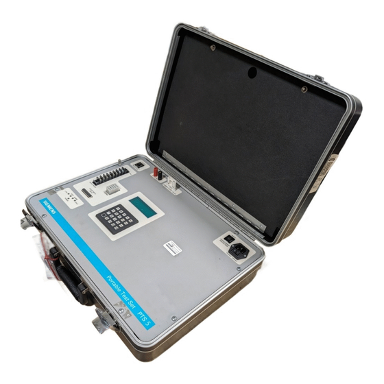
Controls and Indicators (refer to Figure for location) POWER 120 VAC and SWITCH: AUach Ihe power supply cord here. The SWITCH applies power to the unit. INPUT OVERCURRENT PROTECTION: Provides protection to the circuit in the event of internal failure. Should this breaker trip repeatedly, the unit likely has an internal fault and requires service. - Page 7 Figure 1 Panel Layout 888.902.6111 www.intellirentco.com...
- Page 8 Figure Attachment of the cable to an mounted on a breaker test STili 888.902.6111 www.intellirentco.com...
- Page 9 Figure Attachment of an STili directly to the PTS 888.902.6111 www.intellirentco.com...
-
Page 10: Test Preparation
Test Preparation " DANGER Hazardous voltage Will cause death. serious personal InJury, end/or property damage. Only qualified personnel should wori<. on this equipment, thoroughly f after becomIng warnings, with safety notices, and maintenance procedures contained hereIn and on the devices. of( power before working on this equlpmenl. -
Page 11: Ground Fault Pickup Test
Long Time Pickup (L TPU) Test Set the STill dials as follows (Ignore any that are not present the unit under test): long TIme Setting: x sensor long Time Delay: Instantaneous Pickup: x sensor Short Time Pickup: x LT setting Short Time Delay: 0.40 Ground Fault PIckup:... - Page 12 Set the STIli dials as follows (ignore any that are not present on the unit under test): Long Time Setting: 0.5 x sensor (very importantl) Long Time Delay: 30 s Instantaneous Pickup: 15 x sensor Short TIme Pickup: 2 x T setting Shol1 Time Delay: 0.40 s Ground Fault Pickup: 20%...
- Page 13 Test the remaining points on the Short Time Pickup dial. In each case, the STili should achieve STPU within the parameters listed below. To speed up the testing in the higher ranges, a starting ENTER to value closer to the minimum may be keyed in after pressing the START button. P ress load the value and start the test.
-
Page 14: Long Time Delay Test
Ground Fault Pickup (GFPU) Test (only equipped) Set the STili dials as follows (ignore any thai are not present on the unit under test): Long Time Setting: x sensor long Time Delay: Instantaneous Pickup: x sensor Short Time Pickup: x l T setting 0.40 Short Time Delay: Ground Fault Pickup:... - Page 15 Instantaneous Pickup (IPU) Test (only if equipped) Note that by nature of the Instantaneous function, pIckup causes a trip. Set the STili dials as follows (Ignore any that are not present on the unit under test): long Time Setting: 1.0 x sensor Long TIme De/ay: Instantaneous Pickup: 2 x sensor Short Time Pickup: 12 x L T setting...
- Page 16 Long Time Delay (LTD) Test tha� Set the STili dials as follows (ignore any are not present on the unit under test): Long Time Setting: x sensor long Time Delay: Instantaneous Pickup: x sensor Short Time Pickup: x LT setting 0.40 Short T1me Oelay: Ground Fault Pickup:...
-
Page 17: Short Time Delay Test
Short Time Delay (STD) Test (only equipped) Set the STili dials as follows (ignore any lhal are not present on the unit under test): Long TIme Setting: 0.5 x sensor Long lime Delay: Instantaneous Pickup: 15 x sensor Short Time Pickup: 2 x T setting Short Time Delay: 0.40 s Ground Fault Pickup: 20%... -
Page 18: Ground Fault Time Delay Test
Ground Fault Time Delay (GFTD) Test (only if equipped) als as follows (ignore any that are not present on the unit under test): Set the STIli d Long Time Setting: 0.5 x sensor Long Time Delay: 30 Instantaneous Pickup: 15 x sensor Short Time Pickup: 12 x T setting Tm&... -
Page 19: Zone Selective Interlock Tests
Zone Selective Interlock (ZSI) Tests There are two parts to the ZSI system. The first is a signal which is issued by a STili when it goes into Short Time or �round Fault pickup. The second is a signal receiver in the STili that drives the Short Time and Ground Fault delays to the minimum whenever the ZSI mode is enabled and the signal is not present. - Page 20 Set up the PTS 5 for a Short Time Delay test per the instructions above. Note that it is not necessary to actually close the breaker for these tests. The STili will Indicate its tripped status to the PTS 5 whether or not the breaker is closed.
- Page 21 The ZSI capabilities of a standalone STili may be verified by obtaining the ZSI Signal Tester, part number 18-732-790-563, from Siemens customer service. Attach the STili to the PTS either by direct connection to the terminal block, or through the test cable.
- Page 22 Thermal Memory switch is set to the IN position. To perfonn the third test, press the NEXT button to select "Thermal Memory" mode. Press the START button to begin the tesl The PTS 5 will Inject a current into the STili with the following characteristics: seconds of 0.55 A (to drive the STili Into LT Pickup)
- Page 23 This time should be longer than the other two tests, since the over1oad was nol constant. NOTE: the PTS 5 times out, with the Thermal Memory switch set to IN, then the test did not pass.
-
Page 24: Testing The Stili Actuator
Watch the actuator and press the STOP button when the breaker trips (or the plunger pops out, if bench testing). If the breaker fairs to trip. refer to the breaker instruction manual SGIM- 3068D and follow the troubleshooting instructions therein. Disconnect the actuator from the PTS 5 and perform the following resistance checks: 888.902.6111 www.intellirentco.com... - Page 25 Red lead to black lead: 1 5 -20 O. Black lead to blue lead: 40-50 O. Red lead to blue lead: 55-70 O. Any lead to ground, measured with a standard ohmmeter: infinite. If the actuator fails these tests, replace it. No attempt should be made to repair the actuator in the field.
-
Page 26: Calibration
Calibration The calibration of the current source may be checked using a precision ammeter. There are two A range, and the alher set Is for the 1.0-10 A sets of calibration points. One set is for the 0-1.5 range. Attach a known good STili the unit either using the test cables directly with the fanning strip. -
Page 27: Repair Of Static Trip Devices
Siemens representative for Instructions on returning the ether authorized service repair facility. Any efforts to aHempt to make repairs in the factory field will result in voiding all equipment warranties.
Need help?
Do you have a question about the PTS 5 and is the answer not in the manual?
Questions and answers