Behringer ULTRADRIVE PRO DCX2496, ULTRADRIVE DCX2496LE Manual
- User manual (36 pages) ,
- Sync manual (28 pages) ,
- Software manual (27 pages)
Advertisement
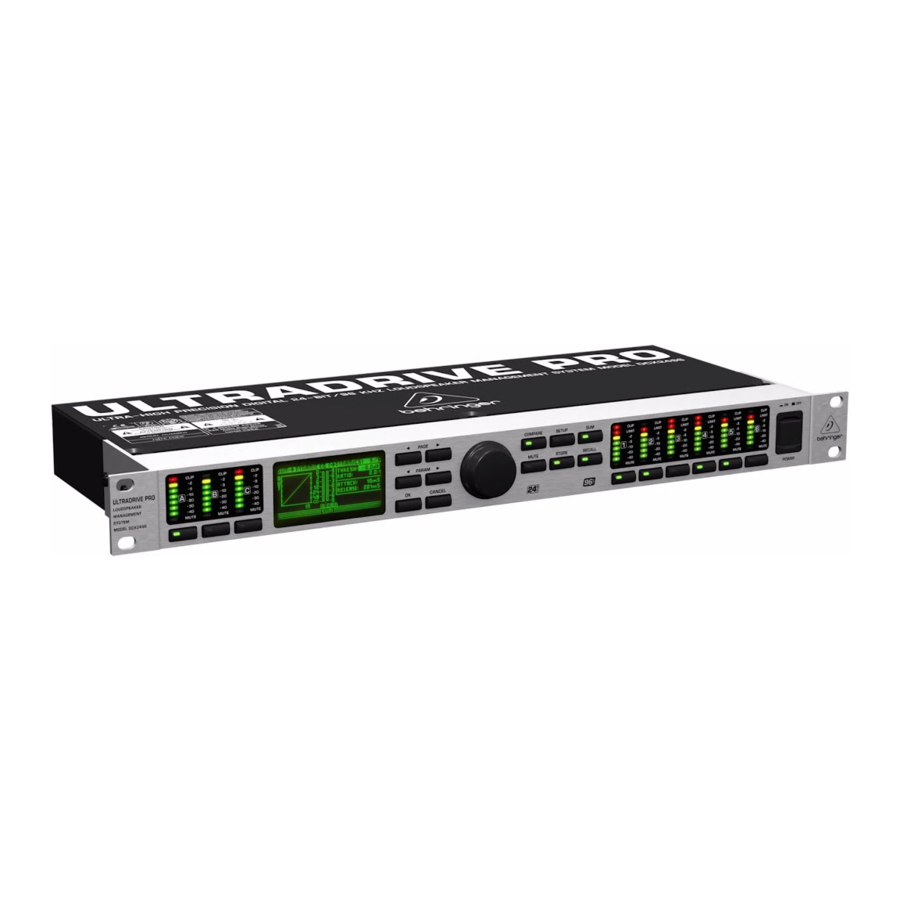
Device Controls

- The DCX2496(LE) features 6-segment LED displays (plus CLIP and MUTE LED) for precise level adjustment of input signals A-B or A-C.
- If the input stage is overdriven, the CLIP LED will indicate that the signal is distorting.
- The bottom LED (#8) is the MUTE LED (red), which illuminates when the respective input is muted.
- These are the input channel buttons, which allow you to activate specific functions from the selected menus (e.g. MUTE). Additionally, you can use these buttons to call up the IN A/B/C menus.
- The DISPLAY shows all the menus available for preset editing.
- Use these buttons to call up the DCX2496(LE)'s menus (e.g. SETUP, RECALL, etc.). The only exception is the COMPARE button, which allows you to compare the edits made with the previously selected presets. When COMPARE is active, no value changes can be entered.
- The PAGE buttons select single pages from one menu.
- Individual parameters can be selected with the PARAM buttons.
- The data wheel allows you to edit the selected parameters.
- With the OK and CANCEL buttons you can either confirm or cancel any settings made.
- Outputs 1-6 each have a 5-segment LED display (plus MUTE, CLIP and LIMIT LED) showing the respective output levels.
- Like the input stages, the output stages should not be overdriven, i.e. the CLIP LED should not illuminate.
- The LIMIT LED illuminates when the limiter for the corres ponding output has been activated and is operating.
- The bottom LED indicator (#8) is the MUTE LED, which illuminates as soon as the corresponding output is muted.
- Output channel buttons, with which you can enter the outputs 1-6 or mute or reactivate individual outputs in MUTE mode.
- Use the POWER switch to put your DCX2496(LE) into operation. The POWER switch should always be in the "Off" position when you are about to connect your unit to the mains.
- This is the FUSE HOLDER of your DCX2496(LE). Blown fuses must be replaced by a fuse of the same type and rating.
- The mains connection is an IEC receptacle. An appropriate power cord is included.
- The 9-pin RS-232 interface allows you to connect your DCX2496 to a computer. This enables you to save and load files, update the DCX2496 operating software, or remotely control one or several ULTRADRIVE PRO units from a PC. Free editor software can be downloaded at behringer.com.
- When you have daisy-chained several ULTRADRIVE PRO via the LINK connectors (see (21)), please press the TERM switch on the first and last unit of the chain, to avoid data reflections and transmission errors.
- Use the LINK connectors A and B (RS-485 network interface) and a commercially available network cable to daisy-chain several ULTRADRIVE PROs.
- Balanced XLR output connectors for output channels 1-6. Connect your power amps here.
- Balanced XLR input connectors A-B / A-C are used for connecting input signals.
DCX2496:
Input A can also be used for digital AES/EBU input signals. Input C can be used for line signals or for connecting a measuring microphone. If AUTO ALIGN has been enabled in the SETUP menu, input C will be set for mic levels automatically. Additionally, phantom power for the measuring microphone will be switched on.
Quick Start
This chapter is for those who cannot wait to use their new DCX2496(LE) in a practical application. You will find a description of how you can explore your DCX2496(LE) and its versatile and intuitive features below. This chapter is just a starting point for future excursions. So, please read the entire user's manual to take full advantage of all your DCX2496(LE)'s features and functions.
Selecting an Output Configuration

Press the SETUP button to call up the SETUP menu. On the first menu page, select an output configuration (OUT CONFI GURATION) to determine which outputs are used for which frequency ranges. One mono and three stereo configurations are available.
The mono configuration allows you to split the input signal into six different frequency ranges. The stereo configurations allow a maximum of three different frequency ranges per stereo side. The abbreviations L, M and H stand for Low, Mid and High Speaker.
Setting Crossover Frequencies

In order to assign dedicated frequency bands to the output channels, you have to define the crossover frequencies (X-Over) for each of them. The crossover frequencies determine the upper and lower limits of a frequency band, which allows you to clearly separate the outputs from each other in terms of frequency.
Press the corresponding OUT button (1-6) and select menu page 2/8 using the PAGE buttons. With the parameters FREQ and TYPE you can define the slope of the crossover frequency and also select a filter type. When the parameter X-OVER ADJUST MODE is set to "LINK", any changes to the crossover frequency will also shift the neighboring frequency ranges.
Muting Input/Output Channels

Press the MUTE button to enter the MUTE menu. Here you can mute the inputs and outputs of the DCX2496(LE). On this page you can mute or activate individual channels by pressing the channel buttons (IN A-B / A-C and OUT 1-6), or all inputs/outputs by pressing the PARAM and OK or CANCEL buttons. Thus, you can monitor each frequency band, either individually or together with a neighboring band, to allow perfect editing of the isolated frequency range. To quit the MUTE menu press MUTE a second time.
Storing Presets

Use the STORE button to save your presets.
Recalling Presets

Press the RECALL button to load presets from the internal memory. Select the preset you wish to recall, then press ENTER. We included some typical presets that you can use as a basis for your own applications.
Restoring the Factory Presets
If you wish to restore the ULTRADRIVE's factory presets, press and hold both PAGE buttons on the front panel switching on the unit. The DCX2496(LE) prompts you to confirm (OK) or CANCEL. Press OK to erase the internal memory and restore the factory presets.
Specifications
| Analog Inputs (A, B, C) | |
| Type | electronically balanced |
| Connector | XLR |
| Max. input level | +22 dBu |
| Input impedance | approx. 35 kΩ @ 1 kHz |
| Crosstalk | -72 dB @ 0 dBu |
| Digital Input (A) - DCX2496 | |
| Connector | XLR |
| Format | S/PDIF or AES/EBU |
| Input level | 0.3 to 10 Vpp |
| Input impedance | approx. 110 Ω |
| Sampling frequency | 32 to 96 kHz |
| Special feature | Sample Rate Converter |
| Microphone Input (C) - DCX2496 | |
| Type | electronically balanced |
| Connector | XLR |
| Max. input level | -23 dBu |
| Input impedance | approx. 670 Ω @ 1 kHz |
| Phantom supply | +15 V |
| Analog Outputs (1, 2, 3, 4, 5, 6) | |
| Type | electronically balanced |
| Connector | XLR |
| Max. output level | +22 dBu |
| Output impedance | approx. 100 Ω @ 1 kHz |
| Crosstalk | -100 dB @ 10 dBu |
| System Data | |
| Sampling frequency | 96 kHz |
| Signal delay | < 1 ms Analog input to analog output |
| Frequency response | 10 Hz to 45 kHz (-3 dB) typ. |
| Dynamic range | 112 dB |
| THD+N Ratio | 0,007% @ 0 dBu 0,004% @ 10 dBu |
| Converters | |
| A/D Converter CS5381 | |
| Resolution | 24-Bit Delta-Sigma |
| Oversampling | 64x |
| Dynamic range | 120 dB typ. |
| D/A Converter AK4393 | |
| Resolution | 24-Bit Delta-Sigma |
| Oversampling | 64x |
| Dynamic range | 120 dB typ. |
| Serial Interface (DCX2496) | |
| RS-232 | |
| Type | 9-pin sub-D connector |
| Transmission type | 115200 bauds, 8 data bits, 1 stop bit, no parity |
| RS-485 (2x) | |
| Type | RJ-45 connector |
| Transmission type | 38400 bauds, 8 data bits, 1 stop bit, no parity |
| Power Supply | |
| Mains Voltage | |
| USA/Canada | 120 V~, 60 Hz |
| Europe/U.K./Australia | 230 V~, 50 Hz |
| Japan | 100 V~, 50 - 60 Hz |
| General export model | 100 - 240 V~, 50 - 60 Hz |
| Power consumption | approx. 12 W |
| Fuse | 100 to 240 V~: T 1 A H |
| Mains connector | Standard IEC receptacle |
| Dimensions/Weight | |
| Dimensions (H x D x W) | 45 x 483 x 208 mm (1.75 x 19 x 8.1") |
| Weight | approx. 2 kg (4.4 lbs) |
| Shipping Weight | approx. 3.2 kg (7 lbs) |
Other important information
- Register online. Please register your new Music Tribe equipment right after you purchase it by visiting musictribe.com. Registering your purchase using our simple online form helps us to process your repair claims more quickly and efficiently. Also, read the terms and conditions of our warranty, if applicable.
- Malfunction. Should your Music Tribe Authorized Reseller not be located in your vicinity, you may contact the Music Tribe Authorized Fulfiller for your country listed under "Support" at musictribe.com. Should your country not be listed, please check if your problem can be dealt with by our "Online Support" which may also be found under "Support" at musictribe.com. Alternatively, please submit an online warranty claim at musictribe.com BEFORE returning the product.
- Power Connections. Before plugging the unit into a power socket, please make sure you are using the correct mains voltage for your particular model. Faulty fuses must be replaced with fuses of the same type and rating without exception.
Important Safety Instructions

RISK OF ELECTRIC SHOCK!
DO NOT OPEN!
 Terminals marked with this symbol carry electrical current of sufficient magnitude to constitute risk of electric shock. Use only high-quality professional speaker cables with ¼" TS or twist-locking plugs pre-installed. All other installation or modification should be performed only by qualified personnel.
This symbol, wherever it appears, alerts you to the presence of uninsulated dangerous voltage inside the enclosure - voltage that may be sufficient to constitute a risk of shock.
 This symbol, wherever it appears, alerts you to important operating and maintenance instructions in the accompanying literature. Please read the manual.
To reduce the risk of electric shock, do not remove the top cover (or the rear section). No user serviceable parts inside. Refer servicing to

To reduce the risk of fire or electric shock, do not expose this appliance to rain and moisture. The apparatus shall not be exposed to dripping or splashing liquids and no objects filled with liquids, such as vases, shall be placed on the apparatus.
These service instructions are for use by qualified service personnel only. To reduce the risk of electric shock do not perform any servicing other than that contained in the operation instructions. Repairs have to be performed by qualified service personnel.
- Read these instructions.
- Keep these instructions.
- Heed all warnings.
- Follow all instructions.
- Do not use this apparatus near water.
- Clean only with dry cloth.
- Do not block any ventilation openings. Install in accordance with the manufacturer's instructions.
- Do not install near any heat sources such as radiators, heat registers, stoves, or other apparatus (including amplifiers) that produce heat.
- Do not defeat the safety purpose of the polarized or grounding-type plug. A polarized plug has two blades with one wider than the other. A grounding-type plug has two blades and a third grounding prong. The wide blade or the third prong are provided for your safety. If the provided plug does not fit into your outlet, consult an electrician for replacement of the obsolete outlet.
- Protect the power cord from being walked on or pinched particularly at plugs, convenience receptacles, and the point where they exit from the apparatus.
- Use only attachments/accessories specified by the manufacturer.
- Use only with the cart, stand, tripod, bracket, or table specified by the manufacturer, or sold with the apparatus. When a cart is used, use caution when moving the cart/apparatus combination to avoid injury from tip-over.
![]()
- Unplug this apparatus during lightning storms or when unused for long periods of time.
- Refer all servicing to qualified service personnel. Servicing is required when the apparatus has been damaged in any way, such as power supply cord or plug is damaged, liquid has been spilled or objects have fallen into the apparatus, the apparatus has been exposed to rain or moisture, does not operate normally, or has been dropped.
- The apparatus shall be connected to a MAINS socket outlet with a protective earthing connection.
- Where the MAINS plug or an appliance coupler is used as the disconnect device, the disconnect device shall remain readily operable.
- Do not install in a confined space, such as a book case or similar unit.
- Do not place naked flame sources, such as lighted candles, on the apparatus.
- Please keep the environmental aspects of battery disposal in mind. Batteries must be disposed-of at a battery collection point.
- This apparatus may be used in tropical and moderate climates up to 45°C.

Documents / Resources
References
Download manual
Here you can download full pdf version of manual, it may contain additional safety instructions, warranty information, FCC rules, etc.
Download Behringer ULTRADRIVE PRO DCX2496, ULTRADRIVE DCX2496LE Manual
Advertisement


Need help?
Do you have a question about the ULTRADRIVE PRO DCX2496 and is the answer not in the manual?
Questions and answers