Siemens SITRANS P, SITRANS LH100 Manual
- Operating instructions manual (280 pages) ,
- Brochure & specs (234 pages) ,
- Compact operating instructions (94 pages)
Advertisement
![]()
Introduction
Purpose of this documentation
These instructions contain all information required to commission and use the device. Read the instructions carefully prior to installation and commissioning. In order to use the device correctly, first review its principle of operation.
The instructions are aimed at persons mechanically installing the device, connecting it electronically, configuring the parameters and commissioning it, as well as service and maintenance engineers.
Checking the consignment
- Check the packaging and the delivered items for visible damages.
- Report any claims for damages immediately to the shipping company.
- Retain damaged parts for clarification.
- Check the scope of delivery by comparing your order to the shipping documents for correctness and completeness.

Using a damaged or incomplete device
Risk of explosion in hazardous areas.
- Do not use damaged or incomplete devices.
Transportation and storage
To guarantee sufficient protection during transport and storage, observe the following:
- Keep the original packaging for subsequent transportation.
- Devices/replacement parts should be returned in their original packaging.
- If the original packaging is no longer available, ensure that all shipments are properly packaged to provide sufficient protection during transport. Siemens cannot assume liability for any costs associated with transportation damages.
 NOTICE
Insufficient protection during storage
The packaging only provides limited protection against moisture and infiltration.
- Provide additional packaging as necessary.
Special conditions for storage and transportation of the device are listed in Technical specifications.
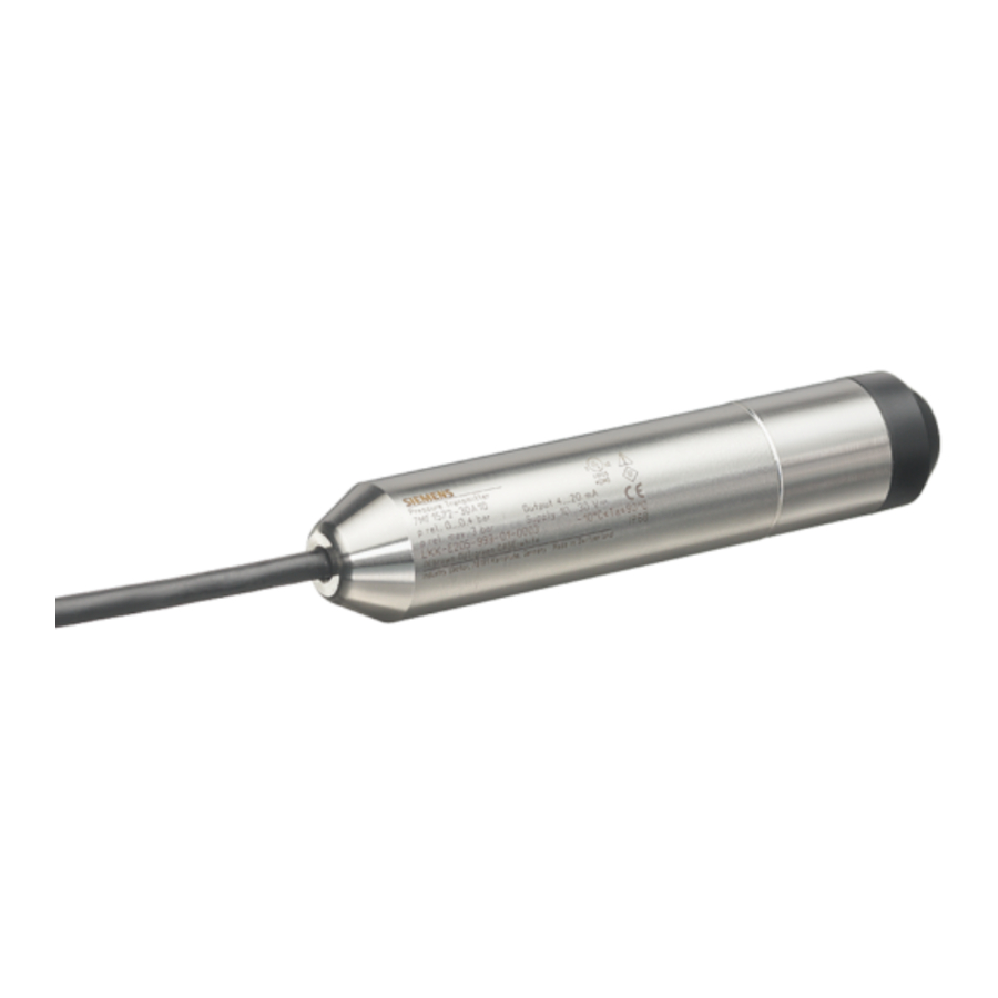
Description
Application range
The pressure transmitter LH100 is a submersible sensor for hydrostatic level measurement. The pressure transmitter measures the liquid levels in tanks, containers, channels and dams.
The pressure transmitter is available for various measuring ranges and optionally with explosion protection. A cable box and an anchor clamp are available as accessories to make installation easier.
The pressure transmitter is used, for example, in the following industrial areas:
- Water supply
- For use in pressureless/open tanks and wells
Structure
The pressure transmitter has a built-in ceramic sensor which is equipped with a Wheatstone resistance bridge.
The pressure transmitter is equipped with electronics that is installed, together with the sensor, in a stainless steel enclosure. There is also a vent pipe in the connecting cable.
The measuring diaphragm is effectively protected against external influences by a protective cover.
The sensor, the electronics and the connecting cable are housed in an enclosure with small dimensions.
The pressure transmitter is compensated for a wide temperature range.
Design of the nameplate
The pressure transmitter has a nameplate with the article number and other important information, such as design details and technical specifications.
You must also observe the information in the relevant certificate for a transmitter version for use in hazardous areas.

- Article number
- Characteristics for hazardous area
- Serial number
- Category for operating area
- Type of protection
- Group (gas, dust)
- Maximum surface temperature (temperature class)
- Group (gas)
Figure 3-1 Example of a nameplate
Mode of operation

- Sensor
- Connection for auxiliary power supply
- Vent pipe
- Protective conductor connection/ Equipotential bonding
- Hydrostatic pressure
Figure 3-2 Pressure transmitter, mode of operation and wiring diagram
On one side of the sensor  the diaphragm is exposed to the hydrostatic pressure
  , which is proportional to the immersion depth. This pressure is compared with the atmospheric pressure. Pressure compensation is carried out using the vent pipe
  in the connecting cable.
The hydrostatic pressure of the liquid column acts on the diaphragm of the sensor and transmits the pressure to the Wheatstone resistance bridge in the sensor.
The output voltage signal of the sensor is fed to the electronics, where it is converted into an output current signal of 4 mA to 20 mA.
The protective conductor connection/equipotential bonding  is connected to the enclosure.
Installing/mounting
Basic safety instructions
Wetted parts unsuitable for the process media
Risk of injury or damage to device.
Hot, toxic and corrosive media could be released if the process medium is unsuitable for the wetted parts.
- Ensure that the material of the device parts wetted by the process medium is suitable for the medium. Refer to the information in Technical specifications.
Note
Material compatibility
Siemens can provide you with support concerning selection of sensor components wetted by process media. However, you are responsible for the selection of components. Siemens accepts no liability for faults or failures resulting from incompatible materials.
Exceeded maximum ambient or process media temperature Danger of explosion in hazardous areas.
Device damage.
- Make sure that the maximum permissible ambient and process media temperatures of the device are not exceeded. Refer to the information in Technical specifications.
NOTICE
Using a device with frozen process medium
Damage to the device through ice formation.
- Prevent ice formation on the pressure transmitter. The process medium must not freeze
Proper mounting
NOTICE
Incorrect mounting
The device can be damaged, destroyed, or its functionality impaired through improper mounting.
- Before installing ensure there is no visible damage to the device.
- Make sure that process connectors are clean, and suitable gaskets and glands are used.
- Mount the device using suitable tools. Refer to the information in Technical specifications.

Loss of type of protection
Damage to device if the enclosure is open or not properly closed. The type of protection specified on the nameplate or in Technical specifications is no longer guaranteed.
- Make sure that the device is securely closed.
Installation

- Distance from the start of the protective cover to the height of the measuring diaphragm
- Distance from the start of the thread pick-up to the height of the measuring diaphragm (version without protective cover)
- Measurement reference height
- Level
Figure 4-1 Mounting the pressure transmitter, dimensions in mm
- Install the pressure transmitter suspended downward on the cable.
- To prevent measuring errors, fasten the pressure transmitter for moved process media.
- Fasten the pressure transmitter by means of a guide tube or an additional weight on the transmitter (max. tensile force on connecting cable 250 N).
- Fasten the cable above the container with the anchor clamp.
- Connect the cable itself with the cable box.
- Mount the cable box at a location appropriate to its degree of protection (IP66) in the vicinity of the measuring point.
- To ensure proper functioning, make sure that the entry openings on the protective cover of the pressure transmitter do not get soiled and that the process medium does not freeze.
Setting up the measuring points

- Cable box
- Anchor clamp
- Pressure transmitter
Figure 4-2 Basic procedure for setting up the measuring points
Establishing the measuring range
Calculating the measuring range with process media with a density ≠ 1000 kg/m3 (process medium ≠ water)
p = ρ * g * h
with:
ρ = density of the process medium
g = local gravitational acceleration
h = maximum level
Connecting
Basic safety instructions
Unsuitable cables, cable glands and/or plugs
Risk of explosion in hazardous areas.
- Use only cable glands/plugs that comply with the requirements for the relevant type of protection.
- Tighten the cable glands in accordance with the torques specified in Technical specifications.
- Close unused cable inlets for the electrical connections.
- When replacing cable, glands use only cable glands of the same type.
- After installation, check that the cables are seated firmly.
Improper power supply
Risk of explosion in hazardous areas and loss of device safety as a result of incorrect power supply, e.g. using direct current instead of alternating current.
- Connect the device in accordance with the specified power supply and signal circuits. The relevant specifications can be found in the certificates, in Chapter "Technical specifications" or on the nameplate.
- Always power the device with limited energy. Observe the following standards on limited energy: UL61010-1 3rd Edition, LPS (Low Power Supply) in accordance with UL60950-1 or Class 2 in accordance with UL1310 or UL1585.
Lack of equipotential bonding
Risk of explosion through compensating currents or ignition currents through lack of equipotential bonding.
- Ensure that the device is potentially equalized.
Exception: It may be permissible to omit connection of the equipotential bonding for devices with type of protection "Intrinsic safety Ex i".
Unprotected cable ends
Risk of explosion through unprotected cable ends in hazardous areas.
- Protect unused cable ends in accordance with IEC/EN 60079-14.
Improper laying of shielded cables
Risk of explosion through compensating currents between hazardous area and the non‑hazardous area.
- Shielded cables that cross into hazardous areas should be grounded only at one end.
- If grounding is required at both ends, use an equipotential bonding conductor.
Connecting device in energized state
Risk of explosion in hazardous areas.
- Connect devices in hazardous areas only in a de-energized state.
Exceptions:
- Devices having the type of protection "Intrinsic safety Ex i" may also be connected in energized state in hazardous areas.
- Exceptions for type of protection "Increased safety ec" (Zone 2) are regulated in the relevant certificate.
Note
Electromagnetic compatibility (EMC)
You can use this device in industrial environments, households and small businesses.
For metal housings there is an increased electromagnetic compatibility compared to highfrequency radiation. This protection can be increased by grounding the housing, see Connecting.
Note
Improvement of interference immunity
- Lay signal cables separately to cables with voltages > 60 V.
- Use cable with twisted wires.
- Keep the device and the cables at a distance from strong electromagnetic fields.
Connecting the device
Procedure

- Ventilation pipe or ventilation pipes
- Connection to transmitter
- Humidity filter
- Connection to measured value processing
Figure 5-1 Cable box (example for applications in hazardous area)
- Connect the cable of the pressure transmitter to the terminals as follows:
- Green (-)
- Brown (+)
- White (protective conductor connection/potential equalization)
- Insert the ventilation pipe
![]() into the cable box.
into the cable box.
The ventilation pipe must be connected to the atmosphere. The humidity filter is used for this purpose![]() .
.
 into the cable box.
 .
.Wiring diagram

- Atmospheric pressure
- Vent pipe
- Transmitter
- Cable box
Figure 5-2 Example for applications in hazardous area.
Commissioning
Basic safety instructions
Improper commissioning in hazardous areas
Device failure or risk of explosion in hazardous areas.
- Do not commission the device until it has been mounted completely and connected in accordance with the information in Technical specifications.
- Before commissioning take the effect on other devices in the system into account.
Calibrating
The pressure transmitter was calibrated to the measuring range at the manufacturer and cannot be re-calibrated.
Service and maintenance
Basic safety instructions
Note
The device is maintenance-free.
Impermissible repair of explosion protected devices
Risk of explosion in hazardous areas
- Repair must be carried out by Siemens authorized personnel only.
Use of a computer in a hazardous area
If the interface to the computer is used in the hazardous area, there is a risk of explosion.
- Ensure that the atmosphere is explosion-free (hot work permit).
Calibrating
The pressure transmitter was calibrated to the measuring range at the manufacturer and cannot be re-calibrated.
Clean diaphragm
If the mediums are contaminated, viscous or crystallized, it could be necessary to clean the diaphragm from time to time. Only remove deposits on the diaphragm using a suitable solvent. Do not use corrosive cleaning agents.
NOTICE
Improper cleaning of diaphragm
Device damage. The diaphragm can be damaged.
- Do not use sharp or hard objects to clean the diaphragm.
Maintenance and repair work
Impermissible accessories and spare parts
Risk of explosion in areas subject to explosion hazard.
- Only use original accessories or original spare parts.
- Observe all relevant installation and safety instructions described in the instructions for the device or enclosed with the accessory or spare part.
NOTICE
Faulty measurement caused by dirt
The pressure transmitter can become soiled by the process medium.
- Prevent any dirt accumulating on the entry openings on the protective cover of the pressure transmitter.
Technical specifications
Gauge pressure input
| Measured variable | Hydrostatic level | ||
| Measuring range, max. operating pressure (according to 97/23/EC Pressure Equipment Directive) and max. test pressure (according to DIN 16086) | Measuring range | Maximum operating pressure MAWP (PS) | |
| 0... 0.3 bar 0...3 mH2O (0...9 ftH2O) | 1.5 bar 21.8 psi 15 mH2O (45 ftH2O) | ||
| 0... 0.4 bar 0...4 mH2O (0...12 ftH2O) | 1.5 bar 21.8 psi 15 mH2O (45 ftH2O) | ||
| 0... 0.5 bar 0...5 mH2O (0...15 ftH2O) | 1.5 bar 21.8 psi 15 mH2O (45 ftH2O) | ||
| 0... 0.6 bar 0...6 mH2O (0...18 ftH2O) | 1.5 bar 21.8 psi 15 mH2O (45 ftH2O) | ||
| 0... 1 bar 0...10 mH2O (0...30 ftH2O) | 3.0 bar 43.5 psi 30 mH2O (90 ftH2O) | ||
| 0... 2 bar 0...20 mH2O (0...60 ftH2O) | 5.0 bar 72.5 psi3 50 mH2O (150 ftH2O) | ||
2-wire output
| Output signal | 4... 20 mA |
| Load | Resistor R [Ω] |
 | |
| UH | Auxiliary power supply in V |
| Measuring accuracy (according to EN 60770-2) | |
| Reference conditions |
|
| Measurement deviation with limit setting, including hysteresis and for repeatability for measuring range | 0.3% of full-scale value (typical) |
| Measuring accuracy (according to EN 60770-2) | |
| 0.5% of full-scale value (typical) |
| 0.3% of full-scale value (typical) |
| Effect of ambient temperature | |
| Zero point and measuring range | |
| 0.5% / 10K of full-scale value |
| 0.45% /10 K of full-scale value |
| 0.3% / 10 K of full-scale value |
| Long-term stability | |
| Zero point and measuring range | |
| 0.4% / 10K of full-scale value per year |
| 0.25% of full-scale value/year |
| 0.2% of full-scale value/year |
| Effect of auxiliary power supply | In percent per change in voltage 0.01% per 1 V |
Rated conditions
| Installation conditions | |
| Ambient conditions | |
| -10... +80°C (-4... +176°F) Max. 2 000 m mean sea level Use a suitable power supply at an altitude of more than 2 000 m above sea level. 0... 100% |
| Note | Observe the temperature class in hazardous areas. |
| Storage temperature | -40... +80°C (-40... +176°F) |
| IP68 |
| |
| Interference emission and interference immunity | To EN 61326-1 and EN 61326-2-3 |
| Process medium conditions | |
| -10... +80°C (-4... +176°F) |
Pressure transmitter construction
| Weight | |
| Approx. 0.2 kg (0.44 lb) 0.025 kg/m (approx. 0.015 lb/ft) |
| Material | |
| Wetted parts materials | |
| Stainless steel, mat. no. 1.4404 or AISI 316L |
| Ceramic AI2O3 (96%) |
| PE-HD |
| PPE |
| FPM, EPDM (for drinking water) |
| Electric connection | Cable PE-HD: Lengths 2, 5, 10, 15, 20, 30 m |
| Torque for cable gland nut made of | Plastic |
| 2.5 Nm (1.8 ft lb) | |
Cable box 7MF1572-8AA construction (accessory)
| Field of application | For connecting the transmitter cable |
| Weight | 0.2 kg (0.44 lb) |
| Electric connection | 2 x 3-way (28 to 18 AWG) |
| Cable entry | 2 x Pg 9 |
| Enclosure material | Polycarbonate |
| Vent pipe for atmospheric pressure | |
| Screw for bearer wire | |
| Rated conditions | |
| IP66 |
Anchor clamp 7MF1572-8AB construction (accessory)
| Field of application | For fastening the transmitter |
| Weight | 0.16 kg (0.35 lb) |
| Electric connection | Galvanized steel, polyamide |
Auxiliary power UH
| Terminal voltage at transmitter |  10 V DC... 30 V DC 10 V DC... 30 V DC  10 V DC to 33 V DC |
| Current consumption | < 20 mA |
| Reverse polarity protection | Yes |
Dimension drawings
Pressure transmitter

- Cable sheath, 8.3 mm diameter (black, PE-HD)
- - (Green)
- + (Brown)
- Protective conductor connection/ Equipotential bonding
- Vent pipe, 1 mm diameter (inside diameter)
- Protective cover with 4 x 3 mm diameter hole (black, PPE)
Figure 9-1 Pressure transmitter, dimensions in mm
Cable box

- Fastening hole
- Vent valve
- Pg 9 cable gland, cable diameter 4 to 8 mm
Figure 9-2 Cable box, dimensions in mm (inches)
Anchor clamp

Technical support
If this documentation does not completely answer your technical questions, you can enter a Support Request (http://www.siemens.com/automation/support-request).
For help creating a support request, view this video here (www.siemens.com/opensr).
Additional information on our technical support can be found at Technical Support (http://www.siemens.com/automation/csi/service).
Service & support on the Internet
In addition to our technical support, Siemens offers comprehensive online services at Service & Support (http://www.siemens.com/automation/serviceandsupport).
Contact
If you have further questions about the device, contact your local Siemens representative at Personal Contact (http://www.automation.siemens.com/partner).
To find the contact for your product, go to "all products and branches" and select "Products & Services > Industrial automation > Process instrumentation".
Safety instructions
Warning notice system
This manual contains notices you have to observe in order to ensure your personal safety, as well as to prevent damage to property. The notices referring to your personal safety are highlighted in the manual by a safety alert symbol, notices referring only to property damage have no safety alert symbol. These notices shown below are graded according to the degree of danger.

indicates that death or severe personal injury will result if proper precautions are not taken.
indicates that death or severe personal injury may result if proper precautions are not taken
indicates that minor personal injury can result if proper precautions are not taken.
NOTICE
indicates that property damage can result if proper precautions are not taken.
If more than one degree of danger is present, the warning notice representing the highest degree of danger will be used. A notice warning of injury to persons with a safety alert symbol may also include a warning relating to property damage.
Qualified Personnel
The product/system described in this documentation may be operated only by personnel qualified for the specific task in accordance with the relevant documentation, in particular its warning notices and safety instructions. Qualified personnel are those who, based on their training and experience, are capable of identifying risks and avoiding potential hazards when working with these products/systems.
Prerequisites for safe use
This device left the factory in good working condition. In order to maintain this status and to ensure safe operation of the device, observe these instructions and all the specifications relevant to safety.
Observe the information and symbols on the device. Do not remove any information or symbols from the device. Always keep the information and symbols in a completely legible state.
| Symbol | Explanation |
| | Consult operating instructions |
Laws and directives
Observe the safety rules, provisions and laws applicable in your country during connection, assembly and operation. These include, for example:
- National Electrical Code (NEC - NFPA 70) (USA)
- Canadian Electrical Code (CEC) (Canada)
Further provisions for hazardous area applications are for example:
- IEC 60079-14 (international)
- EN 60079-14 (EU)
Conformity with European directives
The CE mark on the device is a sign of conformity with the following European directives:
| Electromagnetic compatibility EMC 2014/30/EU | Directive of the European Parliament and of the Council on the harmonisation of the laws of the Member States relating to electromagnetic compatibility. |
| Atmosphere explosible ATEX 2014/34/EU | Directive of the European Parliament and of the Council on the harmonisation of the laws of the Member States relating to equipment and protective systems intended for use in potentially explosive atmospheres. |
| 2011/65/EU RoHS | Directive of the European Parliament and of the Council on the restriction of the use of certain hazardous substances in electrical and electronic equipment |
The standards applied can be found in the EC declaration of conformity for the device.
Conformity with UK directives
The UKCA marking on the device shows conformity with the following UK regulations:
| Electromagnetic Compatibility SI 2016/1091 | Electromagnetic Compatibility Directive 2016 |
| Explosive Atmospheres SI 2016/1107 | Directive for Equipment and Protective Systems Intended for use in Potentially Explosive Atmospheres 2016 |
| Directive on the Restriction of the Use of Certain Hazardous Substances SI 2012/3032 | Directive on the Restriction of the Use of Certain Hazardous Substances in Electrical and Electronic Equipment 2012 |
The applicable regulations can be found in the UKCA declaration of conformity of the specific device.
Improper device modifications
Improper device modifications
Risk to personnel, system and environment can result from modifications to the device, particularly in hazardous areas.
- Only carry out modifications that are described in the instructions for the device. Failure to observe this requirement cancels the manufacturer's warranty and the product approvals.
Requirements for special applications
Due to the large number of possible applications, each detail of the described device versions for each possible scenario during commissioning, operation, maintenance or operation in systems cannot be considered in the instructions. If you need additional information not covered by these instructions, contact your local Siemens office or company representative.
Note
Operation under special ambient conditions
We highly recommend that you contact your Siemens representative or our application department before you operate the device under special ambient conditions as can be encountered in nuclear power plants or when the device is used for research and development purposes.
Use in hazardous areas
Qualified personnel for hazardous area applications
Persons who install, connect, commission, operate, and service the device in a hazardous area must have the following specific qualifications:
- They are authorized, trained or instructed in operating and maintaining devices and systems according to the safety regulations for electrical circuits, high pressures, aggressive, and hazardous media.
- They are authorized, trained, or instructed in carrying out work on electrical circuits for hazardous systems.
- They are trained or instructed in maintenance and use of appropriate safety equipment according to the pertinent safety regulations.
Use in hazardous area
Risk of explosion.
- Only use equipment that is approved for use in the intended hazardous area and labelled accordingly.
- Don't use devices that have been operated outside the conditions specified for hazardous areas. If you have used the device outside the conditions for hazardous areas permanently make all Ex markings unrecognizable on the nameplate.
See also "Technical specifications".
Loss of safety of device with type of protection "Intrinsic safety Ex i"
If the device has already been operated in non-intrinsically safe circuits or the electrical specifications have not been observed, the safety of the device is no longer ensured for use in hazardous areas. There is a risk of explosion.
- Connect the device with type of protection "Intrinsic safety" solely to an intrinsically safe circuit.
- Observe the specifications for the electrical data on the certificate and/or in Technical specifications.
Documents / Resources
References
![www.siemens.com]() How to submit a support request in Siemens Industry Online Support - YouTube
How to submit a support request in Siemens Industry Online Support - YouTubeSiePortal - Error
Contact Database - Siemens AG
Download manual
Here you can download full pdf version of manual, it may contain additional safety instructions, warranty information, FCC rules, etc.
Advertisement


Need help?
Do you have a question about the SITRANS P and is the answer not in the manual?
Questions and answers