Advertisement
INTRODUCTION
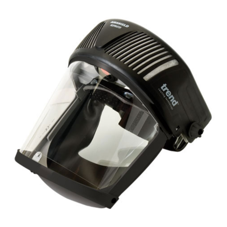
The Airshield is a lightweight Powered Respirator intended for protection against all solid dusts. This is combined with full eye and face protection from impact and chemical liquid splash.
The Airshield is powered by either one or two rechargeable battery packs inside the respirator. Air is filtered through the respirator to provide a constant flow of clean air over the face. A soft face seal ensures positive pressure is maintained within the visor and prevents debris or contaminated air entering the visor area. The visor is mounted on a fully adjustable headband providing a comfortable fit for most head sizes.
Typical use for the Airshield Respirator is the protection of individuals in Agriculture, Engineering, Pottery, Insulation, Woodworking, Dental Laboratories, Aerospace and other places where dust is present. All respirators must be used in atmospheres containing sufficient oxygen to support life (usually 17% to 23% by volume).
All parts, including filters and accessories are easily changed without the use of special tools and come packed for immediate use.
Read this manual before using the Airshield. It must be fitted and used in accordance with this manual to obtain the design performance. Use as part of your maintenance programme.
ACCESSORIES
| AIR/1 | THP2 filter packs (packed 3) |
| AIR/10 | THP2 filter packs (packed 1) |
| AIR/2 | Pre-filter (packed 3) |
| AIR/3C | Visor overlay - clear (packed 10) |
| AIR/3G | Visor overlay - green anti-glare (packed 10) |
| AIR/4 | 4 hour battery |
| AIR/5/UK | 230v charger (UK) |
| AIR/5/EURO | 220v charger (Euro) |
| AIR/5/ANZ | 230v charger (Australia & New Zealand) |
| AIR/WIPE | Visor wipes |
| AIR/WSP | Woodturners spare pack comprises: 1 x THP-2 filter, 3 x pre-filter, 10 x visor overlay & 1 x face seal (see catalogue) |

Not to be used if the contaminate is potentially explosive or highly flammable.
TECHNICAL SPECIFICATION
| Type: | Respirator, powered particle filtering device. |
Respiratory Approvals
| Europe: | Complies with European Standard BS EN146:1992 Class THP2. |
| UK: | Suitable for use under COSHH, CAW, CLAW and IRR. |
| Head Protection: | This is NOT an industrial safety helmet. |
Eye Protection Approvals
| Eye Protection: General | Complies to European Standard BS EN166:1995 Low energy impact |
| Weight: | Complete with battery pack and filters but no additional accessories, 735g nominal. |
| Head Size: | 52 to 62cm |
| Initial Design Flow Rate: | 180 l/min (clean filters, fully charged battery). |
| Min Design Flow Rate: | 140 l/min. |
| Duration: | One battery pack will operate in excess of 4 hours. Two battery packs will operate in excess of 8 hours. |
| Very High Work Rate: | EN 146 requires all manufacturers to state that at very high work rates, the pressure in powered respirators MAY become negative at peak inhalation. |
| Protection Factor: | Minimum 20 assessed against EN 146. |
Environmental Range:
| Storage | Use | |
| Temperature | 0°C to 45°C | -5°C to 50°C |
| Pressure | 800 to 1300 mbar | 800 to 1300 mbar |
| Humidity (out of direct sunlight) | 0 - 90% | 0 - 90% |
Abnormal Conditions
Not for use in explosive gas atmospheres. If the fan ceases to function whilst in the contaminated area, leave the contaminated area immediately, do not remove the Respirator until you are clear of the contaminated area. Note: During this condition there will be an increase in the exhaled carbon dioxide content within the respirator.
| Filter: | EN 146 Class THP2 tested against Sodium Chloride aerosol 0.02 to 2 micron with a mass median particle size of 0.6 micron. For use against solid and water based aerosols only. |
| Battery Pack: | 3.6v DC. Recharge time 14 hours from fully discharged or 1.5 hours per hour usage time. Life Nominal 900 cycles. |
| Battery Charger: | Mains operated double insulated complying with most high integrity standards. 4.35v DC output, constant current with current limiting circuit. No known overcharge problem when batteries are left in for long periods. |
| Visor: | EN 166 requires the visor to be stored in a clean dry area away from direct sunlight and heat, temp. 0-45°, atmospheric pressure 800-1300 mbar, humidity 0-90% |
ITEMS ENCLOSED
1 x Airshield complete
1 x Airflow Indicator
1 x 4 Hour Rechargeable Battery
1 x Disposable Visor Overlay - Clear (may be already fitted)
1 x Battery Charger
1 x Carry Bag
1 x COSHH Record Card (UK only)
1 x Instruction Manual
1 x Guarantee Card
DESCRIPTION OF PARTS

- Cover
- Pre-Filter
- Main Filter
- Battery Pack
- Face Seal
- Sweatband
- Headband
- Visor
- Disposable Visor Overlay (Clear)
- Fan/Motor Unit
- Charger
- Airflow Indicator
- Carry Bag
- Knob
- Switch
- Ratchet
SAFETY
General S afety
- Do not switch on the router with the cutter in contact with the workpiece.
- Clamp the workpiece securely to prevent it from moving during the routing operation.
- Always trail the cable away from the working area.
- Always remove the plug from the socket before making any adjustments to the machine.
- Check that the cutter is fitted securely. Be careful when handling cutters as they are sharp.
- Always keep the area around the workpiece and the floor clear of obstacles.
- The direction of routing must always be opposite to the cutter's direction of rotation.
- Do not feed the cutter into the workpiece until it is at full speed.
- Always guide the router with both hands.
- Never exceed the maximum speed specified for the cutter.
- When you are finished, allow the machine to come to a complete stop.
- Do not allow objects to dangle over the work area i.e. do not wear loose clothing such as a tie. Roll sleeves back and ensure long hair is tied back.
- Check before starting to cut that clamps will not obstruct the path of the router. When cutting through the full thickness of the material, ensure that the cutter cannot foul the vice, bench edge or other obstacles beneath the workpiece.
Airshield S afety Prec autions
- Control Of Substances Hazardous to Health (COSHH) recommend that Respiratory Protective Equipment should be stored in a cool dry place.
- For adequate protection the Airshield must fit or be adjusted to the size of the head.
- DO NOT clean with proprietary cleaning media or solvents, follow the instruction in manual.
- DO NOT apply paint, solvents, adhesives or self-adhesive labels which are not approved by Trend.
- DO NOT use Airshield without pre-filter and main filter fitted, with damaged seals and/or damaged visor.
- DO NOT use replacement parts except those supplied by Trend Machinery & Cutting Tools Ltd.
- To maintain the full efficiency of the Airshield, there must be no alteration to the structure or its component parts.
- When using two battery packs always fit two fully charged replacements.
- Toxic Dusts on the respirator or filters from usage should be handled in a safe manner in accordance with your chemical or material suppliers instructions. Used filters to be disposed of safely in the same manner.
If further information is required with regard to Airshield, please contact Trend Machinery & Cutting Tools Ltd.
BEFORE USE
 Charge the battery pack/packs before use.
Ensure the respirator is correctly assembled with pre-filter, main filter and either one or two fully charged battery packs fitted.
Battery Pack Charging

Battery pac k must be initially c harged for 24 hours.
The Powered Respirator is supplied with one rechargeable battery pack for four hours duration. For eight hours duration an additional rechargeable battery pack and battery charger is required.
Check that the voltage shown on the charger is suitable for the mains supply. A thermal fuse protects the charger against short circuiting and overloading.
Push the battery pack connector into the charger socket and plug the charger into the AC supply socket. The light on the charger confirms that the battery pack is charging.
Battery packs should be initially charged for 24 hours and 14 hours thereafter when fully discharged. A 3.5 hour charge will enable 1 hour of usage. Full working capacity of the battery will not be achieved until the battery has been through 3 or 4 complete charging cycles. Please note the light will not extinguish when a full charge has been achieved.
The charger must be disc onnec ted from the mains supply when not in use.
After the charging period, withdraw the charger from the AC supply socket and disconnect the battery pack from the charger.
ASSEMBLY & ADJUSTMENT
Battery Pack Removal and Replacement
Release the cover by lifting the left and right sides to disengage the lugs then pull forward and lift. The battery housings are located on either side of the main filter. Use two fully charged battery packs for eight hours duration or one battery pack for four hours duration. Plug a fully charged battery pack into the connector and push it down into the housing. Repeat for the opposite side if two battery packs are required. Lower the cover and push backwards to engage the lugs into the holes. Ensure the lugs are fully engaged in the holes.

Functional Test
The purpose of this test is to ensure that the airflow through the respirator is in excess of Airshield minimum design value of 140 litres per minute. Proceed as follows:
- Invert the Airshield and fit the air flow indicator over the fan-motor unit, ensure it is firmly pushed against the grommet.
- With the fan-motor unit running, hold the Airshield so that the air flow indicator tube is vertical and the holes around the base of the air flow indicator are not obstructed. The red ball must be at the top of the tube to ensure the minimum design flow rate is being exceeded.
If the flow rate is not sufficient, replace or charge battery pack/packs and/or change the main filter and re-test.
After completing the functional test, switch the Airshield off and remove the air flow indicator.


Fitting Procedure
Press and turn the ratchet knob anti-clockwise to enlarge the headband and lift the visor towards the back of the headband.
Fit the Airshield onto the head by entering the head into the headband.
Switch the fan-motor unit on and lower the visor over the face.

Press and turn the ratchet knob clockwise until a secure and comfortable fit is achieved. When removing, if necessary press and turn the ratchet knob anti-clockwise to loosen the headband.
Adjust the height of the visor as follows:
- Remove the Airshield.
- Press the stud through the hole on top half of headband.
- Slide the lower half to increase or decrease the height.
- Re-fasten headband by pushing the stud through the nearest hole and check the height of the visor when worn.
- Repeat above until a correct fit is achieved.
Ensure that the unit is pivoted down fully such that the headband stops are against the main fan housing.
The plastic headband lugs are designed to limit the movement of the visor to the face.
Adjusting the height will affect the fit around the chin.
Adjusting the face seal will affect the fit at the sides.
Ensure that the face seal around the chin and sides is pulled rearwards such that the seal deforms away from the frame and visor and not towards it.
Check the fit of the face seal in a mirror and/or run a finger around the line of the face seal to ensure contact.

At very high work rates, the pressure within the Airshield may momentarily bec ome negative at peak inhalation.
Vacate the c ontaminated area immediately if the airflow is reduc ed or stops.
If protective clothing is worn, ensure the bottom of the visor is not obstructed.
Removal Procedure
Vacate from c ontaminated area before removing the Airshield.
- Raise the visor and switch the fan-motor unit off.
- Lift the Airshield from the head.
- After finishing using the Airshield follow the maintenance procedures.
OPERATION
The switch (A) operates the fan-motor unit (B), powered by rechargeable battery pack(s) (C), which draws air (D) through the pre-filter (E) to remove larger particles of dust before being drawn through the main filter (F). The filtered air (G) is passed down over the face. Exhaled breath (H) leaves the respirator through holes in the bottom of the visor frame.

MAINTENANCE AND CARE
After using the Airshield follow the procedure below:
Airshield should not be c leaned with c ompressed air, solvents, sterilising by heat or autoclaving, as this will cause damage.
Precautions are to be taken to prevent inhalation of harmful dust or contaminant on the surface or retained on the filters.
- Carefully remove bulk contamination from the Airshield and wipe down with a damp cloth containing a mild detergent solution.
- Clean and sterilise all Airshield parts by wiping down the visor, face seal and headband with visor wipes (ref. AIR/WIPE) (Sodium Hypochlorite or Ethylene Oxide Gas have also been proved effective).
Gamma sterilisation is effec tive but causes embrittlement of plastic c omponents and is not rec ommended.
- Release the cover by lifting the left and right lower sides to disengage the lugs then pull forward and lift.
- Remove the pre-filter and main filter as described. Dispose of in accordance with local health and safety regulations.
- Remove battery pack(s). Ensure battery pack is clean and recharge.
- Wipe down with a damp cloth containing a mild detergent solution to remove any loose dust from inside the cover. Do not apply pressure to the fan blades, to clean use a soft
- Operate the switch to check the function of the fan-motor unit.
- Carry out the functional test.
Replace if deficient after the following checks:
- Excessive abrasion and scratches on the visor.
- The face seal for its seal to the visor and for holes.
- Fit and fastenings to the headband.
Scratched or damaged oc ulars (visor) may not offer full protec tion and therefore should be replaced.
Specific instructions for cleaning and disinfection of visor
Clean regularly with a damp cloth - do not use hydrocarbons, chemicals, cleaning fluids or solvents on the visor. If necessary, a mild solution of washing-up liquid and warm water may be used.
Routine Checks
The expected life of the visor is approximately 3 years if well maintained and cleaned. (Care must be taken not to scratch the visor).
This manual contains relevant guidance on routine maintenance, however, you may wish to introduce additional checks as required by COSHH. The following table shows the frequency of these checks.
| Operation | Frequency |
| Clean Internally and Externally | Daily |
| Visual Inspection | Daily |
| Charge Battery Pack/Packs | Daily |
| Functional Test* | Daily, Weekly and Monthly |
* Remarks: Dust from wood, grain and cement may suit more frequent replacement of pre-filter to extend the life of the main filter. No filter should be left in the hood/helmet for more than 1 month if in daily use or 3 months if used infrequently.
Monthly - All items checked and signed by Operator.
Quarterly - All items checked and signed by Supervisor.
| Symptom | Cause | Remedy |
Reduced airflow | Cover air holes Clear air blocked | holes |
| Pre-filter clogged | Fit a new pre-filter | |
| Main filter clogged | Fit a new main filter | |
| Battery flat | Fit a recharged battery pack(s) | |
No airflow Airshield | switched OFF | Press switch to ON |
| Switch faulty | Return to manufacturer | |
| Battery pack not fitted | Fit a fully charged battery pack | |
| Battery pack connection | Push fully home | |
| Battery pack discharged | Fit a fully charged battery pack | |
| Fan-motor unit failure | Fit replacement fan-motor unit |
STORAGE
The Airshield should be placed in the carry bag, stored within a temperature range of 0°C to 45°C and out of direct sunlight. Replacement filters are to be left in their sealed bags and expiry dates to be checked regularly.
TRANSPORTATION
The complete respirator should be transported in the carry bag provided. Good quality commercial packing should be used.
REPLACEMENT OF SPARE PARTS
Replacement parts and accessories supplied by Trend Machinery & Cutting Tools Ltd. should only be used. The use of accessories not supplied by Trend Machinery & Cutting Tools Ltd. will not be guaranteed and invalidate such National approvals as held by Trend Machinery & Cutting Tools Ltd. Modifications to the Airshield will make the approvals invalid and the use illegal under National Laws and Guidance.
Trend Machinery & Cutting Tools Ltd.
replacement parts and accessories, must only be used with the Trend Airshield.
Battery Pack
- Release the cover by lifting the left and right lower sides to disengage the lugs then pull forward and lift.
- Insert finger into housing cut-out, lift battery pack and unplug from connector.
- Plug a fully charged battery pack into the connector. Push the battery pack down into the housing.
- If two battery packs are fitted repeat for opposite side. Lower the cover and push backwards to engage the lugs into the holes. Ensure the lugs are fully engaged in the holes. Carry out a functional test.
Pre- Filter

- Release the cover by lifting the left and right lower sides to disengage the lugs then pull forward and lift.
![]()
Precautions are to be taken to prevent inhalation of harmful dust or contaminant retained on the pre-filter and inside the cover.
- Pull pre-filter away from inside the cover and dispose of in accordance with local health and safety regulations. Never re-use a pre-filter.
- Wipe down with a damp cloth to remove any loose dust from inside the cover.
- Attach the coarse side of the replacement pre-filter onto the hook fastener strips inside the cover. Lower the cover and push backwards to engage the lugs into the holes. Ensure the lugs are fully engaged in the holes. Carry out a functional test.
Main Filter
- Release the cover by lifting the left and right lower sides to disengage the lugs then pull forward and lift.
![]()
Precautions are to be taken to prevent inhalation of harmful dust or contaminant retained on the main filter and inside the cover. - Pull the corners of the main filter to release the four press studs from the housing.
- Dispose of in accordance with local health and safety regulations. Never re-use a main filter.
- Wipe down with a damp cloth to remove any loose dust from inside the cover and housing.
- Fit a new main filter by attaching the two press studs onto the housing. Support the housing and press along the main filter edges, attach the other end onto the two press studs. Ensure the filter seal is fully seated on the housing. Lower the cover and push backwards to engage the lugs into the holes. Ensure the lugs are fully engaged in the holes. Carry out a functional test as described previously.
Face Seal

- Pull the face seal away from the hook fastener strip on visor frame.
- Establish the centre of the replacement face seal and attach the brushed nylon side onto the hook fastener strip on the bottom of the visor frame. Continue attaching the face seal to the visor frame and ensure no gaps are on the end of the face seal and visor frame.
- Adjust the position of the face seal to achieve close contact around the face.
The knob assembly for the headband is adjusted to relieve pressure to the temples.
Sweatband

- Pull apart to separate hook fasteners and remove the sweatband from the headband. Replacement of the sweatband is the reverse of the above procedure. Ensure the foam surface is fitted against the headband and the slits are fully fitted over the headband.
Headband

- Pull apart to separate hook fasteners to remove the sweatband from the headband.
- Detach each end of the face seal from the headband.
- Unscrew and remove the knob (4). Push the pivot pin (1) out through the cover washer (3), torque washer (2) and headband. Repeat for the opposite side to release the headband and remove the torque washers (2).
- Replacement of the headband is the reverse of the above procedure. Ensure the torque washers (2) are assembled onto the headband correctly.
Visor Overlay
- Peel away visor protector and ensure visor surface is clean.
- Peel backing paper from adhesive strips on replacement visor protector. Position centrally onto visor surface, press down adhesive strips and remove protective paper.
Fan-Motor Unit

- Remove the main filter and battery pack/packs.
- Disconnect fan-motor unit plug from socket (flip-up locking pin on connector male and pull apart socket). Withdraw the fan-motor unit from retaining grommet.
- Replacement of the fan-motor unit is the reverse. Of the above procedure (note fan orientation). Fitting will be made easier with the visor removed and with the use of a water based lubricant such as liquid soap. Apply a small amount of lubricant around the inside of the retaining grommet before insertion of the fan. Carry out a functional test.
![]()
Hold the fan by the sides only, do not push or apply any pressure to the fan blades.
Visor

- Disengage tab from centre of visor and lower the flap. Carefully press the sides of the visor and lift it from the visor frame.
- Flex replacement visor and insert the top and sides into the visor frame ensuring that the top visor tabs slide outside of the frame. Swing the bottom of the visor into place, lift the flap and engage the latch through the visor centre hole.
AIRSHIELD SPARE PARTS DIAGRAM

AIRSHIELD - SPARE PARTS LIST
| Item | Qty | Description | Ref. |
| 1 | 1 | Fan/Motor | WP-AIR/01 |
| 2 | 1 | Airflow Indicator | WP-AIR/02 |
| 3 | 1 | Face Seal | WP-AIR/03 |
| 4 | 1 | Headband | WP-AIR/04 |
| 5 | 1 | Sweatband | WP-AIR/05 |
| 6 | 1 | Carry Bag | WP-AIR/06 |
| 7 | 1 | Visor | WP-AIR/07 |
| 8 | 1 | Cover | WP-AIR/08 |
| 9 | 1 | Rear Comfort Pad | WP-AIR/09 |
| 10 | - | ||
| 11 | 2 | Pivot Pin | WP-AIR/11 |
| 12 | 2 | Cover Washer | WP-AIR/12 |
| 13 | 2 | Torque Washer | WP-AIR/13 |
| 14 | 2 | Knob | WP-AIR/14 |
| 15 | - | ||
| 16 | 1 | Charger 230v UK - PLP1100 | AIR/5/UK |
| 1 | Charger 220v Euro - PLP1110 | AIR/5/EURO | |
| 1 | Charger 230v Australia/New Zealand - PLP 1130 | AIR/5/ANZ | |
| 17 | 1 | Battery 4 Hour - 3.6 volt DC | AIR/4 |
| 18 | 0 | Visor Overlay - Clear (pack of 10) | AIR/3C |
| 19 | 0 | THP2 Filter (pack of 3) | AIR/1 |
| 20 | 0 | Pre-Filter (pack of 3) | AIR/2 |
| 21 | 1 | COSHH Record Card | LEAF/AIR/CRC |
| 22 | 1 | Manual | MANU/AIR |
Trend Machinery & Cutting Tools Ltd.
Odhams Trading Estate St Albans Road
Watford WD24 7TR England
Enquiries: 0800 487363
Technical Support: 0044 (0) 1923 224681
Fax: 0044 (0) 1923 236879
Email: mailserver@trendm.co.uk
WWW: www.trendmachinery.co.uk
Documents / ResourcesDownload manual
Here you can download full pdf version of manual, it may contain additional safety instructions, warranty information, FCC rules, etc.
Advertisement


Need help?
Do you have a question about the AIRSHIELD and is the answer not in the manual?
Questions and answers