Boston Whaler 170 Montauk Manual
- Owner's manual (103 pages) ,
- Owner's manual (36 pages) ,
- Owner's manual (82 pages)
Advertisement
- 1 Your Product
- 2 General Arrangement & Specifications
- 3 Fuel System
- 4 Electrical System
- 5 Bilge Pump
- 6 Propulsion System
- 7 Getting to know your Product
- 8 Anchoring Information
- 9 Documents / Resources
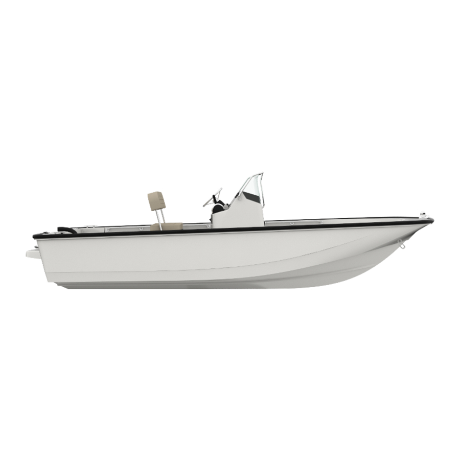
Your Product
Construction Standards
"THE MISSION OF BOSTON WHALER IS TO PROVIDE CONSUMERS WITH THE SAFEST, HIGHEST QUALITY, MOST DURABLE BOATS IN THE WORLD".
We are dedicated to creating a superior product providing you with comfort, performance, safety and dependability. All of our boats comply with the safety standards set by the United States Coast Guard and are designed, engineered and manufactured in accordance with applicable recommendations and guidelines of the American Boat and Yacht Council (A.B.Y.C.) and certified by the National Marine Manufacturers Association (N.M.M.A.).
Our Hull

- No air voids
- High density closed cell non-absorbent foam
- High quality resins and gelcoats
- Woven glass matting
Boston Whaler hulls are constructed with our patented Unibond construction. This involves shooting high density foam into a closed mold system. The foam expands to fill voids in the hull, and when the finished product is pulled from the mold, the deck and the hull are chemically bonded to form a solid, inseparable unit.
Servicing your Product
When your 170 Montauk needs to be serviced or regular maintenance is needed, it should be taken to an authorized Boston Whaler dealer.
To find a Boston Whaler dealer in your area call:
1-800-942-5379
Domestic/International
If a problem is not handled to your satisfaction:
Discuss any warranty related problems directly with the service manager of the dealership or your sales person. Give the dealership an opportunity to help the service department resolve the matter for you.
Hull Identification Number
The "Hull Identification Number" is located on the starboard side of the transom wall.
This is the most important identifying factor and must be included in all correspondence related to your vessel. Failure to do so will only create delays. Also of vital importance are the engine serial numbers and part numbers when writing about or ordering parts for your engine.


High performance boats require intimate knowledge of their handling characteristics for safe high speed operation.
- Learn the effects of trim, steering and throttle changes at gradually increasing levels of speed.
- Approach full throttle while adjusting trim for safe handling of the vessel.
General Arrangement & Specifications
Specifications & Dimensions

The canvas shown here is for reference only.
| Overall Length | 17'0" | 5.18 | m |
| Trailerable Length | 20'2" | 6.15 | m |
| Bridge Clearance | 6'11" | 2.10 | m |
| Bridge Clearance (no top) | 4'7" | 1.39 | m |
| Beam | 6'10" | 2.08 | m |
| Draft, (Hull Only) | 9" | .23 | m |
| Weight (dry, no engine) | 1400 lbs. | 635 | kg |
| Swamped Capacity | 3400 lbs. | 1542 | kg |
| Maximum Engine Weight | 410 lbs. | 185 | kg |
| Maximum Weight, (passengers, engine(s), gear),** | 1650 lbs | 748 | kg |
| Persons | 7 | ||
| Maximum Horsepower | 90HP | 67 | kw |
| Minimum Horsepower | 60 HP | 44 | kw |
| Fuel Capacity(portable) | 13.2 gal.(U.S.) | 50 | L |
| * Waterline *** Engine Draft,(See Notice) | |||
 NOTICE
Specified measurements are approximations and are subject to variance.
NOTICE **
Exceeding this weight will affect the bost's performance. DO NOT Exceed the weights listed on the capacity plate.
NOTICE ***
Optional equipment and loading of the boat will affect the draft measurements. Follow the recommendations listed on your capacity plate regarding the maximum amount of weight the boat can safely carry.
Standard Features


- Bow Chock/Navigation Light
- 8" Cleat, Stainless Steel
- Heavy Duty Rubrail
- Stainless Steel Bow Rail
- Foward Lifting Eye
- Anchor Locker
- Console Grab rail, Stainless Steel
- Acrylic Windshield
- Navigation Light Base
- Instrument Panel
- Console Access Door w/ Storage Bin
- Stainless Steel Steering Wheel
- Gear Shift/Throttle Control
- Console Cupholders, (2)
- Reversible Pilot Seat Backrest
- Reversible Pilot Seat Cushion
- Reversible Pilot Seat Base
- 2-6.6 Gal. (49.96L) Fuel Tanks, (Portable)
- Galvenized trailer
- Motorwell Drain, (2)
- Stern Lifting Eye, Port/Starboard
- 90 ELPT EFI 4-stroke Mercury engine
- Access Plate
- Sump Cover/Bilge Pump Access
- Stainless Steel Side Rail
- Electric Horn
Optional Features

- Blue graphics, striping and logos
- Telescoping ladder and swim platform
- 60 ELPT EFI Bigfoot 4-stroke Mercury engine
- 100 ELPT EFI 4-stroke Mercury engine*
- Bow cushion
- 72 Qt. (68.1L) Cooler seat w/ cushion and backrest
- Sirius Satellite Radio Antenna
- Navman 4350 Fishfinder
- Navman 7100 VHF Radio
- MP3 Player Receptacle
* CE Option
** Also part of the Fishing Package

Fishing Package
- Compass
- 72 Qt. (68.1L) Cooler seat w/ cushion backrest and 4 rodholders
- Tackle drawers

Canvas
- Canvas sun-top (Red or Blue) with stainless steel fittings and boot.
- Forward Support Pole 2
- Aft Support Strap
- Main Support Pole
- Center Support Pole
- Forward Support Pole 1
- Sun-top Slide Track Base
Standard & Optional Seating Arrangements

STANDARD
- Reversible Pilot Seat w/ Locking Backrest
OPTIONAL
- 72 Qt. (68.1L) Cooler Seat w/ Backrest*
- Bow Cushion
*Backrest with 4 rodholders not shown
NOTICE
The deck drain provides self-bailing capabilities while the boat is static in the water and no passengers on board. This feature prevents the accumulation of water in the cockpit. the drain must be in place when underway.
NOTICE
Depending on the type of boat you have, you may have underwater fittings that need drain plugs. Garboard drain plugs and fishbox drain plugs need to be in place before the boat goes into the water. Any fitting that will be underwater needs to be plugged or the seacock needs to be closed
NOTICE
An inspection of the through hull fittings is recommended. Through hull fittings should be checked for proper seal annually and repaired as required. When the boat is in the water the underwater fittings can be checked for dripping. It is recommended that the underwater fittings be removed, cleaned and resealed every other year.
NOTICE
If the through hull fittings need to be replaced, it is recommended that an authorized Boston Whaler dealer perform this type of repair. Through hull fittings that are improperly installed can cause premature hull failure and may void the Boston Whaler limited warranty.
Through Hull Locations


- Anchor Locker Drain
- Bilge Sump Drain
- Bilge Pump Outlet
- Motorwell Drain, (2)
Label Location

| Replacement Part No. | ||
| 1811368 | |
| 1795087 | |
| 1811367 | |
| 1735926 | |
| ||
NOTICE
It is important to replace any damaged or unreadable label. Call your Boston Whaler dealer for replacement labels.
Deck Occupancy Plan

Accommodation deck:
This area of the boat is inside the cockpit and includes helm seating. Movement in this area should be done with extreme caution while the boat is underway. A sudden shift in boat direction can cause a loss of balance and lead to injury or death.

Working deck:
This area is intended for occupation ONLY while mooring, anchoring, loading/unloading or when the boat is at rest. NEVER operate the engine while loading or unloading swimmers/divers from the swim platform/ladder.


Be aware of your footing while the boat is underway, slipping or falling could result in serious injury or death, especially if the boat is in motion or in rough seas. Keep the accommodation deck clean, so if movement is neccessary it will be free of obstruction.
Gelcoat surfaces are slippery when wet. Use extreme caution when walking on wet surfaces. Use care when waxing to ensure that walkways are not made dangerously slippery.
Never occupy the working decks while the boat is underway. ONLY sit in areas that are designated for sitting. NEVER sit on the gunwales while the boat is moving.
Trolling Motor Reinforcment Location
The 170 Montauk has reinforced areas of the bow that will make it easier to mount a trolling motor. The reinforced sections are located on either side of the bow navigation lights and extend back along the gunwale. The phenolic material can be drilled and tapped to hold machine screws. In some instances the trolling motor will not be compatible with the optional bow rail. See your Boston Whaler dealer regarding this. The exact location of the phenolic can be found in the "REINF. LOCATION DIAGRAM" in your owner's manual packet. Please refer to this document before drilling into the deck of your boat.

Distance from the deck to waterline, (for determining the correct shaft length of the trolling motor.)

Trolling Motor,
(Reference ONLY)
Fuel System
Check for leaks in tubing, connections and hoses. Correct the cause of the leaks and ventilate the area to insure that no fumes remain, prior to energizing any electrical equipment and/or starting the engines.
Static electricity can ignite gasoline vapors causing serious injury/death and/or destruction of property.

Use of improper gasolines can damage your engine seriously. Engine damage resulting from use of improper gasoline is considered misuse of engine and will void the warranty. Follow engine manufacturer's recommendations regarding the types of fuel and oil to use.

Leaking fuel is a fire and explosion hazard, inspect the system regularly. Examine fuel tanks and exposed lines for leaks and corrosion.
Oil and fuel spills can be dangerous and can subject offenders to severe penalties
NOTICE
Remove portable tanks from boat and fill from shore. When fueling is complete, secure tanks to deck with straps provided.
NOTICE
Fuel tanks should never be filled to capacity, allow 2% for expansion.
The 170 Montauk has provisions for a gasoline fuel system. There is a section under the reversible pilot seat that will hold a pair of 6.6 Gal.(25 L) removable fuel tanks. Straps are used to secure the tanks to the deck. There is a rigging tube under the deck for running the fuel line to the engine. It is recommended that you follow all instructions regarding the filling and transporting of the removable fuel tanks.
Please take time to read and understand all the fuel related information and warnings in the engine owner's packet.

170 Montauk Fuel System
- 6.6 Gal, (25L) portable fuel tank,(2)
- Fuel tank strap
- Primer bulb
- Rigging tube, (in hull)
- Fuel line from tank(s)
- Fuel line tank connection port
- Fuel tank level gauge
- Fuel tank vent
- Fuel tank fill
Static Electricity and the Fuel System
There is a danger that static electricity can ignite gasoline vapors that have not been ventilated outside an enclosed area. Use extreme caution when fueling your boat from a source outside the regular venues, (e.g. marinas, fuel service stations.)
Your boat has safety features that can be circumvented by not adhering to standard fueling practices. Your boats bonding system protects it from creating and discharging static electricity.
Your boat must be in contact with the water or a land based grounding system. Here are some helpful suggestions to keep you safe from static electricity while refueling your boat.
- NEVER fuel your boat in unsafe conditions such as: suspended on a sling or in a situation that increases the likelihood of static discharge.
- NEVER use homemade containers to fill your fuel tanks.
- Fuel carried on-board outside of a fixed fuel system should be stored in an approved container or in a portable tank such as provided for outboard engines and be stowed safely outside of the engine or living compartment(s).
- Shut down the engine(s), motors and fans prior to taking on fuel. Any ignition sources should be extinguished before filling the fuel tank(s).
- Close all ports, windows, doors and hatches.
- Fueling should never be done at night except in well-lighted areas.
- Always keep the fuel nozzle in contact with the fuel fill plate or the edge of the fuel tank opening throughout the filling process.
- Allow areas where gasoline vapors could collect to be ventilated before starting the engine(s).
- Wipe any spillage completely and dispose of rags or waste on shore.
- Secure the fill cap tightly.
- Portable tanks should only be filled while on the ground; never on-board the boat.
REFER TO THE "Do's and Don'ts At The Gas Pump" DVD IN YOUR OWNER'S MANUAL PACKET FOR more information.
Ethanol-Blended Fuel
Ethanol is an oxygenated hydrocarbon compound that has a high octane rating and therefore is useful in increasing the octane level of unleaded gasoline.
NOTICE
The use of improper gasoline or additives can damage your fuel system and is considered misuse of the system. Damaged caused by improper gasoline or additives WILL NOT be covered under warranty.
The fuel-system components of your Mercury engine(s) have been tested to perform with the maximum level of ethanol-blended gasoline (10% ethanol) currently allowed by the EPA in the United States.
Special precautions should be considered with the use of fuel containing ethanol in your system. Fuels with ethanol can attack some fuel-system components, such as tanks and lines, if they are not made from acceptable ethanol-compatible materials. This can lead to operational problems or safety issues such as clogged filters, leaks or engine damage.
Your boat was manufactured, and shipped from the factory, with ethanol-compatible materials. Before introducing gasoline with ethanol into your fuel tank, ask your dealer if any components have been added or replaced that are not recommended by Boston Whaler, Mercury or may not be ethanol-compatible.
FILLING THE TANK
It is best to maintain a full tank of fuel when the engine is not in use. This will reduce air flow in and out of the tank due to changes in temperature as well as limiting exposure of the ethanol in the fuel to humidity and condensation.
PHASE SEPARATION
Humidity and condensation create water in your fuel tank which can adversly effect the ethanol blended fuel. A condition called phase separation can occur if water is drawn into the fuel beyond the saturation point. The presence of water in the fuel beyond the saturation level will cause most of the ethanol in the fuel to separate from the bulk fuel and drop to the bottom of the tank, significantly reducing the level of ethanol in the fuel mixture in the upper level (phase). If the lower level (phase), consisting of water and ethanol, is deep enough to reach the fuel inlet, it could be pumped directly to the engine(s) and cause significant problems. Engine problems can also result from the reduced ethanol/fuel mixture left in the upper phase of the tank.

- Condensation
- Upper Phase (water+fuel+ethanol)
- Lower Phase (water+ethanol)
- Fuel Inlet to Engine
The use of fuels containing ethanol higher than 10 percent (E-10) can damage your engine and/ or fuel system and will void the warranty.
E85 FUELS COULD SERIOUSLY DAMAGE YOUR ENGINES AND MUST NEVER BE USED.
ADDITIVES
There is no practical additive known that can prevent or correct phase separation. The only solution is to keep water from accumulating in the tank. If phase separation does occur, your only remedy is to drain the fuel, clean and dry the tank completely and refill with a fresh, dry load of fuel.
FUEL FILTERS
Mercury already provides the appropriate level of filtration to protect the engine from debris. The addition of another in-line filter to the system will create a possible flow restriction that can starve the engine(s) of fuel.
As a precaution, it is advisable to carry extra on-engine filters in case filter plugging from debris in the fuel tank becomes a problem during boating.
MAINTENANCE
Periodically inspect for the presence of water in the fuel tank. If any is found, all water must be removed and the tank completely dried before refilling the tank with any fuel containing ethanol.
STORAGE
Long periods of storage and/or non-use, common to boats, create unique problems. When preparing to store a boat for extended periods, of two months or more, it is best to completely remove all fuel from the tank. If it is not possible to remove the fuel, maintaining a full tank of fuel with a fuel stabilizer added to provide fuel stability and corrosion protection is recommended.
Electrical System
Batteries contain sulfuric acid which is dangerous and can cause serious injury. AVOID contact with skin, eyes and clothing. If contact occurs, immediately flush the affected area with large quantities of water and call for medical assistance
- Never use an open flame in the battery storage area.
- Avoid striking sparks near the battery
- A battery will explode if a flame or spark ignites the free hydrogen given off during charging.
- The battery should always be disconnected before doing any work or maintenance on the electrical system.
Never reset a breaker without first determining and correcting the cause of the trip. Should a circuit repeatedly trip, have a qualified electrician determine and correct the cause.
If equipped with a battery switch, you will need to stop the engine before moving the switch to the "OFF" position.
NOTICE
Always store the battery in the the battery box. Use the straps and clamp to keep the box secure while underway.
Battery Information
Your 170 Montauk is equipped with an electrical system that provides power for the following:
- Engine ignition
- Engine tilt trim system
- Helm switch panel & helm instrument panel
- Lighting/Navigation system
- Livewell system, (optional)
- Add-on accessories and electronics
The battery box is located inside the console on the starboard side. Your battery should always be enclosed in the battery box provided with your boat. The box will contain any spilled acid, as well as protect the battery terminals from damage or inadvertant shorting from contact with metal objects.
The battery box should always be secured in place by using the straps and clamps provided, the straps will ensure that while underway the battery will not move around, causing damage to components stored in the same area.
Battery Maintenance
The most life shortening experience for the battery is to be drained to zero charge before recharging. When a battery discharges, the active material on both positive and negative plates converts to lead sulfate, causing the plates to become more alike in an electrical charge. The electricity conducting battery acid becomes weaker and the voltage drops. As the battery remains discharged, the process continues until recharging the battery becomes impossible. If the battery does become run down be sure to recharge it as soon as possible. Over charging the battery can be just as detrimental to its life as running it down too far. Battery maintenance should include:
- Inspect the battery and charging system be fore each use for loose connections or wiring.
- Coat the terminals with dielectric grease.
- Keep the battery safe and dry.
- Remove the battery from the boat during cold weather or long term storage.
Battery Switch
(optional)
The 170 Montauk has the option of using a battery switch. The switch; located on the aft wall of the console interior, allows you to control the delivery of DC power from the battery to the engine as well as allowing the alternator to charge the battery. Your battery selector switch has two settings, "ON" and "OFF", "ON" gives you power from the battery only. "OFF" you have no power to the engine. Remember to turn the battery selector switch to "ON" before you attempt to start your engine.
Note: The bilge pump cannot be turned off with the battery selector switch.

Ignition Shutdown Switch
Wear your lanyard at all times while operating the boat. It is for emergency stopping only. Do not use it to shut off the engine during normal operation. The lanyard should be long enough to prevent inadvertent activation.
The 170 Montauk is equipped with an ignition shutdown safety switch. It is located starboard of the steering wheel, below the ignition switch. The ignition shut down safety switch incorporates a shut-off switch, switch clip, lanyard and lanyard clip, which is clipped to the operator. If an emergency arises where the engine must be shut down, a pull on the cord to release the clip from the shut-off will shut down the engine. This switch is designed to shut the engine off when the operator of the boat leaves the control station, either accidentally by falling into the boat, or by being ejected overboard. This would most likely occur as a result of poor operating practices.

Electrical Diagram
This owner's manual supplement contains diagrams for your boat. These electrical diagrams were generated by technicians in our engineering department and are for reference and use by service technicians. Boston Whaler does not recommend that you attempt to work on the electrical system yourself, instead we suggest that you take it to an authorized Boston Whaler dealer for electrical service. Boston Whaler reserves the right to change or update the electrical system on any model at any time without notice to the consumer and is not obligated to make any updates to units built prior to the changes.

Instrument Panel

- Instrument Panel
- Tachometer (0-7000 RPM)
- Voltage Gauge (0-40 Volts)
- Water Pressure Gauge
- 12V Receptacle
- 10 Amp 12V Receptacle Plug Breaker
- Accessory Switch
- 10 Amp Accessory Switch Breaker
- Stereo Switch
- 5 amp Stereo Switch Breaker
- Bilge Pump Switch, 3 Position
- 5 Amp Navigation/Anchor Switch Breaker
- Navigation/Anchor Switch
- 5 Amp Horn switch Breaker
- Horn switch
Never reset a breaker without first determining and correcting the cause of the trip. Should a circuit repeatedly trip, have a qualified electrician determine and correct the cause.
12 Volt Accessory Receptacle
NOTICE
DO NOT insert a cigarette lighter into this receptacle. Damage to the unit & system could occur.
Your 170 Montauk is equipped with a 12 volt accessory receptacle located on the instrument panel. It is a DC (cigarette lighter) style receptacle to be used with any 12 volt accessories using this type of plug. The receptacle is made of corrosion resistant marine grade materials and has a moisture proof cap. There is a 10 amp breaker button located just below the receptacle. Be sure to use accessories that do not exceed the rated capacity of the circuit, (10 amps) or the breaker will trip.
Navigation Lighting
NOTICE
The improper sequence of navigation lighting may be as dangerous as not having lights at all.
NOTICE
When using the SUN-TOP, make certain that all securing straps are taut. Damage to the navigation light can happen if the canvas frame straps are loose or not secured properly.
Navigation lighting is provided as part of the 170 Montauk's electrical system. Navigation lights must be displayed while underway, from sunset to sunrise. The term "underway" means not at anchor or docked. While at anchor in open water it is required that your 360° pole light be illuminated. It is the boat owners responsibility to display the proper sequence of navigation lighting. Do not change the sequence of navigation lighting of your boat. It is also the responsibility of the boat owner to ensure that the navigation lights are in good working order. The navigation lights will let other boaters see the direction your craft is traveling and its approximate length. When operating in reduced visibility or at night it is only prudent to slow the boats speed and keep a "proper lookout". It is important that you understand navigation lights and their usage for your safety and the safety of others. The navigation lights are controlled by pressing the NAV/ANC switch located on the instrument panel. When using the canvas suntop with the console mounted navigation light be sure to slide the navigation light through the opening in the top of the sun-top. Be sure to remove the light pole from the base before stowing the canvas Suntop. When not being used, the aft pole light can be stowed in clips located on the starboard aft cockpit area.

Bilge Pump
NOTICE
The bilge pump is wired directly to the battery. The bilge pump switch can be set in several positions for bilge pump operation. Be sure the bilge pump float switch is clear of debris to prevent continuous operation and subsequent discharge of the battery.

- 1100 GPH bilge pump
- Float switch
- 1-1/8" Bilge pump discharge hose
- Bilge sump
- Bilge sump plug
- Bilge pump outlet
- Bilge sump cover
The 170 Montauk is equipped with an 1100 GPH electric bilge pump. It is located in the aft cockpit sump just forward of the motorwell. The switch for bilge pump operation is located on the instrument panel.

Operation
The bilge pump switch has three operating positions:

- Position 1-OFF-This position disconnects the power from the battery. When moored the sump drain plug can be removed to allow any standing water to be drained overboard. It is normal for some water to enter the sump.
- Position 2-AUTO-This position energizes the float switch. The float switch cycles the bilge pump "ON" when the water level in the sump reaches a pre-determined level. If the boat is under load and left unattended while the sump drain plug is not in place, the battery can be discharged, (due to continuous cycling). This switch position should be used when the boat will be supervised.
- Position 3-ON-This position is for manual bilge pump operation. The pump will run contiuously until the switch is returned to one of the previous positions.
Maintenance
The bilge pump and float switch units are completely sealed and little maintenance is required. It is important to keep the bilge pump in good working order, check around the float switch for debris and gummy bilge oil that could impede the bilge pump from working properly. Check the bilge pump and hoses for wear; clean and repair if neccessary.
Note: The bilge pump is wired directly to the battery. If the boat is to be dry docked for an extended amount of time be sure to disconnect the battery cables.
Propulsion System
Propeller Information
Disconnect power by moving the battery switch to the "OFF" position prior to removing the propeller.
NOTICE
It is advised that you always carry a spare propeller, propeller hardware and propeller wrench on board. Should your propeller become damaged it can be easily replaced.
NOTICE
Under no circumstance use a propeller which allows the engine to operate at a higher than recommended RPM.
The engine on the 170 Montauk has been equipped with a propeller; which our tests have shown to be best suited for general use under normal conditions and load. In some situations you may wish to change the propellers to give your boat slightly different performance characteristics. Changing your boats running surface, such as the addition of bottom paint will affect the type and size of propeller required.
In general, changing to a lower pitch propeller will increase acceleration and load pulling capability, with a slight decrease in top end speed. If you choose to change propellers, the type should be discussed with your Boston Whaler dealer.
All propellers are designed to provide maximum forward thrust, so the reverse thrust of the propeller will not be as efficient.

- Propeller Diameter
- 1 Revolution, (Pitch)
- Propeller Rake

Propeller Assembly
Gear Shift & Throttle Control
Shift only when engine is running. Pause in neutral while shifting, wait for boat to lose headway, and then shift quickly. Easing into gear can damage the engine.
The 170 Montauk is equipped with a gear shift/throttle control unit mounted on the console directly starboard of the steering wheel. The gear shift/throttle control unit for the engine activates both shifting mechanism and throttle. The control must be in the "NEUTRAL" position to start your engine. Neutral is the most upright position of the control unit and acts as an idle, the propeller is not rotating. There is a "throttle only" button at the center of the throttle control that when depressed will disengage the shifting mechanism and will allow you to operate the throttle without engaging the propeller. This button will automatically engage the shifting mechanism once the throttle control has been moved back to its center position (you will hear and feel a click when it is engaged). Moving the lever forward engages the forward gear and then the throttle advance.
To reverse power, bring the control lever back to engage the reverse gear and increase the reverse thrust. The throttle control regulates the RPM of the engine. Regulating the RPM of the engine will control the speed of the boat. Pulling back on the gear shift/ throttle control while moving at a high speed will cause a sudden slowing of the boat and will create a following wake which may rise above the transom and flood the boat. Understanding your boat and its reactions at speed will make boating for you safer and more enjoyable.

Power Trim Operation
The power trim & tilt system allows you to raise and lower the engine outdrive for trailering, launching and beaching. This also allows for ideal boat angle (in relation to the water surface) for a given load and water condition. In most cases, best all-round performance is obtained with the engine adjusted so that the boat will run at a 3° to 5° angle to the water. The power trim is located on the inboard side of the gear shift/throttle lever handle.
NOTE: Boats can be operated in a manner and at certain speeds resulting in trim angles that could cause visibility to be obscured. Motor trim, hull trim plane angles (if equipped), boat load distribution and speed are factors that affect a boat's trim angle.

Steering Information
Do not cover cracks in the steering cable or fittings with tape or other sealants. This will create a hazard in which the cable can fail without warning.
Your 170 Montauk is equipped with a teleflex no-feedback steering system. The Teleflex no-feedback steering system has a clutch mechanism which prevents the engine torque from being felt at the steering wheel. This reduces driver fatigue by eliminating the constant need to fight the wheel.

Maintenance
The mechanical steering system should be checked periodically by your Boston Whaler dealer for proper lubrication, alignment and to make sure there is no looseness or binding of the cable. Proper maintenance of this system will ensure worry-free usage for the life of your boat.
No-feedback steering system maintenance should include the following:
- After the first few hours of operation and at regular intervals, check all fasteners and the complete steering system for security and integrity.
- Check all moving parts to be sure they are free of salt build-up and other foreign material. Such build-up will affect their operation.
Steering Pull
Steering pull is unnecessary and unsafe! Steering trim tabs provided on most engines are frequently improperly adjusted, (they work opposite to normal expectation).
To set steering trim tab for neutral steering:
There is a bolt on the underside center of the tab; loosen the bolt prior to adjustment.
If boat veers to the right, (hands off), move the aft end of the tab to the right.
If boat veers to the left, (hands off), move the aft end of the tab to the left.

Getting to know your Product
Mooring Points
Use only the lifting points specified. Using the cleats for lifting is dangerous and could cause serious injury or death and damage to the boat.
Gelcoat surfaces are slippery when wet. Use extreme caution when walking on wet surfaces. Use care when waxing to ensure that walkways are not made dangerously slippery.
The cleat is used to secure the boat to the dock. The 170 Montauk has an 8 inch cleat located at the bow and 2 located on the aft port and starboard gunwales. There are stern eyes at the transom. The best knot for the stern eyes would be a bowline knot. This knot is strong and can be easily removed when neccessary. While loading/unloading or mooring, please learn the proper way to secure the boat and how best to use the mooring points of your boat. The bow eye is used to haul and hold your boat onto a trailer. The stern eyes should be used as tie down points while trailering the boat.
The bow and stern eyes can be used for short term lifting such as for service. Long term lifting with the bow and stern eyes can cause stress on the fiberglass and gel coat and is not recommended.

Below is a simple diagram that shows a belaying knot; commonly used to secure a boat to a dock.
This knot is will hold fast and is simple to release when needed.

Lifting
Whether you are lifting your boat out of the water for routine maintenance or long term storage, there are some points to consider.
- If you are using a professional lifting service, it is prudent to check all credentials and ask for proof of insurance to protect your investment.
- Use a wide, flat, belting sling for lifting, to minimize stress on the gunwales. Careful location of the sling is required.
DO NOT PLACE SLINGS WHERE UNDER WATER FITTINGS WILL BE IN CONTACT. - If using a lifting hook, attach to bow eye and the stern lifting eyes mounted on the transom. Always use a spreader bar on the stern eyes and use chafing protection on the top of the transom.
- All drain plugs (i.e. transom, fishwell, deck, etc.) should be pulled out and the boat positioned with the bow slightly higher than the stern so that any water which is allowed to accumulate in the cock pit and/or bilge can easily drain from the boat.
Hull Maintenance
Clean the bottom of your boat of marine growth immediately, if the debris dries it will harden and will make its removal very difficult. Waxing of the exterior surfaces is recommended to be done at least twice a year to protect the gelcoat of your boat. Compounding may be neccessary to remove more stubborn stains and chalking from the surface of your boat, compounding must be done after washing and prior to waxing. Check with your Boston Whaler dealer on a compatible rubbing compound for your boat. When washing your windshield never use abrasive powders, gritty cloths or steel wool. Always use a damp cloth or a chamois when drying. Metal trim and fittings will stay bright if coated with a good grade metal polish or paste wax after washing. Stainless steel is strong and corrosion resistant, but still requires maintenance to keep its appearance. Crevice corrosion, a brownish coloring; occurs where two pieces of stainless hardware meet. This condition is caused by impurities in water and air and can be cleaned easily with a good grade marine polish using a sponge, cloth or small bristled brush (for nooks and crannies).
Blisters
The fiberglass and resin structure of your boat is porous (intrusion of water into the gelcoat will take some time). Blistering is caused by water soluble materials in the hull laminate. The effect of osmotic pressure allows water to impregnate below the gelcoat and substrate; forming a blister. There have been extensive university studies funded by the United States Coast Guard regarding the cause and effect of blisters forming in the gelcoat of fiberglass boats. Fiberglass blisters can form in near-surface layers of the gelcoat to very deep into the fiberglass structure. The damage can range from cosmetic to catastrophic, (although the latter is a very rare occurance). The studies seemed to point toward long term immersion of the hull in warm water as a primary cause of hull blisters. Stress cracks on the hulls below the waterline also contributed to the formation of blisters on the hull. There are a variety of ways to prevent the formation of hull blistering: Epoxy coatings can be applied to the hull, followed by hull painting. An alkyd-urethane-silecone marine paint can also be used to aid in the prevention of hull blisters. Reducing the amount of time that your boat stays in the water also helps prevent hull blisters from forming. Use of a trailer or boat lift will reduce the liklihood of hull blisters forming. Be sure to use a bunk type lift or trailer for long term storage of the boat out of water. If blisters are present in the hull; they need to be properly cleaned and dried out before any barrier protection can be applied. Contact your Boston Whaler dealer for more information on prevention and treatment of hull blisters.
Bottom Painting
There are risks and dangers inherent with the use of paints and solvents. Dispose properly of all rags, rollers and trays used for painting. Follow all the precautions and regulations listed by the manufacturer before and after painting your boats hull.
Painting the bottom of your boats hull is a good way to slow the formation of hull blisters, and also keeping bottom growth (fouling) under control. To determine the waterline, you will need to place the boat in water and with a full load of fuel and gear, mark the waterline. Measure above the marked line 1 to 3 inches for placement of the tape line. Masking tape is not recommended for the types of paint you will be using. Preparation is the key to a successful hull painting. If the hull is bare, the gelcoat will have to be dewaxed before sanding can begin; otherwise the wax will be dragged into the scratches and will reduce the adhesion properties of the paint. After the dewaxing is complete, light sanding with 80 grit paper is recommended. Proper ventilation and capture of the dust created by sanding is essential. The dust created is toxic and should not be breathed. A proper fitting respirator must be used. DO NOT use a paper filter mask. The paint can be applied after sanding and cleaning is complete. Follow the manufacturer's recommendation for applying the paint. Humidity and weather will play a role in how and when the paint is applied. Several thin layers are better than one thick layer.
Painted Hull Care
The painted hull bottom will need to be inspected annually. Any growth will affect the boats performance and overall look. If it has been a while between inspections you might notice algae or slime growth. This can be cleaned with a coarse towel or soft bristle brush. The growth should be cleaned immediately after the boat has been removed from the water. If the growth is allowed to dry it will be that much harder to remove. If the growth is more severe, you may need to enlist the services of a professional hull cleaning company. Fresh water, salt water and water temperature can all affect the types of growth that you will find on your boats hull.
Vinyl Cushion Care
Your cushions on the 170 Montauk are made of a durable vinyl material called OMNOVA and is protected by a finish called PreFixx.
This protective finish is designed to be cleaned easily, over and over without showing signs of wear. The PreFixx finish gives you the freedom to remove stains with ease that were not possible before.
The vinyl material and superior finish has been tested to resist heavy abrasion. There is a 3 step cleaning process recommended by the manufacturer; that if followed will ease in cleaning the vinyl cushions.
Complete cleaning instructions are included in the owner's packet. Read all information provided by the cushion manufacturer regarding the proper cleaning and maintenance.
Notice: As the level of stain is increased; the liklihood of using solvents may be necessary.
Read all information from the solvent manufacturer regarding safety and handling of this material.
Wear proper protective equipment to insure your personal safety. Only use solvents in a well ventilated area and test the solvent in a conspicuous section of the affected vinyl. Keep all solvents away from open flame and any other forms of ignition.
Long Term Storage
Never start or run your outboard (even momentarily) without having water circulating through the cooling water intake holes in the gear case. This will prevent damage to the water pump (running dry) or overheating of the engine.
NOTICE
Periodically haul the boat out of the water and scrub the bottom with a bristle brush and a solution of soap and water. For better protection paint the hull below the waterline with a high grade anti-fouling paint.
NOTICE
Store the batteries in a cool, dry location. Keep the batteries in their plastic boxes. Periodically check the batteries during storage.
Storage or winter lay-up will require you to make sure that your boat and its systems are properly conditioned for extended periods of non-usage.
It is important that you follow all the recommendations set by the engine owner's operations manual. It will give you a schedule of when these important functions need to be done.
ENGINE
Protecting your engines vital moving parts from corrosion and rust caused by freezing of trapped water or excessive condensation due to climatic changes is very important. Internal engine parts can be effected by rust due to lack of proper lubrication. Freezing water in the engine can cause extensive damage to the internal moving parts.
FUEL SYSTEM
Tank(s), hoses, fuel pump and carburetor should be treated to help pevent the formation of varnish and gum. Empty gas tanks collect condensation which could lead to fuel contamination and/or premature wear of your system.
If the fuel system will not be used for a long period of time it is recommended that the fuel tanks be removed from the boat and stored in a dry, cool area.
TRAILER STORAGE
If you will be storing the boat for an extended amount of time on its trailer, you will need to lift the trailer off of its wheels. Use care when raising the trailer. The surface should be level and conditioned to accept the weight of the boat and trailer and allow for adequate drainage. Covering the wheels will protect them from harmful UV rays. Repeatedly immersing the trailer in water during boat launching can cause a variety of problems. Water seeping into the wheel hubs will cause the grease to emulsify and can prematurely corrode the bearings. Check with the trailer manufacturer for scheduled maintenence of you trailer.
ELECTRICAL SYSTEM
The battery should be removed from the boat. Remove the negative (-) cable first, then the positive (+) cable and the battery given a full charge. Clean the external surface of the battery and check all water levels before and after charging. Grease both terminals and bolts on the cable ends.
DRAINAGE
It is important to raise the bow of the boat enough to allow for proper drainage of water from the deck and bilge area. Make sure all the drainage fittings are clear and free of debris. Store the engine in an upright position to promote adequate drainage of water.
Canvas Care & Maintenance
NOTICE
NEVER trailer the boat with the sun-top in the open position. Damage to the frame, canvas and securing straps can occur. Use the protective boot when the sun-top is being trailered or stored.
Chafing, fiber wear from dirt and grit and deterioration from ultraviolet light can cause your canvas sun top and covers to degrade over time.
The effects of ultraviolet light can sometimes be reduced by chemical treatment of canvas items.
Consult your Boston Whaler dealer or check with your owner's manual before using any chemical treatments on your canvas. To keep the canvas and metal parts in good working condition and keep a good appearance, you will need to keep them clean.
The fabric should be cleaned regularly before substances such as dirt, pollen, etc. are allowed to accumulate on and become embedded in the fabric.
The fabric can be cleaned without removing the framework.
Simply brush off any loose dirt, pollen, etc. hose down and clean with a mild solution of a natural soap in lukewarm water (no more than 100°F. 38°C.). Rinse thoroughly to remove soap.
Allow the canvas to completely air-dry. After each use especially in salt water areas, rinse the canvas completely with fresh cold water. Let the canvas dry completely before stowing. All metal components of the canvas frame should be rinsed with fresh cold water and exposed components wiped dry to maintain appearance and working order.
Lubricate the snaps of the canvas with petroleum jelly, use a parafin wax on the zippers to keep them in proper working order. If you have stubborn cleaning cases call your Boston Whaler dealer for proper cleaning procedures.
Do not use bleach or solvents to clean the canvas material.

Trailer
(Option)
Tie-down straps should never be used by themselves, they are only used to help in keeping the boat secured to the trailer. Make certain that the safety chain is properly secured to the bow eye.
NOTICE
Your warranty may be void if you use a trailer with rollers. Use a trailer with bunks ONLY
Your 170 Montauk has the option of being fitted with a galvanized trailer. This trailer is best suited for your boats length and width. If you have a trailer or plan on purchasing a trailer separately; there are some points you need to consider. Having a center roller and keel guards will help provide good support for the keel, also provide good fore and aft support. Trailers equipped with rollers instead of bunks can damage the foam sandwich hull of your boat and should never be used. Bunks provide a more even weight distribution.

Galvanized Bunk Trailer*
- Winch Assembly
- Winch Hook/Strap
- Frame
- Fender w/ Steps & LED lights
- Stern Tie-Down Eye
- Bunk Assembly
- Keel Protector
- Tongue Jack
- Tongue/Ball Hitch Reciever
- Safety Chains
- Cotter Pin
- Removable Safety Pin
* Optional aluminum trailer available
* Optional galvanized trailer w/drum brakes available
Trailer Safety
There are features that will keep your trailer secured to the tow vehicle: The safety chain attaches to the bow eye and will keep the boat from sliding off the trailer in the event that the winch strap or cable breaks, hook this up first.
Refer to the engine owner's manual for proper engine support while trailering.
Tie-down straps can be used to secure the boat from the stern. The tie-down straps hook into the tie-down loops on the trailer frame to the lifting eyes on the transom. Padding (or similar) chafe protection should be used where the tie-down strap come in contact with the hull. A properly matched trailer hitch ball and coupler is important. NEVER USE A HITCH BALL AND COUPLER THAT ARE NOT MATCHED.
Make certain that the coupler and the hitch ball are properly seated and locked. Safety chains are also important; the chains are connected to the trailer and should be of sufficient length to reach the frame of the tow vehicle and should be long enough to allow the tow vehicle to turn without binding or tensioning.
DO NOT SECURE THE CHAINS TO THE BUMPER
Anchoring Information
SWAMPING HAZARD-Anchor from the bow if using one anchor. A small current can make a stern anchored boat unsteady; a heavy current can drag a stern anchored boat underwater.
NOTICE
There are a variety of anchors with a variety of uses. Discuss the types with your dealer to find the right type for your boat.

The 170 Montauk is equipped with an anchor storage compartment located in the bow of the boat.
Note: before using the anchor be sure the anchor line's bitter end is secured to the eye in the bottom of the anchor locker.
Wind and sea conditions can affect the boat. The boat is not moving through the water, and without headway there is no control. STAY ALERT! Be sure that the anchor will hold under all circumstances if you are leaving the boat. Understand the principles of rode and scope and their effect on anchor performance. The rode is the line connecting the anchor to the boat. Nylon line is ideal because it is light, strong and stretches, it also can be stored wet and is easy to handle. Add a length of chain between the anchor and the nylon line to prevent abrasion of the line. The scope is technically defined as the ratio of rode length to the vertical distance from the bow to the sea floor. Scope also depends on the type of anchor, tides, winds, sea conditions and type of sea floor the anchor is in.
Minimum is 5:1 for calm conditions; normal is 7:1, and severe conditions may require a 10:1.
Since you want to know how much rode to use when anchoring, use this common formula.
Rode length=(bow height + water depth) x Scope
*Scope factor may range from 5 to 10 or more. Any number less than 5 and the anchor breaks away too easily.
Lowering the Anchor
Be sure that there is enough rope for the depth of water you will be anchoring in, and secure rode to both the anchor and the boat.
- Stop completely before lowering the anchor.
- Keep feet clear of coiled line as it pays out.
- Turn the anchor light on at night or during reduced visibility.
Setting the Anchor
There is no best way to set an anchor. Experiment to see how it performs. One method is to turn the rode around a bitt or a cleat and slowly pay out as the boat backs from the anchor site. When the proper scope has been reached snub the rode quickly, causing the anchor to dig in to the sea bottom.
- Reverse the engine slowly to drive the anchor in and to prevent it from dragging.
- Secure the rode to the bitt or cleat.
Weighing the Anchor
To weigh (or retrieve) the anchor, start the boat and run slowly up to the anchor, taking up the rode as you go. The anchor will usually break out when the rode becomes vertical. Coil lines to let them dry before stowing.
BE CAREFUL THAT THE TRAILING LINES DO NOT FOUL IN THE PROPELLER.
Documents / ResourcesDownload manual
Here you can download full pdf version of manual, it may contain additional safety instructions, warranty information, FCC rules, etc.
Advertisement


Need help?
Do you have a question about the 170 Montauk and is the answer not in the manual?
Questions and answers