Motorola iDEN i355 Field Service Manual
Digital multi-service, data-capable portable
Hide thumbs
Also See for iDEN i355:
- User manual (150 pages) ,
- Manual (139 pages) ,
- User manual (9 pages)
Table of Contents
Advertisement
Quick Links
Advertisement
Table of Contents
Troubleshooting

Related Manuals for Motorola iDEN i355


Summary of Contents for Motorola iDEN i355
- Page 1 Field Service Manual iDEN Digital Multi-Service, Data-Capable Portable...
- Page 2 i355 Digital Multi-Service, Data-Capable Portable Field Service Manual Basic and Field Level Test Procedures March 8, 2005 68P80400PXX-O...
- Page 3 The Motorola products described in this manual may include Motorola computer programs stored in semiconductor memories or other media that are copyrighted with all rights reserved worldwide to Motorola. Laws in the United States and other countries preserve for Motorola, Inc. certain exclusive rights to the copyrighted computer programs, includ- ing the exclusive right to copy, reproduce, modify, decompile, disassemble, and reverse-engineer the Motorola com- puter programs in any manner or form without Motorola’s prior written consent.
-
Page 4: Safety And General Information
Your Motorola two-way radio complies with the following RF always place the radio product in a Motorola approved clip, energy exposure standards and guidelines: holder, holster, case or body harness for this product. Use of •... -
Page 5: Electromagnetic Interference/Compatibility
SAFETY AND GENERAL INFORMATION Facilities ALL MODELS WITH FCC ID AZ489FT5832 MEET THE GOVERNMENT’S REQUIREMENTS FOR EXPOSURE TO To avoid electromagnetic interference and/or compatibility RADIO WAVES. conflicts, turn off your radio product in any facility where posted notices instruct you to do so. Hospitals or health care Your wireless phone is a radio transmitter and receiver. - Page 6 SAFETY AND GENERAL INFORMATION Operational Cautions Operational Warnings Antennas For Vehicles Equipped with an Air Bag Do not use any portable radio product that has a damaged Do not place a portable radio product in the area over the air bag or antenna.
- Page 7 SAFETY AND GENERAL INFORMATION • • Use of a non-recommended attachment to a battery charger Do not disassemble a battery charger; take it to a qualified may result in a risk of fire, electric shock, or injury to service technician when service or repair is required. persons.
-
Page 8: Model Information
MODEL INFORMATION MODEL INFORMATION This manual applies to the following iDEN i355 Digital Portable models: H72XAH6RR1AN 806-940 MHz, Multi-Service, Data-Capable Portable MODEL NUMBERING SYSTEM Typical Model Number: Position: 9 10 11 12 Position 1 - Type of Unit H = Hand-Held Portable... -
Page 9: Model Specifications
MODEL SPECIFICATIONS MODEL SPECIFICATIONS GENERAL RECEIVER TRANSMITTER FCC Designation: AZ489FT5832 Receiver Type: Dual Conversion Transmitter Type: Single Conversion Operational Modes: Phone Frequency Range: 851-870 MHz Frequency Range: 806-825 MHz Private 935-940 MHz 896-901 MHz Group 902-928 MHz 902-928 MHz Circuit Data 800 MHz Band only: Packet Data MOTOtalk... -
Page 10: Table Of Contents
CONTENTS SAFETY AND GENERAL INFORMATION ..MODEL INFORMATION ....MODEL SPECIFICATIONS....viii CONTENTS . -
Page 11: Contents
CONTENTS CHAPTER 4 PREPARING FOR BASIC LEVEL TESTING ..Testing the i355 Unit ..........Removing and Installing the Antenna Whip Assembly. - Page 12 CONTENTS CHAPTER 7 PREPARING FOR FIELD LEVEL TESTING..Preparing Equipment for Testing ........Calibrating Equipment .
- Page 13 CONTENTS APPENDIX A ORDERING REPLACEMENT PARTS AND KITS ......Customer Service ..........Replacement Parts .
-
Page 14: Preface
The iDEN i355 Digital Multi-Service, Data-Capable Portable Field Service Manual contains the information necessary to identify and fix problems in the Motorola i355 Digital Portable. This unit is based on digital technology and is designed to operate on iDEN systems. -
Page 15: Conventions Used In This Manual
Defines menu items, fields, and buttons Used for sample input and output code Related Publications The following publications are available separately: iDEN i355 Digital Multi-Service Data-Capable Phone User’s Guide NNTN6059A R-2660 Digital Communications System Analyzer Operator’s Manual 68P80386B72 68P80400PXX-O... -
Page 16: Overview
CHAPTER 1 OVERVIEW To achieve a high spectrum efficiency, the i355 digital multi-service, data-capable portable uses a unique modulation technology and sophisticated voice-compression algorithm. The voice of the person speaking into the microphone is converted into a digital bit stream consisting of zeros (0) and ones (1). - Page 17 OVERVIEW: iDEN Digital Modulation Technology RL 0dBm 10 dB/ Power (dB) Frequency from Desired Channel Center (kHz) Figure 1-1. Spectrum of i DEN Quad 16QAM Quadrature Phase Shift Keying (QPSK) is one of the most common modulation techniques for satellite communications. In QPSK, a digital data stream is taken two bits at a time to generate four possible phase states of the transmitted carrier.
-
Page 18: Iden Voice Compression Technology
OVERVIEW: iDEN Voice Compression Technology Base Station Control Channel Transmitting 6 of 6 slots continually. 90ms 90ms 15ms 15ms 15ms 15ms 15ms 15ms 15ms 15ms 15ms 15ms 15ms 15ms 15ms 15ms 15ms 15ms 15ms 15ms 15ms 15ms 15ms 15ms 15ms 15ms 15ms 15ms... -
Page 19: Calling Area Coverage
OVERVIEW: Global Positioning System (GPS) Section In current iDEN systems, outbound transmissions in the 800 MHz band range from 851–870 MHz; inbound transmissions are 45 MHz lower in frequency. For the 900 MHz band, outbound transmissions range from 935-940 MHz; inbound transmissions are 39 MHz lower in frequency. An iDEN channel is created by grouping bursts so that their slot numbers differ by a number referred to as the repetition rate. -
Page 20: Mototalk
It is a PTT (Push-To-Talk)- based feature that operates like most any two-way radio might. A good basic model for operation is that of the Motorola Talkabout product. What makes it quite different, however, is that it is digital in operation, which allows for superior range and voice quality. - Page 21 OVERVIEW: SIM Cards To remove a SIM card: CAUTION: Do not touch the gold-colored area of the SIM card. 1. Power off the unit and remove the battery door and battery. 2. Turn the unit face down so that the antenna is at the upper left corner. 3.
-
Page 22: Components, Icons, And Indicators
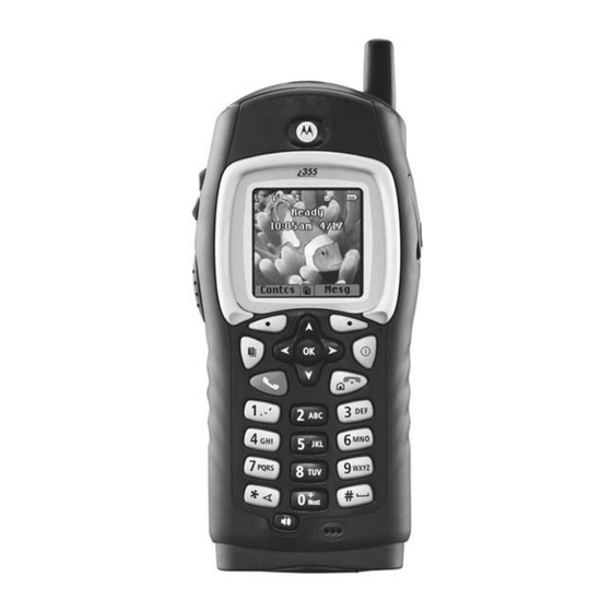
CHAPTER 2 COMPONENTS, ICONS, AND INDICATORS To conduct basic troubleshooting and maintenance of the i355 unit, you must become familiar with the components, display icons, and status indicators associated with the unit. Component Views The following figure shows the basic components of the i355 unit. Front View Rear View Antenna... -
Page 23: Display Icons
Depending upon features and options chosen, the following icons can appear on the i355 display. For more detailed information, refer to the iDEN i355 Digital Multi-Service Data-Capable Phone User’s Guide. Main Menu Icons Browser Browse the Web. -
Page 24: Status Icons
COMPONENTS, ICONS, AND INDICATORS: Display Icons Status Icons Status icons appear in the two rows at the top of the display. Some appear at all times. Others appear only when your phone is engaged in certain activities or when you have activated certain features. Battery Charge —... - Page 25 This page intentionally left blank.
-
Page 26: Displays, Messages, And Alerts
CHAPTER 3 DISPLAYS, MESSAGES, AND ALERTS To conduct basic troubleshooting and maintenance of the i355 unit, you must become familiar with the display screens, errors, messages, and alert tones associated with the unit. Power-Up Sequence Extend the antenna for optimum power and press momentarily to turn on the unit and begin the power-up sequence. -
Page 27: Power-Down Sequence
DISPLAYS, MESSAGES, AND ALERTS: Power-Down Sequence Power-Down Sequence To power down the unit, press for one second or more. Messages Self-Test Errors The following table contains the list of self-test non-reset errors. These errors are displayed as SELF CHECK ERROR YXXXX (YXXXX represents the identifier for that error). Table 3-1. -
Page 28: Service Messages
Try call again later Call Alert Target Not Authorized Target unit not authorized to Do not call unauthorized unit receive call Technical Error Unable to Problem detected with the GPS Reboot unit. If problem persists, contact Motorola Locate Sats circuitry 68P80400PXX-O... -
Page 29: Alert Tones
DISPLAYS, MESSAGES, AND ALERTS: Alert Tones Table 3-3. Service Messages (Continued) Message Cause Action Unable to locate Sats Unit does not have clear view of Make sure user is out in clear sky and stationary. If GPS satellites problem persists, reboot unit. Unknown User Unit unknown to system Report problem to provider... - Page 30 DISPLAYS, MESSAGES, AND ALERTS: Alert Tones Table 3-4. i 355 Alert Tones (Continued) Tone High Freq Cadence When Tone Occurs Interconnect Busy 480/ 1s off + 1s on 480Hz; Interconnect channel or line is 620Hz 1s off +1s on 620Hz continuous busy Invalid Key 900Hz...
- Page 31 DISPLAYS, MESSAGES, AND ALERTS: Alert Tones Table 3-4. i 355 Alert Tones (Continued) Tone High Freq Cadence When Tone Occurs Phone Ring (U.S.) Spkr Spkr Available ringer tones: Phone call received 2091/ 14x(24ms on 2091Hz + 24ms on 2556Hz 2556Hz) + 2.5s off 2230/ 14x(64ms on 2230Hz + 64ms on 2040Hz...
-
Page 32: Using The Optional Vibrate Function
DISPLAYS, MESSAGES, AND ALERTS: Using the Optional Vibrate Function Table 3-4. i 355 Alert Tones (Continued) Tone High Freq Cadence When Tone Occurs Talk Prohibit Spkr 900Hz Continuous PTT transmission not allowed TOT Warning Spkr 900Hz 1x80ms on Transmission rights expiring Valid Key Press 1800Hz 1x80ms on... - Page 33 DISPLAYS, MESSAGES, AND ALERTS: Using the Optional Vibrate Function To set unit to vibrate for Private (DC) and group calls (GC) only: 1. From the main menu, select Settings > DC/GC Options > Alert Type. 2. If Alert Type does not appear, from the main menu select Ring Tones. Make sure Vibe All or Silent All is set to Off.
-
Page 34: Preparing For Basic Level Testing
CHAPTER 4 PREPARING FOR BASIC LEVEL TESTING Testing the i 355 Unit To prepare the unit for testing, the antenna must first be removed. WARNING: When replacing the antenna, be sure to use the appropriate assembly for your model. Failure to use proper antenna assembly constitutes an FCC Grant Violation. - Page 35 PREPARING FOR BASIC LEVEL TESTING: Removing and Installing the Antenna Whip Assembly 4. Loosen counterclockwise and continue to unscrew with the antenna tool until the antenna assembly comes out completely. 5. Ensure the plastic Antenna Straw comes out with the antenna assembly. Do not deform the straw end, as it will prevent proper antenna operation when used again.
-
Page 36: Additional Test Equipment
PREPARING FOR BASIC LEVEL TESTING: Additional Test Equipment 5. Once the antenna assembly is screwed in as far as possible by hand, use the antenna tool to apply the final clockwise torque setting of 2.5 in. lb. Hand-tighten appropriately for a fine- thread screw fastener. - Page 37 This page intentionally left blank.
-
Page 38: Basic Level Checks And Self Tests
CHAPTER 5 BASIC LEVEL CHECKS AND SELF TESTS Before you perform basic troubleshooting and self tests on an i355 unit, determine if any special conditions could affect testing and check the units for defective parts. There are five categories of basic tests: •... -
Page 39: Basic-Level Test Checklist
BASIC LEVEL CHECKS AND SELF TESTS: Basic-Level Test Checklist Basic-Level Test Checklist Use the following checklist to ensure that all the necessary tests are performed and to provide a tracking mechanism in case the unit is sent to the next level of service. Check the appropriate box for each test performed and indicate whether or not the test was completed successfully. -
Page 40: Mechanical And Electrical Checks
BASIC LEVEL CHECKS AND SELF TESTS: Mechanical and Electrical Checks Mechanical and Electrical Checks Before conducting more complex tests, clean and check the unit for any mechanical defects that might cause or contribute to the problem. The following tests constitute the mechanical and electrical checks of the unit: •... -
Page 41: Accessory Swap Test
BASIC LEVEL CHECKS AND SELF TESTS: Mechanical and Electrical Checks 3. Clean the SIM card, if necessary, by wiping its surfaces with a clean, static-free cloth, and then check the contact areas in the unit for foreign material, damage, or other defects. 4. -
Page 42: Battery Connections Test
BASIC LEVEL CHECKS AND SELF TESTS: Mechanical and Electrical Checks Battery Connections Test Use this test to check the battery connections in the unit. The battery connections test time is approximately 5 minutes: 1. Remove the battery cover and battery from the unit. 2. -
Page 43: Voltage Recognition Test
BASIC LEVEL CHECKS AND SELF TESTS: Troubleshooting 7. Press RFRSH. The unit will respond with “Scanning for Satellites” or “Satellite Data Is Outdated, Continue?” depending upon whether the GPS Almanac is up-to-date or not. 8. If the unit responds with “Satellite Data is Outdated, Continue?” press YES, otherwise, no action is required. -
Page 44: Passcode Test
BASIC LEVEL CHECKS AND SELF TESTS: Self-Test Procedures of basic components. These procedures usually do not require test equipment other than a reference SIM card. The following self-tests can be performed on an i355 unit: • Passcode • Programming Menu Settings •... -
Page 45: Phone Calls Features
BASIC LEVEL CHECKS AND SELF TESTS: Self-Test Procedures • Language— sets the language that your phone displays. Phone Calls Features The Phone Calls menu controls how your phone handles phone calls: • Set Line— sets phone line 1 or phone line 2 as the active line for outgoing calls. •... -
Page 46: Volume Features
BASIC LEVEL CHECKS AND SELF TESTS: Self-Test Procedures DC/GC Options The DC/GC menu controls how your phone handles Direct Connect (DC) and Group Connect (GC) calls: • Tkgroup Silent — controls whether you hear group calls or call alerts to your Talkgroup. To receive group calls made to a Talkgroup, you must join the Talkgroup. -
Page 47: Security Features
BASIC LEVEL CHECKS AND SELF TESTS: Self-Test Procedures • Speaker — sets the volume of sound coming out of the speaker. • Keypad— sets the volume of sound associated with pressing keys and buttons. • Data—sets the volume of sounds that notifies you that you are receiving a circuit data call. Security Features The Security menu lets turn security features on and off and change passwords: •... - Page 48 BASIC LEVEL CHECKS AND SELF TESTS: Self-Test Procedures Press under Ok. • GPS PIN — enables and disables your phone’s GPS PIN security feature. To turn the GPS Enabled security feature on or off: From the main menu, select Settings > Security > GPS PIN. Scroll to On or Off.
-
Page 49: Advanced Features
BASIC LEVEL CHECKS AND SELF TESTS: Self-Test Procedures Advanced Features The Advanced menu contains advanced and low priority Settings features. • Alert Timeout — controls the amount of time a tone continues to sound when you receive a message notification or call alert. •... - Page 50 BASIC LEVEL CHECKS AND SELF TESTS: Self-Test Procedures 4. Press Menu > Settings > Volume (Speaker Volume), and use the Volume keys to set the speaker volume of the problem unit to 3 bars. 5. Verify that the problem unit performs within audio-quality standards. If defects such as distortion, hum, or screeching exist, replace the unit.
- Page 51 This page intentionally left blank.
-
Page 52: Basic Level Test Modes And Procedures
CHAPTER 6 BASIC LEVEL TEST MODES AND PROCEDURES To complete basic testing of an i355 unit, you must enter a test mode to retrieve data from the unit, and perform the technician tests in the correct sequence with the appropriate equipment. Test procedures are listed in the order in which they should be implemented. -
Page 53: Display Screens
BASIC LEVEL TEST MODES AND PROCEDURES: Test Modes Display Screens Display screens on the i355 unit provide information that is useful for troubleshooting purposes. These displays appear only when the unit is placed in debug mode (see “Entering Debug Mode on page 6-1). -
Page 54: Entering Test Mode
BASIC LEVEL TEST MODES AND PROCEDURES: Test Modes Table 6-1. Display Screens (Continued) Name Description IMEI/SIM ID Displays the electronic serial number and SIM ID serial number. The IMEI is the global name assigned to the mobile station at manufacturing time and should correspond to the serial-number tag of the unit. -
Page 55: Test Mode Test Procedures
BASIC LEVEL TEST MODES AND PROCEDURES: Test Mode Test Procedures Test Mode Test Procedures Enter debug or test mode to perform the following tests: • Audio Loopback Test • Engineering Debug Check Audio Loopback Test Use this test to check the functionality of the microphone and the audio quality of the earpiece. The loopback test checks the unit’s audio by passing a test signal from the Codec microphone input to the Codec Rx output. -
Page 56: Esn And Imei Matching Test
BASIC LEVEL TEST MODES AND PROCEDURES: Test Mode Test Procedures ESN and IMEI Matching Test Use this test to verify that the electronic serial number (ESN) matches the International Mobile Equipment Identifier (IMEI) on the Serial Number label located on the chassis of the unit. The ESM/IMEI matching test time is approximately 6 minutes: 1. - Page 57 BASIC LEVEL TEST MODES AND PROCEDURES: Test Mode Test Procedures g. Press Select to view the current software version programmed in the unit, as well as the software type (RSS model) and build date. 3. Press Back twice to return to the Trace Mode display. 4.
- Page 58 BASIC LEVEL TEST MODES AND PROCEDURES: Test Mode Test Procedures 14. Scroll down to highlight Err/Chan Codes, and then press On to view the Err/Chan Codes display. This screen displays the physical channel that the unit is connected to or the radio link procedure that is currently active.
-
Page 59: Technician Test Procedures
BASIC LEVEL TEST MODES AND PROCEDURES: Technician Test Procedures Technician Test Procedures Technician tests usually require special equipment to test the functionality of the components in the unit. The following tests check the software functionality of the unit: • Codeplug Repair Procedure •... -
Page 60: Codeplug Repair Procedure
BASIC LEVEL TEST MODES AND PROCEDURES: Connecting the Unit to the RSS Workstation Figure 6-1. Data Cable Programming Setup Refer to the Radio Service Software User’s Guide for more information on setting up your test computer as an RSS workstation. NOTE: For faster codeplug reading, enable the QuickComm feature in the RSS configuration setup. -
Page 61: Codeplug Troubleshooting
BASIC LEVEL TEST MODES AND PROCEDURES: Connecting the Unit to the RSS Workstation To prevent the loss of call lists, create a backup of the codeplug before attempting any form of modification. Refer to the Radio Service Software User’s Guide for instructions on reading and saving codeplug information. -
Page 62: Preparing For Field Level Testing
• Ground the working surface of your service bench. If possible, use the Motorola Static Protection Assembly (P/N 0180386A82) to ground your service bench. This assembly contains a wrist strap, two ground cords, a table mat, and a floor mat. -
Page 63: Using Rss
Prior to touching any printed-circuit board, touch an electrical ground to remove any static charge that might have accumulated. Refer to Service and Repair Note SRN-F1052 for more information. This note is available through: Motorola Literature Distribution Center 2290 Hammond Drive Schaumburg, IL 60173... - Page 64 PREPARING FOR FIELD LEVEL TESTING: Connecting an i355 unit to the R-2660 Coaxial Cable In/Out (N-type) R-2660 i205 Communications Unit Under Test System Unit Under Test attached here Analyzer Battery Eliminator 5.0 to 12.0 Vdc Power Supply Figure 7-1. R-2660 Setup To connect the unit to the R-2660: 1.
-
Page 65: Operating The R-2660
PREPARING FOR FIELD LEVEL TESTING: Operating the R-2660 8. Turn on the power supply, and adjust it for an output between 5.0 Vdc and 12.0 Vdc. NOTE: With the power supply voltage set between 5.0 Vdc and 12.0 Vdc, the battery eliminator will provide a regulated 4.0 Vdc to the unit. -
Page 66: Disassembling And Reassembling The Unit
PREPARING FOR FIELD LEVEL TESTING: Disassembling and Reassembling the Unit Disassembling and Reassembling the Unit Motorola recommends the service technician follow a prescribed disassembly sequence to access specific items or components of the unit. The i355 product is an efficiently designed package that incorporates the physical overlap and integration of some modular components. -
Page 67: Top And Bottom Caps
PREPARING FOR FIELD LEVEL TESTING: Top and Bottom Caps Top and Bottom Caps Required Tools: T-6 Torx bit, black stick. Preparation: Remove antenna. Remove: Bottom cap 1. Pry open the connector seal. (See Figure 7-2.) 2. Remove the three Torx T-6 screws. Do not mix with other screws. 3. -
Page 68: Back Bezel
PREPARING FOR FIELD LEVEL TESTING: Back Bezel Back Bezel Required Tools: Black stick. Remove: 1. Release the back bezel bottom catches. Maintain bezel separation. (See Figure 7-4.) NOTE: Excessive pressure can deform the back bezel bottom catches. Use care not to bend. 2. -
Page 69: Front Bezel
PREPARING FOR FIELD LEVEL TESTING: Front Bezel Front Bezel Preparation: Back bezel removed. Remove: 1. Place fingertips under each latch at top of front bezel. (See Figure 7-8.) 2. Pull up slightly on latches to clear tabs. Do not pull up on tabs more than necessary. 3. -
Page 70: Vibrator Assembly
PREPARING FOR FIELD LEVEL TESTING: Vibrator Assembly Vibrator Assembly Tools Required: Clean tweezers, mini flat-tipped 1/8" screwdriver. Remove: 1. Vibe Assembly has plastic jacket surrounding the vibe motor. At counterweight end, wedge and slide in tip of screwdriver between jacket and motor housing approximately 3/8". 2. -
Page 71: Main Keypad
PREPARING FOR FIELD LEVEL TESTING: Main Keypad Main Keypad Remove: 1. Reach into bezel, grasp edge of the keypad near top left boss, peel out in diagonal direction to lower right corner of bezel. (See Figure 7-18.) 2. Check key holes in bezel and surface of keypad for debris, dried fluids, etc. Figure 7-18. -
Page 72: Ptt-Volume Keypad
PREPARING FOR FIELD LEVEL TESTING: PTT-Volume Keypad PTT-Volume Keypad Tools Required: Black stick. Remove: 1. Lift the keypad/extender with the stick from the center of the pad at the PTT button to clear it from the alignment boss on the housing assembly. 2. -
Page 73: Gps Antenna
PREPARING FOR FIELD LEVEL TESTING: GPS Antenna Preparation: Back housing assembly removed; contains antenna bushing contact.Verify shape, condition, and spring to match with installation check. Remove: 1. Remove six T-6 screws holding front and back housings together. 2. In the back housing, locate the antenna bushing contact next to the GPS antenna compartment. 3. -
Page 74: Oval High Audio Speaker
PREPARING FOR FIELD LEVEL TESTING: Remove Oval High Audio Speaker Remove: 1. Locate the GPS antenna at the top of the back housing just above the vibrator. Note that the GPS antenna is held in place by four clips. (See Figure 7-24.) 2. - Page 75 PREPARING FOR FIELD LEVEL TESTING: Remove Oval High Audio Speaker 2. Locate underside of high audio seal assembly at contact pin channel and push with black stick until high audio seal releases. (See Figure 7-27.) Turn over and peel away rest of seal from grill. 3.
-
Page 76: Microphone Boot And Seal
PREPARING FOR FIELD LEVEL TESTING: Remove Microphone Boot and Seal Remove Microphone Boot and Seal Tools Required: Clean tweezers and black stick. Preparation: Housing assembly is separated and LCD module removed. CAUTION: When removing and installing the microphone boot or seal, do not touch with your bare fingers. -
Page 77: Lcd Module
PREPARING FOR FIELD LEVEL TESTING: Remove LCD Module Remove LCD Module Tools Required: Black stick. Preparation: Housing assembly separated from bezels. Remove: 1. Remove T-6 screws holding the housing assembly together. 2. Fan out front and back housings that main board is accessible with no stress on the LCD module flex ribbon. - Page 78 PREPARING FOR FIELD LEVEL TESTING: Remove LCD Module Install: Preparation: Housing assembly is separated. 1. Position LCD module in compartment so that boss holes and boss pins align. 2. Push LCD module into top of compartment to engage 11 and 1 o’clock top clips first. 3.
-
Page 79: Earpiece Transducer And Seal
PREPARING FOR FIELD LEVEL TESTING: Earpiece Transducer and Seal Earpiece Transducer and Seal Tools Required: None. Preparation: Housings separated, main board set aside, LCD module removed. Remove: 1. Locate the transducer opening in the front housing and push the transducer with transducer seal through the opening. -
Page 80: Exploded Views And Parts Lists
PREPARING FOR FIELD LEVEL TESTING: Exploded View and Parts List Exploded View and Parts List The table and figure that follow provide a list of the components in the i355 unit. 7-19 68P80400PXX-O... -
Page 81: Component Parts List
PREPARING FOR FIELD LEVEL TESTING: Exploded View and Parts List Component Parts List Description Part Number Kit Number Ring, Lens 1315226H01 Lens 6115225H01 Bezel, Front Assembly 1315238H01 Cap, Top 1385560F03 Felt, Transducer 3515232H01 Reflector Assembly, Transducer 2615239H01 Seal, Audio Jack 3264004H01 Pin, Audio Jack Retainer 2285885E01... -
Page 82: Exploded View
PREPARING FOR FIELD LEVEL TESTING: Exploded View and Parts List Exploded View 7-21 68P80400PXX-O... - Page 83 This page intentionally left blank.
-
Page 84: Field Level Test Modes And Procedures
CHAPTER 8 FIELD LEVEL TEST MODES AND PROCEDURES To perform field level testing on the i355 unit, you must enter a test mode to retrieve data from the unit, and perform the technician tests in the correct sequence with the appropriate equipment. NOTE: All tests should be performed in an RF interference-free environment. -
Page 85: Entering Test Mode
FIELD LEVEL TEST MODES AND PROCEDURES: Test Modes Entering Test Mode Use this procedure to access test mode. To enter test mode: Power up the unit. Wait until registration is complete before continuing. NOTE: Steps 2 through 7 must be performed quickly (no more than one second between each key press). -
Page 86: Field-Level Test Checklist
FIELD LEVEL TEST MODES AND PROCEDURES: Field-Level Test Checklist Field-Level Test Checklist Use the following test checklist to ensure that all the necessary tests are performed and to provide a tracking mechanism in case the unit is sent to the next level of service. Check the appropriate box for each test performed and indicate whether or not the test was completed successfully. -
Page 87: Registration/Call Test
NOTE: Use a “golden” or reference unit to get a baseline. Note: For 900 MHz verification, please perform the RX BER Test on page 8-7. May require ordering additional option for test. Contact Motorola Customer Service (see Appendix A). Notes:... -
Page 88: Sqe Test
FIELD LEVEL TEST MODES AND PROCEDURES: SQE Test SQE Test Use this test on unit’s exhibiting poor performance in known good coverage area. Symptoms may include: * No service failures or poor SQE/RSSI. Notes: Set up the R-2660 for iDEN Mobile operation, and connect the Watch unit for resetting during this procedure. -
Page 89: Tx Power Test
FIELD LEVEL TEST MODES AND PROCEDURES: TX Power Test TX Power Test Use this test on unit’s exhibiting Bad Transmission (TX) or Intermittent Service failures. NOTE: This is a Transmitter test only: Notes: Set up the R-2660 for Spectrum Place the unit into Test Mode for this test. Analyzer display, and Unit will transmit at greater than 24 dBm. -
Page 90: Rx Ber Test
FIELD LEVEL TEST MODES AND PROCEDURES: RX BER Test RX BER Test Use this test on unit’s exhibiting any of the following: “RAAAA Type” resets, No Service failures. Notes: Set up the R-2660 for iDEN RX BER Test, and connect the unit to the RF Confirm the reset log has errors. -
Page 91: Power-Up Test
FIELD LEVEL TEST MODES AND PROCEDURES: Power-Up Test Power-Up Test Use this test to check Power-Up operation. Symptoms include any of these: * Dead battery. * Short battery life. * Unit does not power up. Try to power up the unit. Pass Swap the Display Verify... -
Page 92: Audio Test
FIELD LEVEL TEST MODES AND PROCEDURES: Audio Test Audio Test Use this procedure to test the unit’s Audio section: Notes: Set up the R-2660 for iDEN Mobile operation, and connect the Verify that the unit can pass the SQE test before performing the unit to the RF IN/OUT connector. -
Page 93: Reset Test
FIELD LEVEL TEST MODES AND PROCEDURES: Reset Test Reset Test Use this test on a unit exhibiting one or more of the following symptoms: * Unit resets. * Unit powers off, then powers on. Notes: Set up the R-2660 for iDEN Mobile operation, and connect the Verify the unit has resets entries in the Reset log. -
Page 94: Reset Log Test
FIELD LEVEL TEST MODES AND PROCEDURES: Reset Log Test Reset Log Test Use this procedure to check the unit’s Reset Error Log capability: 1. Power on the unit and wait until registration is complete. 2. If the unit does not have the latest software version, reflash (reprogram) the unit. If the unit attempts to reset, perform the Reset test (see page 8-11). -
Page 95: Model Assembly (Ma) Test Mode Test
Model Assembly Test Mode is an embedded series of operational tests of the unit's user interface and functional features. • Motorola iDEN recommends MA Test Mode be performed after any servicing of the unit. • An Audio Test Cable is required to complete test mode correctly. See the Required Tools section or contact Motorola’s Aftermarket Accessories Division. -
Page 96: Gps Receiver
FIELD LEVEL TEST MODES AND PROCEDURES: GPS Receiver GPS Receiver Use this procedure to check the unit’s ability to coordinate with GPS: Find an open sky area. Turn unit Obtain reference Activate receiver. Phone Location returns coordinates location working. coordinates similar working. -
Page 97: Mototalk
FIELD LEVEL TEST MODES AND PROCEDURES: MOTOtalk MOTOtalk Use this procedure to test MOTOtalk without additional test equipment: Place Radio Under Test and a Golden Radio into MOTOtalk Mode: 1. Main menu. 2. Scroll to MOTOtalk. 3. OK. 4. Scroll to “GO TO MOTOtalk”. 5. -
Page 98: Ordering Replacement Parts And Kits
ORDERING REPLACEMENT PARTS AND KITS Parts should be replaced with identical replacement parts. Replacement parts and kits for can be ordered directly from the Motorola Accessories and Aftermarket Division (AAD) at 1-800-422-4210 and listen to the prompts; or FAX 1-800-622-6210. -
Page 99: Replacement Kits
Replacement Kits When ordering replacement kits, the complete kit number should be included. If the correct number cannot be located, call Motorola Parts Identification at 1-800-422-4210. Refer to the exploded views in Chapter 7. Table A-1. i 355 Replacement Kits... - Page 100 Digital Camera Assembly NNTN5407A Digital Camera Case NNTN5408A Digital Camera Retail Kit NTN2072A Digital Camera Software Installation CD NVN5312A Klaus Power Plug Adapters: Euro Plug SYN7456A UK Plug SYN7455A Aus/NZ Plug SYN8127A Korean Plug SYN7460A Escutcheon Labels: Motorola NNTN5399A 68P80400PXX-O...
-
Page 101: Recommended Test Equipment And Tools
8185377F01 Battery Eliminator NNTN4807A Black Stick SLN7223A Cable, Audio Jack Test NNTN5171A Cable, SMA to N-Type RF Contact Motorola Communications System Analyzer Motorola R-2660 Data Cable, RS-232 (Serial Port) NKN6560A Data Cable, USB NKN6559A Digital Volt-Ohm Meter Keithly 2001 or eq. - Page 102 INDEX conditions, test connecting to RSS workstation accessories conventions, manual reference Corrupted Software Repair procedure 6-10 Accessory Swap test Customer Care, contacting alert tones customer service, contacting allocating time altering RF signals antenna considerations debug mode Audio Loopback test digital Audio test 8-10 bit stream...
- Page 103 INDEX interconnect mode pages parts Keypad test accessories ordering kits replacement ordering replacement parts list exploded view 7-21 Passcode test PCCH Lockup test See primary control channel power-down sequence power-up sequence mechanical checks Power-Up test Accessory Swap Audio Loopback preventive maintenance basic primary control channel (PCCH) Battery Connections...
- Page 104 INDEX Registration/Call test slot number related publications specifications, model viii repetition rate SQE Test replacement static-sensitive devices, protecting kits strong-signal environments parts replacement parts domestic orders TDMA international orders See Time Division Multiple Access listing technician tests reset condition Audio 8-10 reset errors Codeplug Repair Procedure...
- Page 105 INDEX equipment preparation dual band ESN and IMEI Matching equipment preparation GPS Receiver 8-13 errors Lockup icons Model Assembly (MA) Test Mode 8-12 LED indicators MOTOtalk 8-14 mechanical checks Passcode messages Power-Up power-down sequence preparing for power-up sequence Programming Menu Settings Check preparing for testing Registration/Call programming...
- Page 106 Motorola Confidential Proprietary © 2005 by Motorola, Inc. @6880400PXX@ 8000 W. Sunrise Blvd. Ft. Lauderdale, FL 33322 68P80400PXX-O Printed in U.S.A. 03/05. All Rights Reserved.
Need help?
Do you have a question about the iDEN i355 and is the answer not in the manual?
Questions and answers