Table of Contents
Advertisement
Quick Links
Advertisement
Table of Contents

Subscribe to Our Youtube Channel
Related Manuals for Yolin YL91F-E


Summary of Contents for Yolin YL91F-E
- Page 1 Electric Bike Display User’s Manual YL91F-E Tianjin Yolin Technology Co. Ltd.
-
Page 2: Table Of Contents
TABLE OF CONTENTS 1. PRODUCT NAME AND MODEL NUMBER ..........................1 2. SPECIFICATION ..................................1 3. APPEARANCE AND SIZE ................................1 4. FUNCTION OVERVIEW AND FUNCTIONAL AREAS ........................3 4.1 F ..............................3 UNCTIONAL OVERVIEW 4.2 F ................................. 3 UNCTIONAL AREAS 4.3 B .............................. - Page 3 9. WIRE CONNECTION DIAGRAM ............................... 17 9.1 S .......................... 17 TANDARD WIRE CONNECTION SEQUENCE 10. PRECAUTIONS ..................................17 SCHEDULE 1: ERROR CODE DEFINITION ............................. 18...
-
Page 4: Product Name And Model Number
1. Product Name and Model Number Smart LCD display for electric bicycle; Model: YL91F-E. 2. Specification ● 48V power supply ● Display rated current 15mA ● Display maximum current 30mA ● Shutdown leakage current <1uA ● Supplied current to the controller 50mA ●... - Page 5 Figure 3-2 Physical picture of the K5 control button Figure 3-3 91F-E Front View Dimension Figure 3-4 91F-E Side View Dimension...
-
Page 6: Function Overview And Functional Areas
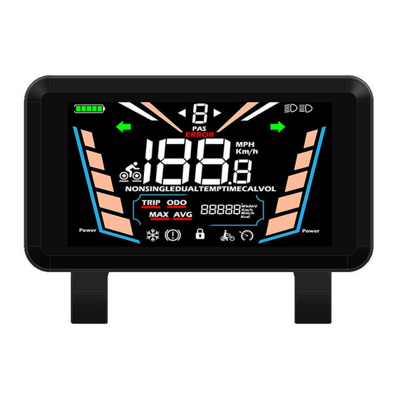
Walk boost Average speed Cruise control Figure 4-1 YL91F-E functional area distribution interface 4.3 Button definitions The YL91F-E display is equipped with five buttons on the corresponding operating unit: power on/off , plus minus , light and toggle 5. Routine operation 5.1 Power on/off... -
Page 7: Display Interface Switching
5.2 Display interface switching When the display is powered on, it will show the Current Speed (km/h) and Trip Odometer (km) by default. Short press to switched cyclically between Trip Odometer(km), Odometer (km), Maximum Speed (km/h), and Average Speed (km/h). Odometer Trip Odometer Average speed... -
Page 8: Walk Boost Mode
5.3 Walk boost mode Long Press and hold , the electric bicycle enters the walk boost mode. Your e-bike will run at the constant speed at the promoted speed and the display shows . Release to stop the power output immediately and restore to the state before walk boost. -
Page 9: Quick Switching Operation Of Dual Drive Mode
5.6 Quick switching operation of dual drive mode Long press and hold the on the main interface of the display, three driving modes can be quickly cycled for switching,when switching, The left side of the display indicates the current switching status. (When in rear wheel drive, the stars inside the rear tires always light up, when in front wheel drive, the stars inside the front tires always light up, and when in full-time dual drive, the stars inside the front and rear tires flash simultaneously) rear wheel drive... -
Page 10: Personalized Parameter Settings
6. Personalized parameter settings Each setting needs to be done with the bicycle stationary. The personalized parameter setting procedure is as follows: When the display is ON and the speed shows 0, (1) Press and hold simultaneously for more than 2 seconds to enter the personalized parameter setting interface. -
Page 11: Rated Voltage Setting
6.2 Rated voltage setting 02P is the rated voltage setting. The available rated voltage range is: 36V, 48V, 60V. Press to enter the parameter changing state. Press the to select the parameter and press to save the parameter setting and return to the personalized parameter setting interface. Figure 6-2 Rated voltage setting interface 6.3 PAS level setting 03P is the Pedal assist (PAS) level setting. -
Page 12: Wheel Diameter Setting
6.4 Wheel diameter setting 04P is the wheel diameter setting. The adjustable wheel diameter range is: 8~32inch. Press to enter the parameter changing state. Press the to select the parameter and press to save the parameter setting and return to the personalized parameter setting interface. Figure 6-4 Wheel diameter setting interface 6.5 Number of speed sensor magnets setting 05P is the speed sensor magnet number setting. -
Page 13: Speed Limit Setting
6.6 Speed Limit Setting 06P is the speed limit setting. The adjustable speed limit range is: 1~52km/h. (The maximum adjustable speed limit varies by different protocols) Press to enter the parameter changing state. Press the to select the parameter and press to save the parameter setting and return to the personalized parameter setting interface. -
Page 14: Drive Mode Setting
6.8 Drive mode setting 08P is the drive mode setting. The available drive modes are: 00→Pedal assist only, 01→Electric only, 02→Both Pedal assist and electric. Press to enter the parameter changing state. Press the to select the parameter and press to save the parameter setting and return to the personalized parameter setting interface. -
Page 15: Pedal Assist Strength Setting
6.10 Pedal assist strength setting 10P is the Pedal assist strength setting. The Pedal assist strength is the relative strength of the PWM signal from the controller when start to activate pedal assist. The adjustable range is 0 ~ 5. 0 is the weakest strength and 5 is the strongest. Press to enter the parameter changing state. -
Page 16: Controller Current Limit Setting
6.12 Controller Current Limit Setting 12P is the controller current limit setting. The adjustable range is: 1~50A. Press to enter the parameter changing state. Press the to select the parameter and press to save the parameter setting and return to the personalized parameter setting interface. Figure 6-12 Controller current limit setting interface 6.13 Battery under voltage value setting 13P is the battery under voltage setting. -
Page 17: Auto Sleep Time Setting
6.14 Auto Sleep Time Setting 14P is the auto sleep time setting. To save the battery power and reach higher range, this display will be turned off after it has not been used for a time. The adjustable range is: 00~60min, 00 means no auto shutdown. The factory default setting is 10 minutes. -
Page 18: Shortcut Operation
7. Shortcut operation 7.1 Restore factory default parameter settings operation dEF is the restore factory default parameter settings. dEF-Y is to restore the factory default settings, and dEF-N is not to restore. Enter into the main setting interface and keep the speed at 0, press and hold simultaneously for 2s to enter the restore factory default setting interface. -
Page 19: Trip Odometer Reset Operation
7.2 Trip odometer reset operation The display can record trip odometer and odometer. Trip odometer is not automatically reset after turning off. The trip odometer needs to be reset manually. The odometer can not be reset. Enter into the main setting interface and keep the speed at 0, press and hold simultaneously for 2s to reset the trip odometer. -
Page 20: Quality Assurance And Warranty
8. Quality Assurance and Warranty 8.1 Warranty info ● Yolin will offer a limited warranty for any failure caused by the product defects under normal use during the warranty period. ● The product is warranted for 12 months from the date out of factory. - Page 21 Brake failure breakdown E003 Hall failure E006 Motor phase failure Tel: 022-86838795 Fax: 022-86838795 Email: yolin@yolintech.com Website: www.yolintech.com Address: Tianjin Beichen District, Tianjin Beichen Economic Development Zone, Medical Equipment Industrial Park, East of Jingfu Highway, Ugu New Science Park 52-1 plant...
Need help?
Do you have a question about the YL91F-E and is the answer not in the manual?
Questions and answers
I purchased a Fucare Gemini X Sport dual motor e-bike. My display doesn’t have a parameter to change the speed settings. Please advise.