Table of Contents
Advertisement
Advertisement
Table of Contents

Subscribe to Our Youtube Channel
Related Manuals for Yolin YL80C


Summary of Contents for Yolin YL80C
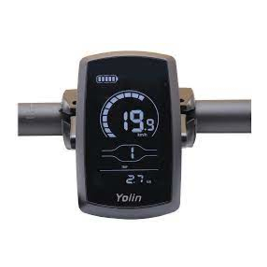
- Page 1 The eBike Display User's Manual YL80C...
-
Page 2: Table Of Contents
Content Product Name and Model.................................. 1 Specification Parameters..................................1 Appearance Dimensions..................................1 ◆ Physical Drawing and Dimensional Drawing (unit: ............................Functional Overview and Functional Area Distribution........................ 3 Function Overview..................................3 ◆ Functional Area Distribution..............................3 ◆ Button Definition..................................4 ◆ General Operations.................................... - Page 3 Key Assisted Push Enable Settings............................13 Slow Start Settings................................... 14 Boot Password Settings................................14 ◆ Boot Password Enable................................14 Switch-on Password Modification............................15 Exit Settings....................................15 ◆ Restore Default Settings................................... 15 Quality Commitment and Warranty Scope........................... 16 Lead Connection Diagram................................16 Precautions......................................
-
Page 4: Product Name And Model
Product Name and Model Intelligent Liquid Crystal Instrument for Electric Bicycle; Model: YL80C. Specification Parameters 24V/36V/48V power supply ● Rated working current of instrument 10mA ● The maximum working current of the instrument is 30mA ● Shutdown leakage current < 1uA ●... - Page 5 Physical Drawing and Dimensional Drawing...
-
Page 6: Functional Overview And Functional Area Distribution
Functional Overview and Functional Area Distribution Function Overview ◆ YL80C meters provide a variety of functions to meet your riding needs, including: Electricity Display ● Motor power indication ● Boost gear adjustment and indication ● Speed display (including real-time speed, maximum speed and average speed) ●... -
Page 7: Button Definition
Button Definition ◆ There are five keys on the corresponding operation unit of YL80C instrument, of which the keys are replaced by the words "UP" and "DOWN" respectively in the following instructions. General Operations Power On/Off ◆ After pressing the key... -
Page 8: Turn The Backlight On/Off
Helping to Promote Display Interface The boosting function can only be used when the user pushes the electric vehicle, and should not be used in the ◆ riding state. Turn the Backlight On/Off ◆ Press the headlight key briefly to dim the backlight of the instrument and notify the controller to turn on the headlight at the same time. -
Page 9: Electricity Display
Electricity Display ◆ The five-segment display of battery power shows that when the battery voltage is high, the five-segment LCD is on, and when the battery is under-voltage, the outer frame of the battery flashes at a frequency of 1HZ, indicating the need to charge immediately. -
Page 10: Backlight Brightness
TC stands for clearing the single mileage. Y/N can be selected through the UP/DOWN key, and “Y” means clearing the mileage of a single ride. “N” means a single ride that is not cleared Line mileage. Press the "i" key briefly to confirm and enter the backlight brightness setting state. Single Mileage Clearing Operation Interface Backlight Brightness ◆... -
Page 11: General Parameter Settings
General Parameter Settings Press and hold the UP + DOWN key for more than 2 seconds At the same time to enter the normal setting state. Press and hold the DOWN + i key for more than 2 seconds at the same time to enter the wheel diameter setting interface. Wheel Diameter Settings ◆... -
Page 12: Battery Charge Setting
Personalization Item Selection Interface Battery Charge Setting ◆ VOL represents voltage and requires 1 to 5 voltage values to be input one by one. Take the first electric quantity value as an example: "1" in the screen represents the first voltage and "34.5" is the first electric quantity value. Add/subtract settings are made through UP/DOWN key, press "i"... -
Page 13: Assist Proportion Value Setting
Booster Gear Selection Interface Assist Proportion Value Setting By setting the value of the assistance ratio, the speed of each gear can be adjusted to meet the needs of different riders. Take 1st gear as an example, "45-55%" is the range of 1st gear assistance ratio, and "50%" is the default value of 1st gear, which is a settable value. -
Page 14: Boost Sensor Settings (Option)
Boost Sensor Settings (Option) ◆ Direction Setting of Assist Sensor PAS stands for the booster sensor, and run-F/b is displayed on the screen. run-F stands for the forward direction and run-b stands for the reverse direction; Through the UP/DOWN key , press the "i" key briefly to confirm and enter the sensitivity setting of the power sensor. -
Page 15: Speed Sensor Settings (Option)
Assist Disk Magnetic Steel Number Setting Interface Speed Sensor Settings (Option) ◆ SPS represents a speed sensor, which can be set according to the number of magnetic heads installed on the wheels of the electric vehicle, with a setting range of 1-15; Modify by pressing UP/DOWN key for a short time, press "i" key for a long time to confirm and return to the instrument setting item selection interface. -
Page 16: System Settings (Options)
Rotating Handle Gear Enable Setting Interface System Settings (Options) ◆ Electricity Delay Time Setting dLY represents the power delay time, and the power delay time of 3/6/12s can be selected through UP/DOWN key. Press the "i" key briefly to confirm and enter the maximum speed limit setting interface. The instrument factory defaults to Electricity Delay Time Selection Interface Key Assisted Push Enable Settings PUS represents the push enable of the key, Y/N can be switched through the UP/DOWN key, Y represents the enable,... -
Page 17: Slow Start Settings
Slow Start Settings SSP stands for slow start, with an adjustable range of 1-4, and 4 stands for the slowest. You can select through the UP/DOWN key, press the "i" key for a long time to confirm and exit the setting. Instrument factory default 1. Slow Start Setting Interface Boot Password Settings ◆... -
Page 18: Switch-On Password Modification
Password Enable Confirmation Interface Switch-on Password Modification The instrument displays P3. Press the "i" key briefly to shift, and add/subtract the input value through the UP/DOWN key. After modification, press the "i" key for a long time to save and confirm, and exit the setting interface. Restarting the instrument will display P1, 0000, and the instrument will not work normally until the correct password is entered. -
Page 19: Quality Commitment And Warranty Scope
Restore Default Settings Interface Quality Commitment and Warranty Scope I. Warranty Information: 1. The Company will be responsible for providing limited warranty during the warranty period for any failure caused by the quality problem of the product itself under normal use conditions. 2. -
Page 20: Precautions
Precautions Pay attention to safety during use, and do not plug and unplug the instrument under the condition of power supply. Try to avoid bumping on the instrument. ◆ Regarding the background parameter setting of the instrument, please do not change it at will, otherwise ◆...
Need help?
Do you have a question about the YL80C and is the answer not in the manual?
Questions and answers
Nefunguje ukazovanie rychlosti na LCD displey YL80c.(ebike Avaka k200)