Table of Contents
Advertisement
Advertisement
Table of Contents

Related Manuals for Yolin YL80C


Summary of Contents for Yolin YL80C
- Page 1 User Manual for E-bike Display YL80C Tianjin Yolin Technology Co., Ltd.
-
Page 2: Table Of Contents
Table of Contents 1. PRODUCT NAME AND MODEL ..............................1 2. SPECIFICATIONS ..................................1 3. APPEARANCE AND DIMENSIONS ...............................1 4. FUNCTION OVERVIEW AND FUNCTIONAL AREA LAYOUT ......................2 4.1 F .................................2 UNCTION OVERVIEW 4.2 F ..............................2 UNCTIONAL AREA LAYOUT 4.3 B ................................. 3 UTTON DEFINITIONS 5. - Page 3 9. OUTGOING LINE CONNECTION DIAGRAM ..........................18 9.1 W ....................... 18 IRING SEQUENCE OF STANDARD CONNECTOR 10. CONSIDERATIONS ................................. 18SCHEDULE 1 ERROR CODE DEFINITIONS ........................18SCHEDULE 2: ASSIST LEVEL RATIO DEFAULT VALUES ....................。...
-
Page 4: Product Name And Model
1. Product name and model Intelligent LCD display for e-bike; model: YL80C. 2. Specifications ● 48V power supply ● Rated working current 15mA ● Maximum working current 30mA ● Leakage current at power-off <1uA ● Working current at the supply controller end 50mA ●... -
Page 5: Function Overview And Functional Area Layout
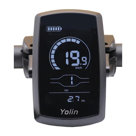
Fig. 3-4 Side View of Display 80C Dimensions 4. Function overview and functional area layout 4.1 Function overview Display YL80C provides a variety of functions to meet your riding needs, including: ● Battery level indicator ● Assist level adjustment and indication ●... -
Page 6: Button Definitions
4.3 Button definitions There are five buttons on the operating unit of display YL80C, i.e., the on/off button , plus button , minus button , headlight button and switching button 5. General operation 5.1 Power on/off By pressing and holding the button , the display will start to work and the working power supply of the controller will be turned on. -
Page 7: Push Assistance
5.3 Push assistance By pressing and holding the button , the electric push assistance mode will be enabled. Your e-bike will run at the constant speed at the promoted speed. The display will show . By releasing the button , your e-bike will immediately stop power output and return to the state before push assistance. -
Page 8: Assist Level Selection
5.5 Assist level selection By pressing the button , the e-bike assist level will be switched to change the motor output power. Fig. 5-4 Assist Level Switching Interface 5.6 Battery level indicator The battery level indicator consists of five segments. When the battery is fully charged, the five segments will be all on. In case of undervoltage, the outline of the battery indicator will flash, which means the battery has to be charged immediately. -
Page 9: Personalized Parameter Settings
6. Personalized parameter settings ■ All parameters can only be set when your e-bike stops. The steps for general setting are as follows: In the power-on state, when the display shows the speed of 0, (1) (1) Press and hold the buttons at the same time for more than 2 seconds to enter the personalized parameter setting interface;... -
Page 10: Metric/Imperial System Setting
6.2 Metric/imperial system setting 02P refers to the metric/imperial system setting option. 01 represents the imperial system, and 00 represents the metric system. Press the button to enter the parameter modification interface. Press the button for parameter selection. Press the button to save the parameter and return to the selection interface of general setting options. -
Page 11: Auto Sleep Time Setting
6.4 Auto Sleep Time Setting 04P is the auto sleep time setting. To save the battery power and reach higher range, this display will be turned off after it has not been used for a time. The adjustable range is: 1~60min, 00 means no auto shutdown. The factory default setting is 10 minutes. -
Page 12: Wheel Diameter Setting
6.6 Wheel diameter setting 06P is the wheel diameter setting. The adjustable wheel diameter range is: 1~32inch. Press to enter the parameter changing state. Press the to select the parameter and press to save the parameter setting and return to the personalized parameter setting interface. Figure 6-7 Wheel diameter setting interface 6.7 Number of speed sensor magnets setting 07P is the speed sensor magnet number setting. -
Page 13: Speed Limit Setting
6.8 Speed Limit Setting 08P is the speed limit setting. The adjustable speed limit range is: 1~100km/h. (The maximum adjustable speed limit varies by different protocols). Press to enter the parameter changing state. Press the to select the parameter and press to save the parameter setting and return to the personalized parameter setting interface. -
Page 14: Drive Mode Setting
6.10 Drive mode setting 10P is the drive mode setting. The available drive modes are: 00→Pedal assist only, 01→Electric only, 02→Both Pedal assist and electric. Press to enter the parameter changing state. Press the to select the parameter and press to save the parameter setting and return to the personalized parameter setting interface. -
Page 15: Pedal Assist Strength Setting
6.12 Pedal assist strength setting 12P is the Pedal assist strength setting. The Pedal assist strength is the relative strength of the PWM signal from the controller when start to activate pedal assist. The adjustable range is 0 ~ 5. 0 is the weakest strength and 5 is the strongest. Press to enter the parameter changing state. -
Page 16: Controller Current Limit Setting
6.14 Controller Current Limit Setting 14P is the controller current limit setting. The adjustable range is: 1~50A. Press to enter the parameter changing state. Press the to select the parameter and press to save the parameter setting and return to the personalized parameter setting interface. Figure 6-15 Controller current limit setting interface 6.15 Battery under voltage value setting 15P is the battery under voltage setting. -
Page 17: Odo Resets Setting
6.16 ODO resets setting 16P is the ODO resets setting. The display can choose the following: 00→non reset, 01→reset. Press to enter the parameter changing state. Press the to select the parameter and press to save the parameter setting and return to the personalized parameter setting interface. Figure 6-17 ODO resets setting interface 6.18 6km/h walk boost setting 18P is the 6km/h walk boost setting. -
Page 18: Power-On Password Setting (Option)
6.19 Power-on password setting (option) 19P is the power-on password setting. The power-on password is not activated by default but users can activate it from setting PSd-y. The factory default password is 1212. Users can set other four-digit password. Please keep the password in mind after changing it, otherwise you will not be able to use the display. -
Page 19: Shortcut Operation
Figure 6-20 Power-on Password Activated interface Figure 6-21 Power-on Password OFF interface In the password setting mode, the adjustable digit will flash. Press the to select the parameter and press to save the numbers and go to the next digit setting. Long press to save the parameter setting and return to the personalized parameter setting interface after finish setting the four digits in turn. -
Page 20: Quality Commitments And Warranty Scope
7.2 Trip odometer reset operation The display can record trip odometer and odometer. Trip odometer is not automatically reset after turning off. The trip odometer needs to be reset manually. Enter into the main setting interface and keep the speed at 0, press and hold simultaneously for 2s to reset the trip odometer. - Page 21 9. Outgoing line connection diagram 9.1 Wiring sequence of standard connector Projection Groove Connecting terminal to the Leading-out terminal of display Connecting terminal controller Fig. 8-1 Outgoing Line Connection Diagram Table 8-1 Wiring Sequence of Standard Connector Standard wiring sequence Standard wire color Function Red (VCC)
- Page 22 Check that the display cable is properly Error11 transmission failure connected Tel: 022-86838795 Fax: 022-86838795 Email: yolin@yolintech.com Website: www.yolintech.com Address: Plant 52-1, Yougu Xinke Park, East of Jingfu Road, Pharmaceuticals and Medical Equipment Industrial Park, Beichen Economic Development Zone, Beichen District, Tianjin...
Need help?
Do you have a question about the YL80C and is the answer not in the manual?
Questions and answers