
Related Manuals for Intellitec ICX-OLED


Summary of Contents for Intellitec ICX-OLED
- Page 1 OLED DIN Switch Panel USER MANUAL V2.01 29/01/24 Technical Helpline +44 (0) 151 482 8970 www.intellitecmv.com 1110R-05 11529 Page 1...
- Page 2 Intellitec MV Ltd reserves the right to update this document (User’s Manual) without notification at any time. You will find the latest documents for our products on our website: www.intellitecmv.com...
-
Page 3: Specification
PRODUCT OLED DIN Switch Panel Specification Input Voltage (Volts DC) 9-32V Max Input Current (A) 1.5A Standby Current Consumption (mA) 50mA IP Rating of module Ip20 Weight (g) 112g Dimensions L x W x D (mm) 185x58x22mm Inputs Outputs 12x Programmable Switches 12x Programmable Button Backlights 4x Analogue Inputs OLED Display... -
Page 4: Installation
INSTALLATION OLED DIN Switch Panel Dimensions (mm) Connector Plug Wiring Connector Description Manufacturers Part Number Module Connector Molex 16-Way Female Housing 46992-1610 Cable Entry View 01. Input 1. 02. Input 2. 03. PMC Blue Loop. 04. ADC Input 1. 14 13 11 10 05. - Page 5 Configuration OLED DIN Switch Panel iConnex: When configured to communicate with the iConnex module, the keypad uses 2 keypad IDs and 3 Slave IDs. To configure the IDs, hold ‘Button 1' down during startup. The Auxiliary slave module may only be configured using firmware. As there are no audio functions within the OLED DIN switch unit, both the audio and graphical slave modules are configured for graphics.
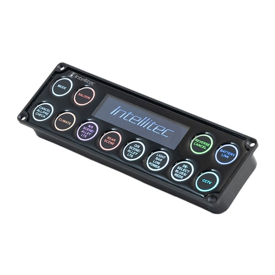
- Page 6 Switches OLED DIN Switch Panel Buttons: The OLED DIN Switch Panel has 12 Buttons numbered 1 to 12 from the top left to the bottom right. SWITCH SWITCH SWITCH SWITCH SWITCH SWITCH SWITCH SWITCH SWITCH SWITCH SWITCH SWITCH Button Lighting: Each button has individual RGB LED lighting which allows for independent colours to be configured.
-
Page 7: Side Door Open
Display OLED DIN Switch Panel Start Up Screen: The OLED display will show a logo during start up, this can be set to a customer specific logo. Messages: The OLED display can show messages up to 3 lines of text and an icon, these messages can be configured with a priority and a display time. - Page 8 Inputs OLED DIN Switch Panel Digital Inputs: There are 4 digital inputs, configurable to be either active high or an active low. iConnex Mode: The Graphical slave inputs 1-4 are triggered by inputs 1-4. PMC Mode: The inputs will trigger the respective configured PMC channels. Analogue Inputs: There are 4 analogue ADC voltage inputs.
- Page 9 Outputs OLED DIN Switch Panel Buzzer: A PCB Mounted buzzer can be configured to sound during either an active alarm or button press (timed). The buzzer can also be sounded using either auxiliary output 12 or a configured PMC Channel Switched Outputs Positive Output: There is a low power switched positive pin (Pin 12) located on the rear of the OLED DIN, this can be...
Need help?
Do you have a question about the ICX-OLED and is the answer not in the manual?
Questions and answers