Advertisement
- 1 INTRODUCTION
- 2 TECHNICAL SPECIFICATIONS
- 3 ELECTRICAL CONNECTION
- 4 INSTALLATION USING A TRANSMITTER
- 5 HOW TO MEMORIZE/DELETE A RADIO DEVICE
- 6 FINE ADJUSTMENT OF UPPER LIMIT SWITCH
- 7 MODIFY BOTH THE LIMIT SWITCHES
- 8 FAVORITE POSITION
- 9 SUN,WIND, RAIN SENSORS
- 10 OPERATION LOGIC OF COMMAND BUTTONS
- 11 TEST RADIO
- 12 TENSIONING ADJUSTMENT
- 13 RESET
- 14 WARNINGS
- 15 Documents / Resources
INTRODUCTION
This manual describe the operations for a correct installation of LINE. The tubular motors with electronic limit switch LINE series are suitable to command pergolas. The technical characteristics are provided on the label stuck on motor. These devices have not been studied to a continuous working. Any other use is improper and forbidden and it could void manufacturer's warranty. The manufacturer cannot be considered responsible for any damage due to improper, wrong or unreasonable use. The installation of the product must be done by a qualified technician. At the end of the installation, all manuals must be given to the end user. Keep this manual for future reference!
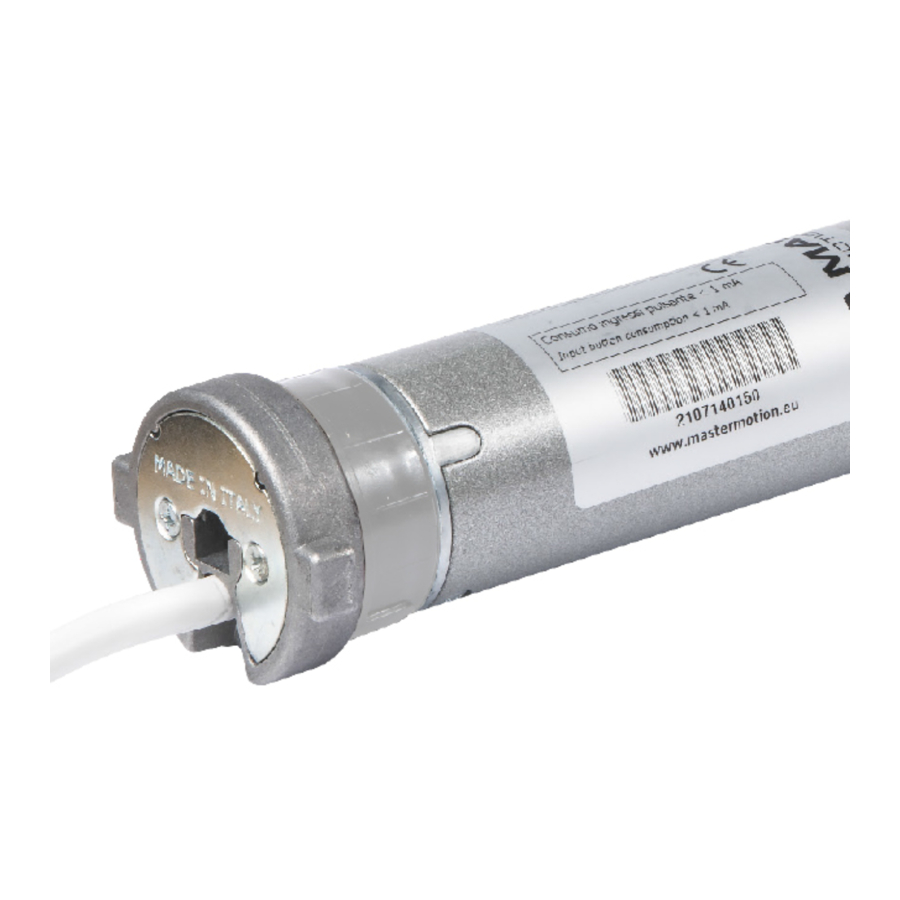
TECHNICAL SPECIFICATIONS
The technical characteristics of the motor are shown in the label applied to motor tube. Before installing the motor, it is recommended to copy the technical data (including the full name of the product) and store them in a safe place. These data may be useful in the event of subsequent maintenance or technical assistance. In addition to technical data on motor tube (depending on specific power of the motor), the common characteristics of the LINE motor family are:
Power supply : 230 Vac 50 Hz
Stand-by consumption : < 1W
Min roller diameter : 50 x 1.5 mm
Operating temperature : -20 - +50°C
IP insulation : IP44
Insulation class : H
Max limit switch revolution: 
Operating frequency : 433.42 MHz
Continuous operating time : 4 min
Memorizable transmitters : 40
Memorizable wind radio sensors : 4
Memorizable sun radio sensors : 1
ELECTRICAL CONNECTION

Warnings for the ELECTRICIAN
Make connections with power supply disconnected
- Check that the power supply does not depend from electrical circuits for lighting
- Always connect the motor to the grounding system (yellow/green)
- The supply line must be equipped with a circuit breaker. The supply line must be fitted with a device with a voltage category III, i.e. the contacts must be of 3,5 mm at least
- The product doesn't not provide any protection against overloads or short circuits. Provide the supply line with an adequate protection to the load, for example a fuse of maximum value 3,15A
- You must use buttons with spring return ("hold-to-run" type), do not use buttons with maintained position
- Command buttons are connected to the main voltage, so they must be properly insulated and protected
- The section of the connecting cables must be proportionate to their length and to the absorption of the load, and in any case not less than 1,5 mm
POWER SUPPLY
The supply voltage must be applied to the brown (PHASE) and blue (NEUTRAL) wires. Connect the green / yellow wire to the grounding system. The electrical specifications for motor operation are shown in the label applied to the tube of the motor.
COMMAND BUTTONS
The command buttons are optional. The command buttons must be connected to the black and gray wires and they must close on brown wire. You must use buttons with spring return ("hold to run" type), do not use buttons with maintained position. More command buttons can be connected via a parallel connection. The control buttons are subject to the mains voltage and therefore should be properly insulated and protected. In the case where the command buttons are not used, it is necessary to ensure the isolation of black and gray wires.
INTERFACING WITH HOME AUTOMATION CONTROL UNIT
The control outputs of the Home Automation Control Unit (following H.A.C.U.) must be connected to the command inputs of the motor (GRAY and BLACK wires), replacing the manual buttons. Consequently, the H.A.C.U. must comply with the rules of operation of the command buttons, depending on whether the command buttons work in PULSE mode (factory setting) or in HOLD TO RUN mode (see "Logic of command buttons" section).
Rules that the H.A.C.U. must comply to control the device operating with buttons in PULSE mode.
- The H.A.C.U. must not measure the current drawn by the command inputs of the device (which absorb less than 1 mA).
- The H.A.C.U. must be connected to the device as shown, substituting the command buttons with the outputs of the H.A.C.U..
- To operate the motor, the H.A.C.U. must close contact (up or down) for more than 0.5 seconds (typically using a pulse duration of 1 second).
- To stop the motor, the H.A.C.U. must close contact (up or down) for 0.5 seconds or less (typically using a pulse duration of 0.2 seconds).
Rules that the H.A.C.U. must comply to control the device operating with buttons in HOLD TO RUN mode.
- The H.A.C.U. must not measure the current drawn by the command inputs of the device (which absorb less than 1 mA).
- The H.A.C.U. must be connected to the device as shown, substituting the command buttons with the outputs of the H.A.C.U..
- To allow the conclusion of the entire opening / closing, the H.A.C.U. must be able to close the contact UP / DOWN to the time required for the motor to perform the complete operation.
- To stop the motor, the H.A.C.U. must be able to re-open the contacts UP / DOWN at any time.
At the time of this document printing, specific issues related to the connection between MASTER products and H.A.C.U. are not known (if you follow the rules above). However MASTER disclaims any responsibility concerning the non-compatibility (even partial) with any H.A.C.U.. If the H.A.C.U. uses KNX protocols or similar, contact the vendors of home automation controller informing them of the rules above. Probably the manufacturer of H.A.C.U. can provide appropriate interfaces to connect the device to the H.A.C.U..
INSTALLATION USING A TRANSMITTER
 In the case of installation of several motors, must be programmed (and therefore powered) one motor at a time.
The installation must be carried out by a qualified technician. Before starting to work on the motor, carefully read the installation procedure. In case of doubt, contact your supplier.
Installation must be performed using an ARCO, VISIO, KORT, KUADRO, FLUTE or equivalent transmitter. Before starting the installation, read the transmitter instruction manual and identify the UP, STOP, DOWN, PROG buttons necessary for motor programming.
| 1 | Connect the power supply |  | |
| 2 | Press PROG briefly (within 1 minute). The motor makes a signal |  |  |
| 3 | Press briefly UP.
|  |  |
| 4 | Bring the pergola in an intermediate position, keeping pressed UP or DOWN. |  |  |
| 5 | Press STOP briefly 3 times and wait. The motor moves downward |  |  |
| 6 | Wait automatic stop in lower limit switch |  | |
| 7 | Wait: the pergola moves upward |  | |
| 8 | Stop the motor in the desired position by pressing STOP |  |  |
| 9 | Pres PROG briefly. If you want to make a fine adjustment of the limit switch press UP or DOWN (motor moves in small steps) |  |  |
| 10 | Press PROG briefly. The motor signals DOWN-UP. End of the installation! | |  |
HOW TO MEMORIZE/DELETE A RADIO DEVICE
USING A TRANSMITTER
- Bring the motor in an intermediate position.
- Press PROG of an already memorized transmitter for 5 s. The motor performs 2 upward movements.

- Within 15 seconds, to memorize/delete: a transmitter: press STOP of transmitter you want to memorize/delete a sensor: press « P1 » of sensor you want to memorize/delete a rain sensor: press « P2 » of rain sensor you want to memorize/delete
- 1 upward movement: device memorized!!
- 1 downward movement: device deleted!!
2 downward movement: error!!

NOTES: point 03. in battery powered sensors may be necessary to keep the button pressed up to 10 seconds. point 04. "error"is reported if the radio code is not received in time, if the receiver's memory is full, if you try to delete the only memorized transmitter, if you try to memorize more than 1 sun sensor or more than 4 wind sensor.
USING COMMAND BUTTONS
- Bring the motor in lower limit switch.
- Disconnect power supply, wait a few seconds; connect power supply.
- Within 15 seconds, press DOWN 8 times (briefly and quickly). The motor performs 3 upward movements.

- Within 15 seconds, press UP 3 times (briefly and quickly). The motor performs 2 upward movements.
- Within 15 seconds, to memorize/delete: a transmitter: press STOP of transmitter you want to memorize/delete a sensor: press «P1» of sensor you want to memorize/delete a rain sensor: press «P2» of rain sensor you want to memorize/delete
- 1 upward movement: device memorized!!
1 downward movement: device deleted!!
2 downward movement: error!!

NOTES: point 05. in battery powered sensors may be necessary to keep the button pressed up to 10 seconds. point 06. "error"is reported if the radio code is not received in time, if the receiver's memory is full, if you try to delete the only memorized transmitter, if you try to memorize more than 1 sun sensor or more than 4 wind sensor.
FINE ADJUSTMENT OF UPPER LIMIT SWITCH

The modification of the upper limit switch is not possible if the upper limit switch has been learned by contact with an obstacle.
- Bring the motor to the upper limit switch.
- Disconnect power supply, wait a few seconds; connect power supply.
- Press in sequence the STOP - PROG - UP buttons(*). The motor makes 1 downward movement.

- Using UP and DOWN adjust the upper limit switch.
- Press PROG. The motor makes 1 down/up movement.
(*) briefly press, max 2 seconds between each press and the next

MODIFY BOTH THE LIMIT SWITCHES
This procedure can change the limit also if it is not completed. For this reason, in case of interruption of the procedure is necessary completely repeat the same.
- Bring the motor in an intermediate position.
- Disconnect power supply, wait a few seconds; connect power supply.
- Press in sequence the STOP - PROG - STOP buttons(*). The motor makes 1 up/down movement.

- Follow as described in "INSTALLATION USING A TRANSMITTER" section, point G and subsequent.
(*) briefly press, max 2 seconds between each press and the next

FAVORITE POSITION
| ARCO | FLUTE, KUADRO, KORT | VISIO |
| To memorize:
To recall:
| To memorize:
To recall:
| To memorize:
To recall:
|
 until the motor performs a signal
 Press
Press SUN,WIND, RAIN SENSORS
The sensors generate automatic manoeuvres without notice that can be dangerous. The installer must to inform the end-user and possibly integrate the installation with adequate security systems. In some situations (eg power loss of motor or sensor, motor failure or sensor, radio noise...) it is possible that the command imparted by the sensor is not detected by the motor. The sensor must therefore not be understood as a safety device which ensures the integrity of the roller in every condition, but a means to reduce the possibility that the shutter being damaged by adverse weather conditions.
COMPATIBLE SENSORS
The LINE series have integrated radio receiver and require the use of radio sensors. Use the sensor series BLAST or BLAST BT (wind sensor), VEGA or VEGA BT (sun/wind sensor), X11C (rain sensor) with the power supply AT12. When the sensor detects the presence of wind, the "wind alarm" command is sent: the tuned motors move upward and manual controls are disabled until the end of the alarm. When the sensor detects the presence of the sun, the "presence of sun" command is sent: the tuned motors move downward. When the sensor detects the absence of the sun, the "absence of sun" command is sent: the tuned motors move upward. When the sensor detects the presence of rain, the "presence of rain" command is sent: the tuned motors move up or down, depending on the settings of rain sensor. Each device can store up to 4 sensors wind, only one sun sensor. For more information, consult the manual of sensors.
OPERATION LOGIC OF COMMAND BUTTONS
The buttons can be operated either in PULSE logic or HOLD-TO-RUN logic.
PULSE: to activate the motor press a button for at least 0.5 seconds, to stop the motor press briefly (less than 0.5 seconds) one of the two buttons.
HOLD-TO-RUN: to activate the motor press a button for at least 0.5 seconds, to stop the motor release the button. The factory sets the device to work in PULSE logic. To modify this parameter operate as described.
ARCO
- Bring the motor in an intermediate position
- Press MENU for about 5s, until «rS» appears
- Press 1 time PREV / 8 times NEXT. «18» appears on display
- Press STOP. The motor signals:
1 UP = hold-to-run,
1 DOWN = pulse - To select PULSE: press PREVTo select HOLD-TO-RUN: press NEXT
- Press STOP. The motor signals:
1 UP = hold-to-run,
1 DOWN = pulse
FLUTE, KUADRO, KORT
- Bring the motor in an intermediate position
- Holding down STOP, press PROG for about 1 sec, until LEDs light
- Press 1 time UP / 8 times DOWN.
- Press STOP. The motor signals:
1 UP = hold-to-run,
1 DOWN = pulse - To select PULSE: press DOWN
To select HOLD-TO-RUN: press UP - Press STOP. The motor signals:
1 UP = hold-to-run,
1 DOWN = pulse
VISIO
- Bring the motor in an intermediate position
- Press MENU, «Menu rx» appears on display
- Press 17 times NEXT. «18» appears on display
- Press STOP. The motor signals:
1 UP = hold-to-run,
1 DOWN = pulse - To select PULSE: press DOWN
To select HOLD-TO-RUN: press UP - Press STOP. The motor signals:
1 UP = hold-to-run,
1 DOWN = pulse
TEST RADIO
As soon as the module stores a wind sensor, a communication control is automatically activated between the sensor and the device. If the communication is lost for more than 60 minutes, the motor performs an upward movement to protect the blind. This automatic manoeuvre is performed every 60 minutes until the reactivation of the radio communication. The factory recommends to keep the "test radio" active in order to identify in good time any malfunction of the radio sensor or of the radio communication.
ARCO
- Bring the motor in an intermediate position
- Press MENU for about 5s, until «rS» appears
- Press 1 time PREV / 7 times NEXT. «17» appears on display
- Press STOP. The motor signals:
1 UP = active,
1 DOWN = inactive - To deactivate: press PREV
To activate: press NEXT - Press STOP. The motor signals:
1 UP = active,
1 DOWN = inactive
FLUTE, KUADRO, KORT
- Bring the motor in an intermediate position
- Holding down STOP, press PROG for about 1s, until LEDs light
- Press 1 time UP / 7 times DOWN.
- Press STOP. The motor signals:
1 UP = active,
1 DOWN = inactive - To deactivate: press DOWN
To activate: press UP - Press STOP. The motor signals:
1 UP = active,
1 DOWN = inactive
VISIO
- Bring the motor in an intermediate position
- Press MENU, «Menu rx» appears on display
- Press 16 times NEXT. «17» appears on display
- Press STOP. The motor signals:
1 UP = active,
1 DOWN = inactive - To deactivate: press DOWN
To activate: press UP - Press STOP. The motor signals:
1 UP = active,
1 DOWN = inactive
TENSIONING ADJUSTMENT
During the installation, the motor calculates the optimum torque value needed to properly stretch the fabric when this is completely unrolled. The value set by the factory is: 1 MINIMUM TENSIONING. In case you want to change this parameter, operate as described.
| N° of movements | Setting |
| 1 | Minimum tensioning |
| 2 | Medium tensioning |
| 3 | Maximum tensioning |
ARCO
- Bring the motor in an intermediate position
- Press MENU for about 5s, until «rS» appears
- Press 9 times NEXT. «09» appears on display
- Press STOP. The motor signals the current value (1 to 3 movements)
- Press NEXT the number of times equal to the desired setting (1 to 3)
- Press STOP. The motor signals the new value (1 to 3 movements)
FLUTE, KUADRO, KORT
- Bring the motor in an intermediate position
- Holding down STOP, press PROG for about 1s, until LEDs light
- Press 9 times DOWN.
- Press STOP. The motor signals the current value (1 to 3 movements)
- Press DOWN the number of times equal to the desired setting (1 to 3)
- Press STOP. The motor signals the newt value(1 to 3 movements)
VISIO
- Bring the motor in an intermediate position
- Press MENU, «Menu rx» appears on display
- Press 9 times NEXT. «09» appears on display
- Press STOP. The motor signals the current value (1 to 3 movements)
- Press UP the number of times equal to the desired setting (1 to 3)
- Press STOP. The motor signals the new value (1 to 3 movements)
RESET
USING A TRANSMITTER
ARCO
- Bring the motor in an intermediate position.
- Press MENU for about 5 sec, until «rS» appears
- Press 2 time PREV / 9 times NEXT. «29» appears on display
- Press STOP. The display flashes, the motor performs some movement
- Press together PREV and NEXT for about 2 seconds until the motor indicates that the reset was performed (1 moving up / down).
- Reinstall the motor (see "INSTALLATION USING A TRANSMITTER" section).
FLUTE, KUADRO, KORT
- Bring the motor in an intermediate position.
- Holding down STOP, press PROG for about 1 sec, until LEDs light
- Press 2 time UP / 9 times DOWN.
- Press STOP. The LEDs flash, the motor performs some movement
- Press together UP and DOWN for about 2 seconds until the motor indicates that the reset was performed (1 moving up / down).
- Reinstall the motor (see "INSTALLATION USING A TRANSMITTER" section).
VISIO
- Bring the motor in an intermediate position.
- Press MENU, «Menu rx» appears on display
- Press 3 time PREV. «29» appears on display
- Press STOP. The display flashes, the motor performs some movement
- Press together PREV and NEXT for about 2 seconds until the motor indicates that the reset was performed (1 moving up / down).
- Reinstall the motor (see "INSTALLATION USING A TRANSMITTER" section).
USING COMMAND BUTTONS

- If possible, bring the motor to the intermediate position.
- Disconnect the power supply.
- Connect as on the diagram.
- Connect the power supply. Wait 30 seconds, the motor makes a signal: «Radio code deleted».
If you want to delete also the limit switch wait, otherwise go to point 6. - After 15 seconds, the motor makes another signal: «Limit switch deleted».
- Disconnect the power supply.
- Restore the connections (see diagram on "ELECTRICAL CONNECTION" section).
- Reinstall the motor (see "INSTALLATION USING A TRANSMITTER" section).
WARNINGS
Safety warnings for the USER
Incorrect installation can cause serious injuries
- Keep these instructions for future maintenance work and disposal of the product
- All the product installation, connection, programming and maintenance operations must be carried out only by a qualified and skilled technician, who must comply with laws, provisions, local regulations and the instructions given in this manual
- The wiring must comply with current IEC standards. The final electrical system must be created only by the electrician
- Some applications require hold-to-run operation and can exclude the use of radio controls or require particular safety devices
- To prevent potentially dangerous situations, check the operating condition of the roller shutter/awning regularly
Safety warnings for the INSTALLER
Before installing the product, check the compatibility with the associated devices and accessories
- Check that the package is intact and has not been damaged in transit
- A heavy knock and the use of unsuitable tools can cause the damage of the external or internal parts of the motor
- Do not pierce or tamper with the motor in any way. Do not modify or replace parts without the manufacturer's permission
- Do not carry the motor by the power cable. The product may not be used if the power cable is damaged. Do not try to replace the power cable
- Any screws needed to complete the installation must not come into contact with the motor
- The power of the motor must be sufficient for the applied load (check the rated data shown on the motor)
- Some stages of programming and/or normal operation make use of the mechanical stops of the roller shutter/awning. It is essential to choose a motor with the most suitable torque for the application, considering the actual traction of the roller shutter/awning, and to avoid motors that are too powerful
- Use winding rollers that are at least 1mm thick Leave 1-2 mm of right/left play on the winding roller
- Check that the shape and size of the drive pulley and adapter crown correspond to the winding roller used. Adapters, supports and sundry accessories related to the motor must be chosen exclusively from the MASTER catalogue.
- If the product is installed at a height of less than 2.5 m from the floor or from another support surface, the moving parts must be protected with a cover to prevent accidental access. In any case, ensure access for maintenance work
- The power cable must be positioned in such a way that it does not come into contact with moving parts
- The power cable of the product is suitable for indoor installation only. If installed outside, place the cable in a protective tube
- If there are several radio appliances in the same system, they must not be less than 1,5m apart
- Do not install the product near metal surfaces
- Position the buttons within sight of the roller shutter/awning but a long way from its moving parts. Position the buttons more than 1.5 m from the floor
- The motors are designed for residential use; the maximum continuous operating time is 4 minutes
- During operation, the motor body becomes very hot, so be careful
- The motor contains a self-resetting thermal cut-out, which stops the motor if it overheats. The motor returns to normal operation when its temperature drops below the safety limit (normally after 5 to 10 minutes)
- The motor must be installed so that it cannot come into contact with liquids and in any case in a position protected from atmospheric agents
- The antenna cable carries line voltage. Do not cut the antenna cable as this would be dangerous. If the antenna cable is damaged, replace the product
- For your safety, do not work near the winding roller while the motor is powered
Warnings for USE

The product is not intended to be used by persons (including children) with reduced physical, sensory or mental capabilities, or lack of experience and knowledge, unless they are supervised or given instructions about the product way of use by a person responsible for their safety
- Check the automation during the movement and keep people at a safe distance, until the movement ends
- Do not allow children to play with the appliance or with the fixed control devices
- Do not operate the blind when maintenance operations are being carried out (e.g.windowcleaning, etc.). If the control device is automatic, disconnect the motor from the power line


Documents / ResourcesDownload manual
Here you can download full pdf version of manual, it may contain additional safety instructions, warranty information, FCC rules, etc.
Advertisement


Need help?
Do you have a question about the LINE and is the answer not in the manual?
Questions and answers