Aiphone LEF Series, LEF-3, LEF-5, LEF-10, LEF-10S Manual
- Installation & operation manual (16 pages) ,
- Instructions manual (16 pages) ,
- Installation manual (9 pages)
Advertisement
- 1 SYSTEM OUTLINE & COMPONENTS
- 2 NAMES & FEATURES
- 3 WIRING
- 4 MOUNTING
-
5
OPERATIONS
- 5.1 Calling a master or sub
- 5.2 Receiving a call from a sub station
- 5.3 Receiving a call from another master
- 5.4 Door answering
- 5.5 Door strike w/LOCK
- 5.6 All Call with ALL CALL button
- 5.7 BG-10C All Call/Chime and Music Adaptor
- 5.8 Privacy feature
- 5.9 LE sub stations
- 5.10 When called by a sub station while talking to another station
- 6 TROUBLESHOOTING GUIDE
- 7 TECHNICAL PRECAUTIONS
- 8 SPECIFICATIONS
- 9 PRECAUTIONS ON INSTALLATION & WIRING
- 10 Documents / Resources
SYSTEM OUTLINE & COMPONENTS
System outline
LEF is a flexible Open Voice Selective Call Intercom system, which integrates any combination of master and sub stations, Selective calling from any master, with handsfree reply. Incorporates a variety of additional features as described below.

Package contents
- LEF intercom (LEF-3, 5,10 or 10S)
- Packet of screws
- Installaiton & Operation Manual
Components available
- Intercoms: Masters or subs, intermixable
![]()
- Sub stations:
LE-DL: Surface-mount w/anodized aluminum panel
★ 8H horn speaker w/LT-1 matching transformer - All Call & music:
BG-10C: All call, chime & music adaptor.
Requires a PS-12F power supply (12V DC, 2.5A). - PanTilt door stations:
MYW-P1L or MYW-P3L adaptor: For 1 or 3 PanTilt doors. Includes one or two MYH-CU monitors. Max. 3 monitors with add'| PS-18C or PS-18D.
MY-DC/A, MY-DG/A w/full PanTilt capability.
MY-CA, MY-FA, with prism lens for PanTilt.
MY-DS, wide angle and longer distance.
MYW-CA overhead enclosure w/MY-CA installed, with IE/IF audio door for communication.
![]()


NAMES & FEATURES
Names & functions

LEF-3
- Speaker
- Call-in LED (3)
- Station-Select button (3)
- Voice volume control
- OFF button (WON LED)
- Mic
- Occupied LED (In-use)
- Priv. button & LED indicator
- Talk (listen) button

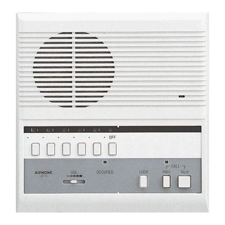
LEF-5,10, 10S
- Speaker
- Call-in LED (5 or 10)
- Station-Select button (5 or 10)
- Voice volume control
- Occupied (In-use) LED
- All Call transmit button & LED
- Door Strike button
- Mic. (initiator only)
- OFF button (WON LED)
- Priv. button & LED indicator
- Talk (listen) button
★ LEF-5: 5 station buttons and OFF.
LEF-10: All Call button & LED not included
Features


- Four LEF master stations, intermixable.
| Models | Capacity | Door strike | All Call transmit | PanTilt door |
| LEF-3 | 4 stations | |||
| LEF-5 | 6 stations | x | x | |
| LEF-10 | 1 1 stations | x | x | |
| LEF-10S | 1 1 stations | x | x | x |
- Loop-wired system with multiconductor shielded cable.
All-master system: 5 common wires + total No. of stations in the system.
If All Call is included: Add 3 additional common wires (P1-P3).
If Door Release is included (LEF-5/10/10S): Add 1 common (L) + 1 individual wire for each door to be released (K# terminals).
Single-master system: 2 wires homerun from each sub to the master. Leave jumpers between E & - installed.
Intermixed system with masters and subs: 3 wires from each sub to the nearest master, or 2 common + 1 individual wire per station on a loop. Remove jumpers between E & - from all stations in a multi-master system. - Optional features:
- 1 or 3 PanTilt doors (w/ MYW-P1L or MYW-P3L adaptor)
- All Call, chime & Music distribution (w/BG-10C adaptor)
- Door strike EL-9S (w/RY-PA relay)
- 8Ω horn speaker (w/LT-1 transformer)
- External signalling when door/sub calls (w/RY-AC/A and external device)
WIRING
* LEW-5, LEW-10, and LEW-10S Terminal boxes are not equipped with K1 ~ K5, K1 ~ K10 terminals.


* Shorting link on E and - terminal: Must remain attached in a single-master system. Remove when 2 or more masters are in a system.
Terminal definitions
| 1 ~ 10: | Station number, establishes communication to other LEF masters (to "C" terminal) or LE subs (to "1" terminal) |
| E: | Common communication line |
| C: | "CALL", Call receive from another master (and All Call/Chinne/Music reception) |
| R: | Activates occupied LED to indicate when any master is ON (line drops to 0V DC when any master is on.) |
| Y: | Occupied mode control during All Call (becomes +9V DC during All Call) |
| L: | Door strike activation (becomes +12V DC when "key" button is pressed) |
| +, | 12V DC power supply connection |
| PI: | All Call control (becomes +10V DC when All Call button is pressed and activates pretone) |
| P2, P3: | All Call transmit audio path from initiating master to BG-10C |
★ K1 - K5 (LEF-5), K1 - K10 (LEF10,10S): Selective control terminal, used for video control with MY PanTilt series, or for selective door release (w/RY-PA) from the master to multiple doors. ("K#" terminal becomes ground (-) when corresponding station number is pressed.)
Call tone adjustment

3-position adjustment switch, located under directory cover plate.
Selector switch for intermixing with LAF models
If intermixing LEF with LAF models (except LAF-B), change setting from B to A position on all LEF models.
* If a call tone is desired when a sub station calls in and the system is occupied, change the switch on the LEF masters to the A position.
"A" pos.: Mutes call tone at master while system is in occupied mode.
"B" pos.: Call tone is heard when master is in occupied mode.

LEF all-master configurations
LEF all-master systems are designed to be wired in a looped fashion from the first to last master. Number of conductors for a full system (not including "K" terminals) are:
| Model | Cable | Wire number |
| LEF-3 | 9 conductors | #822210 in USA |
| LEF-5 | 1 2 conductors | #822212 in USA |
| LEF-10 | 1 7 conductors | #822220 in USA |
| LEF-10S | 20 conductors | #822220 in USA |
| LE Subs | 3 conductors | #822203 or #821803 in USA |
- Single-master system can be wired with 2 conductors homerun from each sub. (Wire #822202 or #821802 in USA)
Cable requirements
Use multi-conductor cable with an overall shield, non-twisted, 22AWG to 18AWG (0.65mm to 1.0mm), to accommodate the maximum number of LEF master stations, LE subs, audio or PanTilt door(s), or 8Q paging zones, each of which requires one designated wire.
Power supply
Entire LEF system can be powered by one PS-12C (or PS-12A) power supply, located near the center of the trunkage cable. For a system including All-Call, Chime, & Music with the BG-10C, use a PS-12F power supply (12V DC, 2.5A) to power the entire system.
Wiring diagrams
- LEF-3 with 2 subs, 1 Door, LEF-3 and External Signalling


★ Shorting link on E - – terminals must remain attached on all units.
 : PS-12C or PS-12A
- Two LEF-3 and 2 Doors


★ Shorting link E - – terminals is removed on all units.
: PS-12C or PS-12A
- LEF-5 All Master System


: PS-12C or PS-12A
★ Shorting link is removed on all LEF-5's.
- LEF-5 with Selective Door Release


: PS-12C or PS-12A
 : PT-1210N in USA or AC trans.
★ Shorting link is attached on all units.
- LEF-10 with LE-A3 sub stations


★ Shorting link is removed on all units.
: PS-12A or PS-12C
- LEF-10S Intermixed System with Ali Call and Door Chime


Capacitor: NP-25V in USA
★ Shorting link is removed on all units.
 : PS-12F, 12VDC, 2.5A
- LEF-5 w/8 ohm horn (AH-108 in USA)


Capacitor: NP-25V in USA
★ Shorting link on E - – is removed on all units.
: PS-12C or PS-12A
MOUNTING
- LEF-3
![]()
- LEF-5, 10, 10S

- LE room subs
![]()


★ 1,2: When running cable on surface, pass cable through top or bottom section, and fasten with a clamp (attached).
★ Slide LE unit until it locks with the prongs.
Wall-mounting
- Remove the directory card by pressing down on one side and lifting off from the middle.
- Loosen the two screws. (Do not remove screws from front case.)
- Disconnect LEF intercom from the chassis by unplugging connectors.
- Mount the back chassis to a single-gang box.
- Terminate wires on screw terminals inside the chassis.
- Reconnect intercom with connectors and mount to chassis.
Wall surface-mounting or desk use

- Plug in CN-1 & CN-2 connectors of LEW-5, LEW-10, or LEW-10S to muiti-pin sockets inside LEF master (Connectors from chassis disconnected). Use clamps on LEF back case to secure cable.
- Install the terminal box in a convenient place with the field wiring connected to it. The cord from the box to the LEF unit is approx. 7'7" long.
OPERATIONS
★ LEF is a single talkpath system. While the Occupied LED is lit, do not attempt to select a station or initiate an All Call.
★ If called by a master and sub at the same time, reply to the master's call handsfree first. When the Occupied LED goes off, select the sub station that called.


★ LEF-10S only
Calling a master or sub
- Depress a station selector button 1 ~ 10.
- Press the TALK button to speak, and release to listen to the reply.
- If you wish to ring a tone as an attention-getter, press the PRIV (privacy) and TALK buttons together, then hold the TALK button down while speaking.
- To conclude, depress OFF button.
Receiving a call from a sub station
- Sub station calls in with tone and LED, which stays lit for 20 seconds.
- Depress the lit station selector button.
- Press the TALK button to speak, and release to listen.
- Depress OFF button when finished.
Receiving a call from another master
- When a master calls to another master, no station LEDs light up, and the responding master answers back handsfree.
- The Occupied lamp will be on while the initiating master has a station selected.
- Do not press any buttons on the master when responding to another master's call. If the privacy feature is engaged, press TALK button momentarily to release before responding.
Door answering
(From a master station only):
- LE-D/DA audio door station calls in with tone & LED, which stays lit for 20 seconds.
When PanTilt MY door station calls in, MYFI-CU monitor turns on, and will stay on for approx. 45 seconds. - Depress the lit selector button, then press TALK to speak, release to listen.
Door strike w/LOCK
LEF-5, LEF-10, and LEF-10S provide selective door release to multiple doors (RY-PA for each). When communication is established to a door station, press the "KEY" button to release the door.
All Call with ALL CALL button
On LEF-10S station only, ALL CALL feature allows an announcement to be made to all the stations in the system. The BG- 10C is required to make this feature operable.
- Press ALL CALL button.
- Press TALK to make an announcement.
- Press ALL CALL button again to release.
BG-10C All Call/Chime and Music Adaptor
Music is selectively distributed to all LEF station speakers, controlled by switch settings.
When any station initiates a call, the music mutes automatically.
When door station calls in, chime tone is transmitted to selected LEF stations, controlled by switch settings.
Privacy feature
When PRIV button is depressed, the calling master can call into a station in "privacy" mode, but the "listen" mode is cut off.
To release from PRIV, press TALK momentarily.
LE sub stations
To call a master station:
- Simply press the CALL button, which rings an electronic tone (for as long as button is held). The corresponding LED will be lit for 20 seconds.
- When master replies, speak handsfree.
- LE-A3 and LE-AN3 can call selectively to up to 3 LEF master stations.
When called by a sub station while talking to another station
The station's LED will light for 20 sec., but call tone is muted. Depress OFF button to disconnect from original call, the depress the selector button with lit LED.
TROUBLESHOOTING GUIDE
| Problem | Solution | |
| Single-master system |
| Make sure jumper is installed between E and - at the subs and the master station. |
| Same as #1, E & - jumper must be in place. If 3 wires are used, 1 & - are for call-in, and 1 & E are for communication. Check continuity and connection of wires. | |
| Multi-master system |
| The "C" terminal of the master means "CALL", and allows master-to-master communication. Make sure the "C" terminal of each master is connected to a designated # terminal on all other masters, (example: C at master 1 connects to the "1" teminal of all other masters.) |
| Adjust call tone volume with slide switch located under faceplate. (Use small screwdriver.) | |
| Station LEDs only light when a sub station calls. A responding master answers handsfree, therefore not having to select a station number. | |
| Make sure all masters are in the OFF (standby) position. The station whose LED above the OFF button is lit is the one that's on. Check "R" wire for a short to ground. Take R wire off of unit. If Occupied light remains lit, the unit is damaged and needs repair. | |
| Check E and - wires from sub for proper connection to master. See # 2 solution above. | |
| Make sure station number wires are not shorted together. Remove all jumpers between E & -. Test master station by taking wires off of affected station #'s, then touch a jumper wire between a station number and negative. If multiple LEDs light up, the unit has sustained power surge damage and must be sent in for repair. | |
| RY-PA relay is required for each door to be released. Connect black wires to L & -. For selective door release, connect RY-PA between K#(matching station # that door is on) and L, L which provides 12V DC when "key" button is pressed. | |
| All Call requires the BG-10C Adaptor with PS-12F power supply. | |
| BG-10C must be installed. Wire from door station must connect to BG-10C, "1" of door to DA/DB/DC of BG-10C. Neg. (-) must be connected from LEF to BG-10C. | |
| Door station should be wired directly to BG-10C or first master. Make sure the A/B switch on the back of the LEF master is in the "A" position. Make sure "R" line is connected between LEF master and BG-10C. | |
| Check connection from P1, P2, P3 terminals from LEF-10S to BG-10C. P1 should be 10V DC or higher when All Call button is engaged. P2 and P3 carry the voice signal from the initiating master to the BG-1 DC. Be sure to press TALK while making an All Call announcement, and press All Call button when finished. | |
| Adjust volume levels on front panel of BG-10C. | |
| Make sure jumpers between E & - are removed. When using the BG-10C for All Call in a system with sub stations, a non polarized capacitor (NP-25V) must be installed in series on each station # line that a sub staiton is on between the BG-10C and LEF-10S. | |
| Intercom stations should not be mounted back to back on the same wall. If isolating them. Adjust voice volume control downward to eliminate feedback. | |
| Adjust "Voice Vol." upward. Make sure the "1 and -" terminals from sub to master are not reversed. | |
| System wiring must be run at least 20", 50cm away from AC wiring fluorescent lights, or dimmer switches. Wires can cross AC at 90 degrees. If shielded wire was used, tie all of the shields together and ground one end to an earth ground, if noise persists, isolate source of the noise and separate the intercom from the source. |
TECHNICAL PRECAUTIONS

- Aiphone Corporation is not responsible for improper installations of its product which result in interference generated by dimmer switches, fluorescent lighting fixtures or other similar electrical devices. Any such installation must be corrected at the source by the installing party. Aiphone also recommends that when installing any of its communication products that the intercom wiring be run at least 20 inches (50 cm) away from any AC wiring.
- In LEF/MY video system, run a separate LEF audio cable and MY video cable. Using the same cable for both audio and video systems will cause severe interference with the LEF audio communications.
- Clean your LEF equipment with a soft cloth dampened with neutral household cleanser. Never use any abrasive cleaner or cloth,
SPECIFICATIONS
| Power source: | 12V DC, 300mA per station. Use a PS-12A or PS-12C or PS-12F power supply, 1 per system. | |||||
| Communication: | Press-to-talk, release-to-listen at master station. ★ Master-to-master calling does not turn on station LED. | |||||
| Talk channel: | 1 channel. Occupied LED is lit when system is in use. | |||||
| Output: | 800mW at 20Q (reception). 500mW at 20Q (transmission). | |||||
| Wiring: |
| |||||
| Key-mark button contact: | 30V DC, 0.1 A (resistance load). | |||||
| Select switch contact: | 12V DC, 30mA (for external device control). | |||||
| Wiring distance: | 0.65mmØ | 0.8mmØ | 1.0mmØ | 22AWG | 20AWG | 18AWG |
| 200m | 300m | 480m | 650' | 1,000' | 1600' | |
| Dimensions & weight: | ||||||
| LEF-3: | 180 H x 143 W x 55 D (mm). 7-1/16" H x 5-5/8" W x 2-3/16" D. 420g, 0.93 lbs. approx. | |||||
| LEF-5, 10, 10S: | 206 H x 190 W x 55 D (mm). 8-1/8" H x 7-1/2" W x 2-3/16" D. 550g, 1.21 lbs. (LEF-5). 650g, 1.43 lbs. (LEF-10, 10S). | |||||
PRECAUTIONS ON INSTALLATION & WIRING

- Do not connect AC wires to any terminal on any unit, as fire or unit damage may occur. Connect only the specified power source on +, - terminals.
![]()
- Do not install more than one power supply (PS-12C or PS-12F or PS-12A) for an entire LEF system.
- Do not attempt to install or connect wires on LEF equipment while system's power supply is plugged in.
- LEF masters and related equipment, except door station, are designed for indoor use only. Do not install outdoors.
- There is no need to disassemble the equipment for installation, other than to open the unit to connect the wires to the back case. Do not access the PC board or components unless properly qualified.
- Any other manufacturer's products installed with this system (power supply, external signalling device, etc.) are not covered under Aiphone's warranty.
- Do not mount LEF equipment in the following places, as it may cause the system to malfunction:
- High or extreme cold temperature areas: under direct sunlight, near equipment that varies in temperature, in front of air conditioner, inside a refrigerated area, etc.
- Places subject to moisture or humidity extremes.
- Places subject to environmental conditions, such as dust, oil, chemicals, salt, etc.
- LEF units are electronic devices, which must not be subjected to water or any other liquid.
- Severe weather conditions, such as lightning storms, may cause damage to LEF equipment.
We recommend that power surge protection be installed as follows: (However, this does not guarantee that no damage will occur).- If the power supply has a GROUND terminal, take it to an earth ground. In this case, a separate surge arrester is not necessary.
- When using a power supply that has no GROUND terminal, install a surge arrester near the output as shown.
- Additional SA-1 surge arresters can be installed to protect communication lines. One SA-1 per: 2 wires on master station.

Install a surge-arrester (discharging voltage: 100-180V) at a point close to the output, taken to earth ground.
- Before actually installing the LEF system, the contents in the "Wiring" section must be thoroughly read and understood.
Aiphone Co., Ltd., Nagoya, Japan
Aiphone Corporation, Bellevue, WA, USA
Documents / ResourcesDownload manual
Here you can download full pdf version of manual, it may contain additional safety instructions, warranty information, FCC rules, etc.
Download Aiphone LEF Series, LEF-3, LEF-5, LEF-10, LEF-10S Manual
Advertisement


Need help?
Do you have a question about the LEF Series and is the answer not in the manual?
Questions and answers