
Related Manuals for HP Enterprise ProLiant DL20 Gen11


Summary of Contents for HP Enterprise ProLiant DL20 Gen11
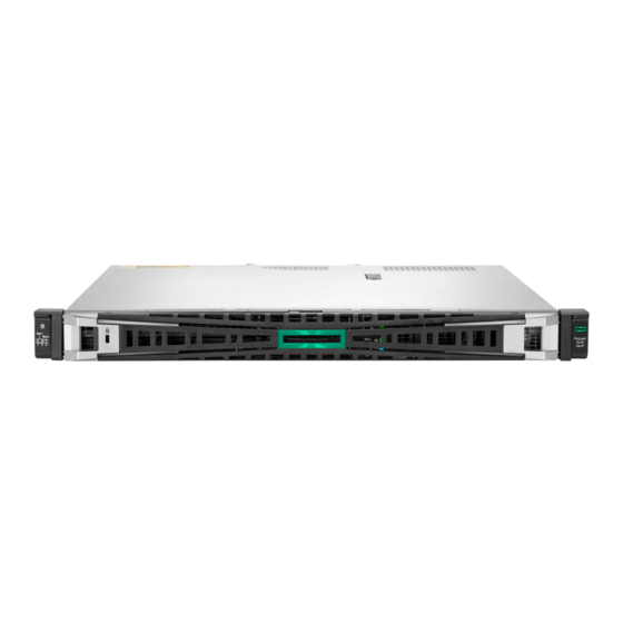
- Page 1 HPE ProLiant DL20 Gen11 Server User Guide HPE ProLiant DL20 Gen11 Server User Guide Part Number: 30-1A938BDF-002 Published: May 2024 Edition: 2...
- Page 2 HPE ProLiant DL20 Gen11 Server User Guide HPE ProLiant DL20 Gen11 Server User Guide Abstract Abstract This document is for the person who installs, administers, and troubleshoots servers and storage systems. Hewlett Packard Enterprise assumes you are qualified in the servicing of computer equipment and trained in recognizing hazards in products with hazardous energy levels, and are familiar with the weight and stability precautions for rack installations.
- Page 3 Table of contents Table of contents Component identification Front panel components iLO Service Port Front panel LEDs and buttons Server UID LED Using the UID button to view the Server Health Summary Front panel LED power fault codes Rear panel components Display device setup Rear panel LEDs System board components...
- Page 4 Server warnings and cautions Electrostatic discharge Operations Remove the front bezel Power down the server Extend the server out of the rack Remove the server from the rack Remove the access panel Remove the riser cage Install the riser cage Install the access panel Install the server into the rack Power up the server...
- Page 5 Installing an optical drive in the LFF drive chassis Installing an optical drive in the SFF drive chassis Memory option DIMM population information DIMM installation guidelines Installing a DIMM PCIe riser option Installing a riser option Storage controller options Preparing the server for storage controller installation Installing the type-o storage controller Installing the type-p controller option Energy pack option...
- Page 6 Energy pack cabling Storage controller backup power cabling Optical drive cabling HPE NS204i-u Boot Device cabling External OCP enablement cabling Fan cabling Cable routing in front of the PCIe fan Chassis intrusion detection switch cabling Serial port cabling Front I/O cabling System power cabling Non-hot-plug power supply cabling Configuration resources...
- Page 7 HPE 800 W Flex Slot Titanium Hot-plug Low Halogen Power Supply HPE 1000 W Flex Slot Titanium Hot-plug Power Supply Websites Support and other resources Accessing Hewlett Packard Enterprise Support HPE product registration Accessing updates Customer self repair Remote support Documentation feedback...
-
Page 8: Component Identification
Component identification Component identification This chapter describes the external and internal server features and components. Subtopics Subtopics Front panel components Front panel components Front panel LEDs and buttons Front panel LEDs and buttons Rear panel components Rear panel components Rear panel LEDs Rear panel LEDs System board components System board components... - Page 9 Item Item Description Description Optical drive (optional) Serial number/iLO information pull tab iLO service port HPE NS204i-u Boot Device (optional) USB 3.2 Gen1 port 2 LFF non-hot-plug drive cage The serial number/iLO information pull tab is double-sided. One side shows the server serial number and the customer asset tag label. The other side shows the default iLO account information.
- Page 10 Item Item Description Description Media bay Optical drive (optional) 2 SFF hot-plug drive cage (optional) Serial number/iLO information pull tab iLO service port HPE NS204i-u Boot Device (optional) USB 3.2 Gen1 port 4 SFF hot-plug drives The media bay supports the optical drive cage or the 2 SFF drive cage option. The 2 SFF drive cage supports SAS, SATA, or U.3 NVMe drives .
-
Page 11: Front Panel Leds And Buttons
You cannot access the server by connecting to the Service Port. You cannot access the connected device from the server. For more information about the iLO Service Port, see the iLO user guide at the following website: https://www.hpe.com/support/ilo6 https://www.hpe.com/support/ilo6. Front panel LEDs and buttons Front panel LEDs and buttons Item Item... -
Page 12: Front Panel Led Power Fault Codes
Using the UID button to view the Server Health Summary Using the UID button to view the Server Health Summary Front panel LED power fault codes Front panel LED power fault codes Server UID LED Server UID LED The UID LED is used to locate a particular server when it is deployed in a dense rack with other equipment. Activating the UID LED helps an on-site technician to quickly identify a server for maintenance tasks. -
Page 13: Rear Panel Components
Subsystem Subsystem LED behavior LED behavior System board 1 flash Processor 2 flashes Memory 3 flashes Riser board PCIe slots 4 flashes FlexibleLOM 5 flashes Storage controller 6 flashes System board PCIe slots 7 flashes Power backplane 8 flashes Storage backplane 9 flashes Power supply 10 flashes... -
Page 14: Rear Panel Leds
Item Item Description Description NIC 1 / iLO shared port (1 GbE) NIC port 2 (1 GbE) NIC port 3 (1 GbE) Serial port (optional) Slot 1 PCIe5 x16 (16, 8, 4, 1) ATX non-hot-plug power supply Flexible Slot power supply 1 Flexible Slot power supply 2 (optional) OCP 15 PCIe5 x4 iLO dedicated network port (optional) -
Page 15: System Board Components
Item Item Status Status Definition Definition NIC/iLO link Solid green Network link speed is 1000 Mb/s. Solid amber Network link speed is 10/100 Mb/s. No network link NIC/iLO activity Flashing green Network active No network activity Power supply Solid green The power supply is operating normally One or more of the following conditions exists: Power is unavailable... - Page 16 The system board comprises of three individual printed circuit assemblies (PCA): Item Item Board Board Mainboard Pass-through board (PTB) Power distribution board (PDB) The PTB is connected to Slot 14 internal OCP PCIe4 x4. The Slot 15 external OCP PCIe4 x4 is accessible from the rear panel. HPE ProLiant DL20 Gen11 Server User Guide...
-
Page 17: System Maintenance Switch Descriptions
Item Item Description Description 4-pin processor power connector Storage controller backup power connector Chassis intrusion detection switch connector SlimSAS x8 port 1 Front I/O & USB 3.2 Gen 1 & iLO service port connector SlimSAS x8 port 3 Energy pack connector SlimSAS x4 port 2 Stacked, internal dual USB 3.2 Gen 2 ports 4-pin processor power connector... -
Page 18: Dimm Label Identification
Position Position Default Default Function Function Off—iLO 6 security is enabled. On—iLO 6 security is disabled. Reserved Reserved Reserved Off—Power-on password is enabled. On—Power-on password is disabled. 1 , 2 , 3 Off—No function On—Restore default manufacturing settings Reserved Reserved Reserved Reserved Reserved... -
Page 19: Dimm Slot Numbering
Item Item Description Description Example Example Capacity 16 GB 32 GB 64 GB 128 GB 256 GB Rank 1R—Single rank 2R—Dual rank 4R—Quad rank 8R—Octal rank Data width on DRAM x4—4-bit x8—8-bit Memory generation PC5—DDR5 Maximum memory speed 4800 MT/s 5600 MT/s CAS latency B—42-42-42... - Page 20 Riser board component Riser board component Slot number Slot number Slot type Slot type Slot power Slot power Supported form factors Supported form factors PCIe5 x16 (16, 8, 4, 1) 75 W Full-height, half-length Half-height, half-length (low-profile) OCP slot population rules OCP slot population rules HPE ProLiant DL20 Gen11 Server User Guide...
- Page 21 Item Item Slot number and description Slot number and description Supported expansion options Supported expansion options Slot 14 OCP PCIe5 x4 (internal OCP) Type-o storage controller Slot 15 OCP PCIe5 x4 (external OCP) OCP NIC 3.0 adapter PCIe5 slot description PCIe5 slot description HPE ProLiant DL20 Gen11 Server User Guide...
- Page 22 Item Item Description Description Definition Definition PCI Express version Each PCIe version corresponds to a specific data transfer rate between the processor and peripheral devices. Generally, a version update corresponds to an increase in transfer rate. PCIe 1.x PCIe 2.x PCIe 3.x PCIe 4.x PCIe 5.x...
-
Page 23: Drive Bay Numbering
The SFF basic drive carrier supports hot-plug SAS, SATA, or U.3 NVMe drives . Item Item State State Definition Definition Fault/Locate Solid amber This drive has failed, is unsupported, or is invalid. Solid blue The drive is operating normally and being identified by a management application. - Page 24 Onboard connection for the Intel VROC SATA RAID support is through the SlimSAS x4 port 2. 2 LFF hot-plug drive bay numbering 2 LFF hot-plug drive bay numbering The 2 LFF hot-plug drive box uses the 2 LFF 12G x1 SAS UBM3 LP BP drive backplane. For more information on the drive backplane description, see Drive backplane naming.
- Page 25 guides: Drive backplane support, see Drive bay numbering. Drive backplane cabling, see Storage cabling. Item Item Description Description Values Values Drive bay count Number of drive bays supported by the backplane. Drive form factor LFF—Large Form Factor SFF—Small Form Factor E3.S—Enterprise and Datacenter Standard Form Factor (EDSFF) Maximum link rate per lane (GT/s) Port link width and interface...
-
Page 26: Fan Numbering
Item Item Description Description Module stabilizer iLO dedicated network port Serial port cable connector Standoff for the M.2 22110 SSD Standoff for the M.2 2280 SSD Standoff for the M.2 2242 SSD M.2 slot Not for use in this server Fan numbering Fan numbering HPE ProLiant DL20 Gen11 Server User Guide... -
Page 27: Fan Mode Behavior
Fan number Description Fan number Description Processor fan System fan PCIe fan Fan mode behavior Fan mode behavior The server supports nonredundant fan mode. If a fan fails or is missing, the following behaviors are exhibited: The health LED flashes red. The operating system performs a graceful shutdown. - Page 28 When the embedded TPM is enabled, the Trusted Platform Module operates in TPM 2.0 mode. Use the UEFI System Utilities to configure the TPM. From the System Utilities screen, select System Configuration > BIOS/Platform Configuration (RBSU) > Server Security > Trusted Platform Module options. For more information, see the UEFI user guide: https://www.hpe.com/support/UEFIGen11-UG-en https://www.hpe.com/support/UEFIGen11-UG-en When using the Microsoft Windows BitLocker Drive Encryption feature, always retain the recovery key or password.
- Page 29 Item Description Item Description Boot device cage M.2 slots Boot device carriers HPE NS204i-u Boot Device LED definitions HPE NS204i-u Boot Device LED definitions NOTE: NOTE: The bay number can be found on the SSD carrier handle. HPE ProLiant DL20 Gen11 Server User Guide...
- Page 30 Item Item Status Status Definition Definition Fault or Locate Solid amber Drive has failed, unsupported, or invalid. Solid blue Drive is operating normally. Flashing amber or blue Drive has failed, or a predictive failure alert is received for the drive. (one flash per second) Flashing amber (one flash Drive predictive failure alert is received.
- Page 31 HPE Installation Service Installation Service HPE Installation Service provides basic installation of Hewlett Packard Enterprise branded equipment, software products, as well as HPE- supported products from other vendors that are sold by HPE or by HPE authorized resellers. The Installation Service is part of a suite of HPE deployment services that are designed to give users the peace of mind that comes from knowing that their HPE and HPE-supported products have been installed by an HPE specialist.
- Page 32 using HPE GreenLake for Compute Ops Management , see https://www.hpe.com/info/com-docs https://www.hpe.com/info/com-docs. Use the Firmware Update option in Intelligent Provisioning—Intelligent Provisioning is a server deployment tool embedded in HPE ProLiant servers. To access Intelligent Provisioning, during the server boot process, press F10 F10.
-
Page 33: Operational Requirements
If a DHCP server assigns the IP address, the IP address appears on the boot screen. If a static IP address is assigned, use that IP address. c. Enter the iLO login name and password, and then click Log In. d. -
Page 34: Temperature Requirements
warm air to escape from the cabinet. To prevent improper cooling and damage to the equipment, do not block the ventilation openings. When the vertical space in the rack is not filled by a server or rack component, the gaps between the components cause changes in airflow through the rack and across the servers. -
Page 35: Rack Warnings And Cautions
Because of the high ground-leakage currents associated with multiple servers connected to the same power source, Hewlett Packard Enterprise recommends the use of a PDU that is either permanently wired to the building’s branch circuit or includes a nondetachable cord that is wired to an industrial-style plug. -
Page 36: Server Warnings And Cautions
CAUTION: CAUTION: Before installing the server in a rack, be sure to properly scope the limitations of the rack. Before proceeding with the installation, consider the following: You must fully understand the static and dynamic load carrying capacity of the rack and be sure that it can accommodate the weight of the server. -
Page 37: Remove The Front Bezel
finger or other conductor may damage system boards or other static-sensitive devices. This type of damage may reduce the life expectancy of the system or component. To prevent electrostatic damage: Avoid hand contact by transporting and storing products in static-safe containers. Keep electrostatic-sensitive parts in their containers until they arrive at static-free workstations. -
Page 38: Power Down The Server
About this task About this task If you are using the iLO virtual power button to power the server on/off, you do not need to remove the front bezel. Remove the front bezel only if you need to access the front panel components. Procedure Procedure 1. - Page 39 Before powering down the server for any upgrade or maintenance procedures, perform a backup of critical server data and programs . IMPORTANT: IMPORTANT: When the server is in standby mode, auxiliary power is still being provided to the system. To power down the server, use one of the following methods: Press and release the Power On/Standby button.
- Page 40 WARNING: WARNING: To reduce the risk of personal injury, be careful when pressing the server rail-release latches. The inner rails could pinch your fingers. Press and hold the rear-end rail-release latches, and then slide the server out of the rack until it is fully extended. Remove the server Remove the server from the...
- Page 41 Get help to lift and stabilize the server during removal from the rack. If the If the server server is installed higher than chest level, an additional two is installed higher than chest level, an additional two people might be required to help remove the server people might be required to help remove the server: : One person to support the server weight, and the other two to slide the server out of the rack.
- Page 42 WARNING: WARNING: To reduce the risk of personal injury, be careful when pressing the server rail-release latches. The inner rails could pinch your fingers. Press and hold the rear-end rail-release latches, and then slide the server out of the rack until it is fully extended. 8.
-
Page 43: Remove The Access Panel
9. Place the server on a flat, level work surface. Remove the access panel Remove the access panel Prerequisites Prerequisites Before you perform this procedure, make sure that you have a T-15 Torx screwdriver available. About this task About this task WARNING: WARNING: To reduce the risk of personal injury from hot surfaces, allow the drives and the internal system components to cool before touching them. - Page 44 4. Remove the server from the rack. 5. Place the server on a flat, level work surface. 6. Remove the access panel: a. If necessary, unlock the access panel latch. b. To disengage the access panel from the chassis, press the release button and pull up the latch. c.
- Page 45 7. If an expansion card with internal cables is installed on the riser, disconnect the cables from the card. 8. Remove the riser cage: a. Loosen the riser cage thumbscrew. b. Lift the riser cage off the mainboard. Install the riser cage Install the riser cage Prerequisites Prerequisites...
-
Page 46: Install The Access Panel
Install the access panel Install the access panel Prerequisites Prerequisites Before you perform this procedure, make sure that you have a T-15 Torx screwdriver available. Procedure Procedure 1. With the access panel latch open, insert the guide pin on the chassis through the hole on the bottom side of the latch. 2. - Page 47 4. Perform the post-installation or maintenance steps required by the procedure that necessitates the removal of the access panel. Install the server Install the server into the into the rack rack Prerequisites Prerequisites Get help to lift and stabilize the server during rack installation. If the If the server server is installed higher than chest level, an additional two people is installed higher than chest level, an additional two people...
- Page 48 2. Open the chassis ears, and then tighten the shipping screws. 3. Connect all peripheral cables to the server. 4. Connect the power cords: a. Connect each power cord to the server. b. Connect each power cord to the power source. 5.
-
Page 49: Power Up The Server
Power up the server Power up the server Procedure Procedure Press the Power On/Standby button. Use the virtual power button through iLO 6. Hardware options installation Hardware options installation This chapter provides instructions for installing supported hardware options. To ensure proper server deployment and operation, Hewlett Packard Enterprise recommends installing only HPE‑validated hardware options. - Page 50 Transceiver option Transceiver option Pass-through board option Pass-through board option Installing the two-bay SFF drive cage option Installing the two-bay SFF drive cage option Optical drive option Optical drive option Memory option Memory option PCIe riser option PCIe riser option Storage controller options Storage controller options Energy pack option...
-
Page 51: Rack Mounting Options
For servers managed by HPE GreenLake for Compute Ops Management , make sure that you have your HPE GreenLake account ID. For more information, see HPE GreenLake for Compute Ops Management Getting Started Guide HPE GreenLake for Compute Ops Management Getting Started Guide . Hardware option installation guidelines Hardware option installation guidelines WARNING:... - Page 52 Rail identification markers Rail identification markers Rack mounting interfaces Rack mounting interfaces Rack rail option Rack rail option Installing the server into the rack: Friction rack rail Installing the server into the rack: Friction rack rail Installing the rack rail hook-and-loop strap Installing the rack rail hook-and-loop strap Installing the cable management arm Installing the cable management arm...
- Page 53 Rail identifier stamps on the mounting rail of the friction rack rail Rack mounting interfaces Rack mounting interfaces The rack rails can be installed in a rack that has the following mounting interfaces: Round-hole Square-hole Threaded round-hole The illustrations used in this procedure show an icon on the upper right corner of the image. This icon indicates the type of mounting HPE ProLiant DL20 Gen11 Server User Guide...
- Page 54 interface for which the action illustrated in the image is valid. Rack rail option Rack rail option This server supports the HPE Easy Install rack rail option kit #12 (P64576-B21). This rail kit supports the following specifications: Type: Friction rack rail (stab-in) Minimum rail length: 613.80 mm (24.17 in) Rail adjustability range: 609.60–918.10 mm (24.00–36.15 in) Subtopics...
- Page 55 2. Locate the orientation markers on the mounting rails. The front end of the rails is marked as FRONT LEFT FRONT LEFT or FRONT RIGHT FRONT RIGHT. The other end of the rails is marked as REAR REAR. 3. Extend the mounting rails to align with the depth of the rack. 4.
- Page 56 5. To install the mounting rails in a threaded round-hole rack, do the following: a. Remove the pins and washers from the mounting rails. HPE ProLiant DL20 Gen11 Server User Guide...
- Page 57 b. Position the holes on the mounting flanges against the threaded holes on the rack post. c. Install the rack mounting screws. 6. Install the server into the rack . Installing the server into the rack: Friction rack rail Installing the server into the rack: Friction rack rail Prerequisites Prerequisites Get help to lift and stabilize the server during rack installation.
- Page 58 2. Install the server into the rack: a. Insert the inner rails into the slide rails. b. Slide the server into the rack until the chassis ears are flush against the rack posts. 3. Open the chassis ears, and then tighten the shipping screws. HPE ProLiant DL20 Gen11 Server User Guide...
-
Page 59: Installing The Rack Rail Hook-And-Loop Strap
4. Connect all peripheral cables to the server. 5. Connect the power cords: a. Connect each power cord to the server. b. Connect each power cord to the power source. Installing the rack rail hook-and-loop strap Installing the rack rail hook-and-loop strap About this task About this task If you do not require in-rack serviceability for your rackmounted server, use the rack rail hook-and-loop strap, instead of a CMA, to manage... -
Page 60: Installing The Cable Management Arm
Installing the cable management arm Installing the cable management arm Prerequisites Prerequisites Two people might be needed for this procedure: one to slide the chassis in and out of the rack, and the other to observe the rear panel cables and power cords. Before you perform this procedure, review the Rack warnings and cautions. - Page 61 3. Connect the CMA hinged tabs and retention bracket to the rack rails: a. Insert the inner tab into the slide rail. b. Insert the outer tab into the mounting rail. c. Insert the retention bracket into the opposite mounting rail. There will be an audible click to indicate that the tabs and bracket are locked into place.
- Page 62 5. (Optional) If your CMA has cable straps for additional cable strain relief, unwrap the straps. CAUTION: Employ industry best practices in managing peripheral cables and power cords secured in the CMA. These CAUTION: are some of the more important points: Leave enough cable slack between the rear panel and the CMA to allow the full extension of the CMA when the server is extended out of the rack.
- Page 63 Route the peripheral cables and power cords through the cable clamps and/or straps. 7. Close the cable clamps. 8. (Optional) If your CMA has cable straps, fasten the straps. HPE ProLiant DL20 Gen11 Server User Guide...
- Page 64 9. Verify the operation of the rack rails: a. Fully extend the chassis out of the rack. b. Check that there is enough slack in the cables and cords for full extension of the chassis. Make sure that there is no cable binding or crimping.
-
Page 65: Drive Options
The installation is complete. Installing the front bezel option Installing the front bezel option Procedure Procedure 1. Attach the front bezel to the right chassis ear. 2. Press and hold the front bezel release latch. 3. Close the front bezel. 4. -
Page 66: Drive Installation Guidelines
Installing a non-hot-plug LFF drive Installing a non-hot-plug LFF drive Installing a hot-plug LFF/SFF drive Installing a hot-plug LFF/SFF drive Drive installation guidelines Drive installation guidelines Observe the following general guidelines: The system automatically sets all drive numbers. CAUTION: CAUTION: When a server is purchased without any drive installed, some drive bays might be empty while other drive bays might be populated with drive blanks. - Page 67 7. Place the server on a flat, level work surface. 8. Remove the access panel . 9. Remove the non-hot-plug drive carrier from the server. 10. Install the non-hot-plug drive on the drive carrier. 11. Install the non-hot-plug drive. HPE ProLiant DL20 Gen11 Server User Guide...
- Page 68 12. Connect the drive cables . 13. Install the access panel . 14. Install the server into the rack . 15. If removed, install the front bezel . 16. Connect all peripheral cables to the server. 17. Connect each power cord to the server. 18.
- Page 69 3. Remove the drive blank. Retain the blank for future use. LFF drive blank SFF drive blank 4. Prepare the drive. LFF drive SFF drive HPE ProLiant DL20 Gen11 Server User Guide...
-
Page 70: Power Supply Options
5. Install the drive. LFF drive SFF drive 6. Determine the status of the drive from the drive LED definition . 7. If removed, install the front bezel . 8. To configure drive arrays, see the relevant storage controller guide . Results Results The installation is complete. -
Page 71: Power Supply Warnings And Cautions
Hot-plug power supply calculations Hot-plug power supply calculations For more information on the hot-plug power supply and calculators to determine server power consumption in various system configurations, see the Hewlett Packard Enterprise Power Advisor website (https://www.hpe.com/info/poweradvisor/online https://www.hpe.com/info/poweradvisor/online). Power supply warnings and cautions Power supply warnings and cautions WARNING: WARNING:... - Page 72 2. Immediately slide the power supply into the bay until it clicks into place. 3. Connect the power cord to the power supply. 4. Secure the power cord in the strain relief strap attached to the power supply handle: a. Unwrap the strain relief strap from the power supply handle. CAUTION: Avoid tight bend radii to prevent damaging the internal wires of a power cord or a server cable.
- Page 73 5. Connect each power cord to the server. 6. Connect each power cord to the power source. 7. Make sure that the power supply LED is green. Results Results The installation is complete. Transceiver option Transceiver option Transceivers serve as the connection between the adapter and the network cable for maintaining high-speed performance. Subtopics Subtopics Transceiver warnings and cautions...
-
Page 74: Installing A Transceiver
CAUTION: CAUTION: Supported transceivers can be hot-swapped—removed and installed while the server is powered-on. However, to prevent potential damage to the transceiver or the fiber-optic cable, disconnect the cable from the transceiver before hot-swapping CAUTION: CAUTION: Do not remove and install transceivers more often than is necessary. Doing so can shorten the useful life of the transceiver. IMPORTANT: IMPORTANT: When you replace a transceiver with another of a different type, the server might retain selected port-specific configuration... - Page 75 The installation is complete. Pass-through board option Pass-through board option In the 4 SFF hot-plug drive configuration, the pass-through board (PTB) is required when installing the following options: Two-bay SFF drive cage Optical drive—When the direct attached SATA SSDs are installed. Subtopics Subtopics Installing the pass-through board (PTB)
- Page 76 8. Remove the processor air baffle. 9. Remove the OCP cage. HPE ProLiant DL20 Gen11 Server User Guide...
- Page 77 10. Remove the OCP cage rail. 11. Install the PTB on the OCP cage rail. HPE ProLiant DL20 Gen11 Server User Guide...
- Page 78 12. Install the PTB in the OCP cage. 13. Install the OCP cage. HPE ProLiant DL20 Gen11 Server User Guide...
- Page 79 14. Connect one of the following: 4 SFF hot-plug drive configuration: Optical drive cable 4 + 2 SFF drive configuration: Drive box 1 onboard SATA cable 15. Install the processor air baffle. 16. Install the OCP air baffle. HPE ProLiant DL20 Gen11 Server User Guide...
- Page 80 17. Install the access panel . 18. Install the server into the rack . 19. Connect all peripheral cables to the server. 20. Connect each power cord to the server. 21. Connect each power cord to the power source. 22. Power up the server . Results Results The installation is complete.
- Page 81 3. Remove all power: a. Disconnect each power cord from the power source. b. Disconnect each power cord from the server. 4. Disconnect all peripheral cables from the server. 5. Remove the server from the rack . 6. Place the server on a flat, level work surface. 7.
- Page 82 10. Remove the media bay blank: a. Remove the media bay blank screws. b. Disengage the media bay blank. c. Remove the media bay blank. Retain the blank and its screws for future use. 11. Install the 2 SFF hot-plug drive cage: a.
- Page 83 13. Install the processor air baffle. 14. Install the OCP air baffle. 15. Install the access panel . 16. Install the server into the rack . 17. If removed, install the front bezel . 18. Connect all peripheral cables to the server. 19.
-
Page 84: Optical Drive Option
22. Install the drives . Results Results The installation is complete. Optical drive option Optical drive option The server supports a slim-type SATA optical drive. Subtopics Subtopics Installing an optical drive in the LFF drive chassis Installing an optical drive in the LFF drive chassis Installing an optical drive in the SFF drive chassis Installing an optical drive in the SFF drive chassis Installing an optical drive in the LFF drive chassis... - Page 85 b. Remove the processor air baffle. 9. Remove the optical drive blank. HPE ProLiant DL20 Gen11 Server User Guide...
- Page 86 10. Install the optical drive bracket. 11. Install the optical drive. HPE ProLiant DL20 Gen11 Server User Guide...
- Page 87 12. Cable the optical drive. 13. If removed: a. Install the processor air baffle. b. Install the OCP air baffle. HPE ProLiant DL20 Gen11 Server User Guide...
- Page 88 14. Install the access panel . 15. Install the server into the rack . 16. If removed, install the front bezel . 17. Connect all peripheral cables to the server. 18. Connect each power cord to the server. 19. Connect each power cord to the power source. 20.
- Page 89 CAUTION: CAUTION: A discharge of static electricity from a finger or other conductor might damage system boards or other static- sensitive devices. To prevent damage, observe antistatic precautions. Procedure Procedure 1. If installed, remove the front bezel . 2. Power down the server. 3.
- Page 90 10. Remove the media bay blank: a. Remove the media bay blank screws. b. Disengage the media bay blank. c. Remove the media bay blank. Retain the blank and its screws for future use. 11. Remove the optical drive blank. HPE ProLiant DL20 Gen11 Server User Guide...
- Page 91 12. Install the optical drive bracket. 13. Install the optical drive in the optical drive cage. HPE ProLiant DL20 Gen11 Server User Guide...
- Page 92 14. Install the optical drive cage in the media bay. 15. Cable the optical drive. 16. Install the processor air baffle. HPE ProLiant DL20 Gen11 Server User Guide...
- Page 93 17. Install the OCP air baffle. 18. Install the access panel . 19. Install the server into the rack . 20. If removed, install the front bezel . 21. Connect all peripheral cables to the server. 22. Connect each power cord to the server. 23.
-
Page 94: Memory Option
Results Results The installation is complete. Memory option Memory option The server has four DIMM slots supporting DDR5 UDIMM with ECC. Non-ECC UDIMM is not supported . Subtopics Subtopics DIMM population information DIMM population information DIMM installation guidelines DIMM installation guidelines Installing a DIMM Installing a DIMM DIMM population information... -
Page 95: Dimm Installation Guidelines
For detailed DIMM population and memory speed information, see the relevant memory technical paper in: https://www.hpe.com/docs/server-memory https://www.hpe.com/docs/server-memory DIMM installation guidelines DIMM installation guidelines When handling a DIMM, observe the following: Observe antistatic precautions. Handle the DIMM only along the edges. Do not touch the components on the sides of the DIMM. - Page 96 8. Remove the processor air baffle. 9. Install the DIMM: a. Open the DIMM slot latches. b. Align the notch on the bottom edge of the DIMM with the keyed surface of the DIMM slot, and then fully press the DIMM into the slot until the latches snap back into place.
- Page 97 10. Install the processor air baffle. 11. Install the OCP air baffle. HPE ProLiant DL20 Gen11 Server User Guide...
- Page 98 12. Install the access panel . 13. Install the server into the rack . 14. Connect all peripheral cables to the server. 15. Connect each power cord to the server. 16. Connect each power cord to the power source. 17. Power up the server . 18.
-
Page 99: Storage Controller Options
Before you perform this procedure, make sure that you have a T-15 Torx screwdriver available. About this task About this task CAUTION: CAUTION: A discharge of static electricity from a finger or other conductor might damage system boards or other static- sensitive devices. - Page 100 Storage controller options Storage controller options The server supports the following storage controllers: Intel VROC for HPE Gen11 (Intel VROC)—Provides enterprise-level hybrid RAID support for direct attached SATA SSDs. HPE MR type-o and type-p Gen11 controllers HPE Smart Array E208e-p SR Gen10 Controller For more information on drive array and storage controller configuration, see Configuring storage controllers.
- Page 101 CAUTION: CAUTION: The port blank provides EMI shielding and helps maintain proper thermal status inside the server. Do not operate the server when a port blank is removed without the corresponding I/O port option installed. Procedure Procedure 1. Power down the server. 2.
- Page 102 9. Remove the OCP cage. 10. Remove the OCP cage rail. HPE ProLiant DL20 Gen11 Server User Guide...
- Page 103 11. Install the type-o controller on the OCP cage rail. 12. Remove the OCP cage hex screws. HPE ProLiant DL20 Gen11 Server User Guide...
- Page 104 13. Install the type-o controller in the OCP cage. 14. Install the OCP cage. HPE ProLiant DL20 Gen11 Server User Guide...
- Page 105 15. Cable the type-o storage controller . 16. Install the processor air baffle. 17. Install the OCP air baffle. HPE ProLiant DL20 Gen11 Server User Guide...
- Page 106 18. Install the access panel . 19. Install the server into the rack . 20. Connect all peripheral cables to the server. 21. Connect each power cord to the server. 22. Connect each power cord to the power source. 23. Power up the server . 24.
- Page 107 CAUTION: CAUTION: A discharge of static electricity from a finger or other conductor might damage system boards or other static- sensitive devices. To prevent damage, observe antistatic precautions. Procedure Procedure 1. Power down the server. 2. Remove all power: a. Disconnect each power cord from the power source. b.
- Page 108 10. To enable HPE the SR SmartCache or MR CacheCade feature, install the energy pack . SmartCache and CacheCade enable solid-state drives to be used as caching devices for hard drive media. These features accelerate access to frequently used data by caching hot data from the hard drives onto the solid-state drives. 11.
- Page 109 Prerequisites Prerequisites Before proceeding the installation, observe following guide line: Make sure that a compatible type-p storage controller is installed . Make sure that you have the storage controller backup power cable that ships with the storage controller. About this task About this task CAUTION: CAUTION: A discharge of static electricity from a finger or other conductor might damage system boards or other static-...
- Page 110 9. Install the energy pack: a. Attach one end of the energy pack on the chassis. b. Push the energy pack down from other end. Make sure that the energy pack is locked in the retention latch. c. Connect and route the energy pack cable . 10.
- Page 111 12. Install the OCP air baffle. 13. Install the access panel . 14. Install the server into the rack . 15. Connect all peripheral cables to the server. 16. Connect each power cord to the server. 17. Connect each power cord to the power source. 18.
-
Page 112: Installing An Expansion Card
Expansion card options Expansion card options The server supports the installation of full-height, half-length and half-height, half-length (low-profile) PCIe expansion / add-in (AIC) cards such as: HPE type-p storage controller Ethernet adapter HDR InfiniBand adapter For more information on the expansion options validated for this server, see the server QuickSpecs on the Hewlett Packard Enterprise website: https://www.hpe.com/info/quickspecs https://www.hpe.com/info/quickspecs... - Page 113 10. Install the expansion card: a. Remove the riser slot screw and slot blank. Retain the slot blank for future use. b. Install the expansion card. Make sure that the expansion card is seated firmly in the slot. 11. Install the riser cage. 12.
- Page 114 HPE NS204i-u Boot Device NS204i-u Boot Device option option Note the following information about the HPE NS204i-u Boot Device option: The HPE NS204i-u Gen11 NVMe Hot Plug Boot Optimized Storage Device is a PCIe custom form factor module that includes two hot- pluggable 2280 M.2 NVMe SSDs.
- Page 115 2. Install the SSD on the boot device carrier: a. Remove the SSD mounting screw. b. Insert the SSD into the M.2 slot at a 45° angle. c. Carefully press the SSD down to the horizontal position. d. Install the SSD mounting screw. HPE ProLiant DL20 Gen11 Server User Guide...
- Page 116 3. Install the boot device carriers: a. If closed, pivot the carrier latch to open. b. Slide the carrier into the boot device cage. c. Pivot the latch to close. Make sure that the carrier latch is locked on the boot device cage. Installing the boot device Installing the boot device...
- Page 117 b. Disconnect each power cord from the server. 6. Disconnect all peripheral cables from the server. 7. Remove the server from the rack . 8. Place the server on a flat, level work surface. 9. Remove the access panel . 10.
- Page 118 13. Remove the boot device bracket blank. 14. Install the boot device bracket: a. Insert the spools on the boot device with the notches on the bracket. b. Tighten the bracket thumbscrew. HPE ProLiant DL20 Gen11 Server User Guide...
- Page 119 15. Connect the signal and power cables to the boot device. 16. Install the boot device. For clarity, the connected power and signal cables are not shown in the following image. 17. Connect the boot device signal and power cables to the PDB and mainboard . 18.
- Page 120 19. Install the OCP air baffle. 20. Install the access panel . 21. Install the server into the rack . 22. Connect all peripheral cables to the server. 23. Connect each power cord to the server. 24. Connect each power cord to the power source. 25.
- Page 121 OCP NIC 3.0 adapter option OCP NIC 3.0 adapter option The server supports SFF dual-port and quad-port OCP NIC 3.0 adapter options with various interfaces and advanced interconnect features for high-bandwidth applications. Subtopics Subtopics OCP slot population rules OCP slot population rules Installing the OCP NIC 3.0 adapter Installing the OCP NIC 3.0 adapter OCP slot population rules...
- Page 122 About this task About this task CAUTION: CAUTION: A discharge of static electricity from a finger or other conductor might damage system boards or other static- sensitive devices. To prevent damage, observe antistatic precautions. CAUTION: CAUTION: The port blank provides EMI shielding and helps maintain proper thermal status inside the server. Do not operate the server when a port blank is removed without the corresponding I/O port option installed.
- Page 123 10. Connect the external OCP enablement cables . 11. Install the riser cage. 12. Install the access panel . 13. Install the server into the rack . 14. Connect all peripheral cables to the server. 15. Connect each power cord to the server. 16.
- Page 124 Prerequisites Prerequisites Identify the i LO-M.2-serial module components. Before you perform this procedure, make sure that you have the following items available: Spudger or any small prying tool T-15 Torx screwdriver Phillips No. 1 screwdriver 4.775 mm hex screwdriver—This tool is required for installing the serial port cable. 4.5 mm hex nut screwdriver—The tool is required when installing an M.2 SSD.
- Page 125 8. Remove the processor air baffle. Installing the iLO-M.2-serial module Installing the iLO-M.2-serial module 9. Remove the iLO dedicated network port blank: a. Use a spudger to pry the blank from the chassis. b. Remove the blank. HPE ProLiant DL20 Gen11 Server User Guide...
- Page 126 10. Install the iLO-M.2-serial module: a. Insert the module into the M.2 slot at a 45° angle. b. Carefully press the module down in a horizontal position. c. Install the module screw that is included in the module kit. d. Install the module stabilizer. HPE ProLiant DL20 Gen11 Server User Guide...
- Page 127 11. (Optional) Install an M.2 SSD on the module . Installing the serial port Installing the serial port 12. Remove the serial port blank. Retain the blank for future use. 13. Install the serial port cable: a. Insert the serial port into the rear panel opening. b.
- Page 128 14. Connect the serial port cable to the iLO-M.2-serial module. Completing the installation Completing the installation 15. Install the processor air baffle. 16. Install the OCP air baffle. HPE ProLiant DL20 Gen11 Server User Guide...
- Page 129 17. Install the access panel . 18. Install the server into the rack . 19. Connect all peripheral cables to the server. 20. Connect each power cord to the server. 21. Connect each power cord to the power source. 22. Power up the server . Enabling the iLO dedicated network port Enabling the iLO dedicated network port IMPORTANT:...
- Page 130 Options > Embedded Serial Port. c. Select a setting. d. Press F12 F12 key to save your selection. e. Click Yes-Save Changes. f. Click Reboot. Results Results The installation is complete. M.2 SSD option M.2 SSD option The M.2 slot on the mainboard does not support direct SSD installation. This slot instead supports the iLO-M.2 serial module. Use this module to install an NVMe SSD in 2280 or 22110 form factor .
- Page 131 6. Remove the access panel . 7. Remove the OCP air baffle. 8. Remove the processor air baffle. 9. Install the hex nut from the iLO-M.2 serial module option kit on the M.2 standoff location. M.2 2280 HPE ProLiant DL20 Gen11 Server User Guide...
- Page 132 M.2 22110 10. Install the SSD: a. Insert the SSD on the iLO-M.2 serial module at a 45° angle. b. Carefully press the SSD down to the horizontal position. c. Install the SSD mounting screw. HPE ProLiant DL20 Gen11 Server User Guide...
- Page 133 11. Install the processor air baffle. 12. Install the OCP air baffle. HPE ProLiant DL20 Gen11 Server User Guide...
-
Page 134: Installing The Chassis Intrusion Detection Switch
13. Install the access panel . 14. Install the server into the rack . 15. Connect all peripheral cables to the server. 16. Connect each power cord to the server. 17. Connect each power cord to the power source. 18. Power up the server . 19. - Page 135 Procedure Procedure 1. Power down the server. 2. Remove all power: a. Disconnect each power cord from the power source. b. Disconnect each power cord from the server. 3. Disconnect all peripheral cables from the server. 4. Remove the server from the rack . 5.
- Page 136 9. Install the chassis intrusion detection switch: a. Insert the switch tab into the chassis slot until the switch clicks into place. b. Connect the switch cable, and route the rest of the cable . 10. Install the processor air baffle. HPE ProLiant DL20 Gen11 Server User Guide...
- Page 137 11. Install the OCP air baffle. 12. Install the access panel . 13. Install the server into the rack . 14. Connect all peripheral cables to the server. 15. Connect each power cord to the server. 16. Connect each power cord to the power source. 17.
-
Page 138: Internal Usb Device Options
The System Intrusion Detection setting in the UEFI System Utilities is automatically enabled after installing the chassis intrusion detection switch. To view a log of intrusion events, use the iLO web interface to access the IML or the iLO event log. For more information, see the iLO user guide on the Hewlett Packard Enterprise website (https://www.hpe.com/support/ilo-docs https://www.hpe.com/support/ilo-docs). -
Page 139: Cabling Guidelines
10. Install the access panel . 11. Install the server into the rack . 12. Connect all peripheral cables to the server. 13. Connect each power cord to the server. 14. Connect each power cord to the power source. 15. Power up the server . Results Results The installation is complete. - Page 140 Observe all guidelines when working with server cables. Before connecting cables Before connecting cables Note the port labels on the PCA components. Not all these components are used by all servers: System board ports Drive and power supply backplane ports Expansion board ports (controllers, retimers, adapters, expanders, risers, and similar boards) Note the label near each cable connector.
-
Page 141: Cabling Diagrams
Remove cables that are no longer being used. Retaining them inside the server can restrict airflow. If you intend to use the removed cables later, label and store them for future use. Cabling diagrams Cabling diagrams Observe the following: Before cabling components, see the cabling guidelines. Use the cable part number or search feature to find your diagram. - Page 142 Component cabling Component cabling Cable part number Cable part number 2 LFF hot-plug drive onboard SATA cable P63692-001 4 SFF hot-plug drive onboard SATA cable P63074-001 4 + 2 SFF hot-plug drive onboard SATA cables P63074-001 P63694-001 2 LFF hot-plug drive controller cable: Type-o controller P63698-001 2 LFF hot-plug drive controller cable: Type-p controller P63695-001...
-
Page 143: Internal Cabling Management
Component cabling Component cabling Cable part number Cable part number Power supply sideband cable P63689-001 4-pin PDB to system board power cable P63697-001 Internal cabling management Internal cabling management Item Item Description Description Cable guard Inductor Stacked internal USB ports HPE NS204i-u Boot Device bracket Storage cabling Storage cabling... -
Page 144: Lff Non-Hot-Plug Drive Cabling
Subtopics Subtopics 2 LFF non-hot-plug drive cabling 2 LFF non-hot-plug drive cabling 2 LFF hot-plug drive cabling 2 LFF hot-plug drive cabling 4 SFF hot-plug drive cabling 4 SFF hot-plug drive cabling 4 + 2 SFF hot-plug drive cabling 4 + 2 SFF hot-plug drive cabling 2 LFF non-hot-plug drive cabling 2 LFF non-hot-plug drive cabling The 2 LFF non-hot-plug drive configuration uses a preinstalled single multiconnector cable for the drive-optical drive signal and power... - Page 145 Cable part number Cable part number Color Color From From P63692-001 Orange SlimSAS x4 port 2 Drive box 1 MiniSAS port Drive box 1 power connector Blue — Drive backplane power connector 2 LFF drive: Type-o controller cabling 2 LFF drive: Type-o controller cabling Cable part number Cable part number Color...
-
Page 146: Sff Hot-Plug Drive Cabling
Option kit: P65412-B21 2 LFF drive: Type-p controller cabling 2 LFF drive: Type-p controller cabling Cable part number Cable part number Color Color From From P63695-001 Orange Drive box 1 MiniSAS port Type-p controller port 2 Option kit: P65413-B21 4 SFF hot-plug drive cabling 4 SFF hot-plug drive cabling 4 SFF drive: Onboard SATA cabling 4 SFF drive: Onboard SATA cabling... - Page 147 Cable part number Cable part number Color Color From From P63074-001 Orange Drive box 2 MiniSAS port SlimSAS x4 port 2 4 SFF drive: Type-o controller cabling 4 SFF drive: Type-o controller cabling Cable part number Cable part number Color Color From From...
- Page 148 Cable part number Cable part number Color Color From From P63695-001 Orange Drive box 2 MiniSAS port Type-p controller port 2 Option kit: P65413-B21 4 + 2 SFF hot-plug drive cabling 4 + 2 SFF hot-plug drive cabling 4 + 2 SFF drive: Onboard SATA cabling 4 + 2 SFF drive: Onboard SATA cabling HPE ProLiant DL20 Gen11 Server User Guide...
-
Page 149: Table Of Contents
Cable part number Cable part number Color Color From From P63074-001 Orange Drive box 2 MiniSAS port SlimSAS x4 port 2 P63694-001 Blue Drive box 1 port 1 SlimSAS x8 port 3 Option kit: P65406-B21 4 + 2 SFF drive: Type-o controller cabling 4 + 2 SFF drive: Type-o controller cabling Single-port type-o controller Cable part number... - Page 150 Cable part number Cable part number Color Color From From P63698-001 Orange Drive box 2 MiniSAS port Type-o controller port 2 P63700-001 Blue Drive box 1 port 1 Type-o controller port 1 Option kit: P65412-B21 Option kit: P65415-B21 4 + 2 SFF drive: Type-p controller cabling 4 + 2 SFF drive: Type-p controller cabling HPE ProLiant DL20 Gen11 Server User Guide...
-
Page 151: Cable Part Number Color
Cable part number Cable part number Color Color From From P63695-001 Orange Drive box 2 MiniSAS port Type-p controller port 2 P63696-001 Blue Drive box 1 port 1 Type-p controller port 1 Option kit: P65413-B21 Option kit: P65414-B21 Drive power cabling Drive power cabling Some drive power cables are either preinstalled in the server or structured under the relevant storage controller cable option kit. -
Page 152: Blue
Cable part number Cable part number Cable color Cable color From From P63688-001 Orange Drive box 2 6-pin power Drive backplane power connector connector 4 + 2 SFF hot-plug drive 4 + 2 SFF hot-plug drive Cable part number Cable part number Cable color Cable color From... -
Page 153: Option Kit: P65406-B21
Option kit: P65406-B21 Energy pack cabling Energy pack cabling Storage controller backup power cabling Storage controller backup power cabling The exact route of the storage controller backup power cabling will depend on: The riser slot where the controller is installed The location of the storage controller backup power connector on the controller Use the following diagrams for reference only. -
Page 154: Optical Drive Cabling
Color Color From From Orange Type-o controller Storage controller backup power connector Type-p storage controller Type-p storage controller Cable part number Cable part number Color Color From From 877850-001 Orange Type-p controller Storage controller backup power connector Optical drive cabling Optical drive cabling HPE ProLiant DL20 Gen11 Server User Guide... - Page 155 Optical drive cabling Optical drive cabling 2 LFF non-hot-plug drive configuration 2 LFF non-hot-plug drive configuration In the 2 LFF non-hot-plug drive configuration, the optical drive and non-hot-plug drives use a preinstalled single multiconnector cable for signal and power connections. Cable part number Cable part number Color...
- Page 156 Cable part number Cable part number Color Color From From P63692-001 Orange Optical drive SlimSAS x4 port 2 Drive backplane power connector 2 LFF hot-plug drive configuration: Type-o or type-p controller 2 LFF hot-plug drive configuration: Type-o or type-p controller HPE ProLiant DL20 Gen11 Server User Guide...
-
Page 157: Slimsas X8 Port 3
Cable part number Cable part number Color Color From From P63702-001 Orange Optical drive SlimSAS x4 port 2 Drive power cable P63687-001 Blue Optical cable Drive backplane power connector Option kit: P71917-B21 4 SFF hot-plug drive configuration: Drive onboard controller 4 SFF hot-plug drive configuration: Drive onboard controller Cable part number Cable part number... - Page 158 Cable part number Cable part number Color Color From From P63702-001 Orange Optical drive SlimSAS x4 port 2 Drive power cable P63688-001 Blue Optical cable Drive backplane power connector Option kit: P65418-B21 HPE NS204i-u Boot Device cabling HPE NS204i-u Boot Device cabling HPE ProLiant DL20 Gen11 Server User Guide...
-
Page 159: Fan Cabling
Cable part number Cable part number Color Color From From P63684-001 Orange Boot device signal connector SlimSAS x8 port 1 Blue SlimSAS x4 port P63685-001 Gold Boot device power connector NS204i-u power connector Option kit: P65410-B21 External OCP enablement cabling External OCP enablement cabling Cable part number Cable part number... - Page 160 Cable part number Cable part number Color Color From From P63538-001 Orange Processor fan Processor fan connector Blue System fan System fan connector Gold PCIe fan PCIe fan connector Subtopics Subtopics Cable routing in front of the PCIe fan Cable routing in front of the PCIe fan Cable routing in front of the PCIe fan Cable routing in front of the PCIe fan CAUTION:...
- Page 161 Chassis intrusion detection switch cabling Chassis intrusion detection switch cabling Cable part number Cable part number Color Color From From P47751-001 Orange Chassis intrusion detection Chassis intrusion detection switch switch connector Option kit: P48922-B21 HPE ProLiant DL20 Gen11 Server User Guide...
-
Page 162: Serial Port Cabling
Serial port cabling Serial port cabling Cable part number Cable part number Color Color From From P63693-001 Orange Serial port D89 connector on the iLO-M.2- serial module Option kit: P65407-B21 Front I/O cabling Front I/O cabling Front I/O cables are preinstalled in the server. HPE ProLiant DL20 Gen11 Server User Guide... - Page 163 Cable part number Cable part number Color Color From From P63681-001 Orange Front I/O & USB 3.2 Gen 1 & iLO iLO service port service port connector USB 3.2 Gen1 port System power cabling System power cabling The power cables that connect the PDB to the mainboard are preinstalled in the server. HPE ProLiant DL20 Gen11 Server User Guide...
-
Page 164: Configuration Resources
Cable part number Cable part number Cable color Cable color From From P63691-001 Orange 4-pin processor power connector 4-pin processor power connector P63689-001 Blue Mainboard: Power supply PDB: Power supply sideband sideband connector connector P63697-001 Gold Mainboard: System power PDB: System power connector connector Non-hot-plug power supply cabling Non-hot-plug power supply cabling... -
Page 165: Updating Firmware Or System Rom
Updating firmware or system ROM Updating firmware or system ROM Configuring the server Configuring the server Configuring storage controllers Configuring storage controllers Managing the HPE NS204i-u Boot Device Managing the HPE NS204i-u Boot Device Deploying an OS Deploying an OS Configuring security Configuring security Optimizing the server... - Page 166 To configure To configure Single server (GUI) Intelligent Provisioning https://www.hpe.com/info/intelligentprovisioning/docs https://www.hpe.com/info/intelligentprovisioning/docs iLO remote console or web interface https://www.hpe.com/support/ilo6 https://www.hpe.com/support/ilo6 UEFI System Utilities https://www.hpe.com/info/UEFI-manuals https://www.hpe.com/info/UEFI-manuals HPE GreenLake for Compute Ops Management https://www.hpe.com/info/com-docs https://www.hpe.com/info/com-docs Single server (scripting) RESTful Interface Tool https://www.hpe.com/support/restfulinterface/docs https://www.hpe.com/support/restfulinterface/docs Python iLO Redfish Library (python-ilorest-library) https://github.com/HewlettPackard/python-ilorest-library https://github.com/HewlettPackard/python-ilorest-library...
- Page 167 Controller type Controller type Documentation Documentation HPE SR Gen10 controllers HPE Smart Array SR Controller Gen10 User Guide https://www.hpe.com/support/SR-Gen10-UG https://www.hpe.com/support/SR-Gen10-UG HPE MR Gen11 controllers HPE MR Gen11 Controller User Guide https://hpe.com/support/MR-Gen11-UG https://hpe.com/support/MR-Gen11-UG Configuration guides: HPE MR Storage Administrator User Guide https://www.hpe.com/support/MRSA https://www.hpe.com/support/MRSA HPE StorCLI User Guide...
-
Page 168: Configuring Security
Configure the server to boot from a SAN HPE Boot from SAN Configuration Guide https://www.hpe.com/info/boot-from-san-config-guide https://www.hpe.com/info/boot-from-san-config-guide Configure the server to boot from a PXE server UEFI System Utilities User Guide for HPE ProLiant Gen11 Servers and HPE Synergy https://www.hpe.com/support/UEFIGen11-UG-en https://www.hpe.com/support/UEFIGen11-UG-en Deploy an OS using iLO virtual media iLO user guide https://www.hpe.com/support/ilo6... -
Page 169: Nmi Functionality
To monitor To monitor Single server HPE iLO https://www.hpe.com/support/ilo6 https://www.hpe.com/support/ilo6 Multiple servers HPE OneView https://www.hpe.com/support/oneview-docs https://www.hpe.com/support/oneview-docs Single or multiple servers HPE GreenLake for Compute Ops Management https://www.hpe.com/info/com-docs https://www.hpe.com/info/com-docs Managing Linux-based high performance compute clusters Managing Linux-based high performance compute clusters Provision, manage, and monitor clusters. -
Page 170: System Battery Replacement
Troubleshooting resources Troubleshooting resources Troubleshooting resources are available for HPE Gen11 server products in the following documents: Troubleshooting Guide for HPE ProLiant Gen11 servers provides procedures for resolving common problems and comprehensive courses of action for fault isolation and identification, issue resolution, and software maintenance. https://www.hpe.com/info/gen11-troubleshooting https://www.hpe.com/info/gen11-troubleshooting Integrated Management Log Messages for HPE ProLiant Gen10, Gen10 Plus, and Gen11 servers and HPE Synergy provides IML... - Page 171 a. Disconnect each power cord from the power source. b. Disconnect each power cord from the server. 3. Disconnect all peripheral cables from the server. 4. Remove the server from the rack . 5. Place the server on a flat, level work surface. 6.
-
Page 172: Safety, Warranty, And Regulatory Information
11. Install the riser cage. 12. Install the access panel . 13. Install the server into the rack . 14. Connect all peripheral cables to the server. 15. Connect each power cord to the server. 16. Connect each power cord to the power source. 17. -
Page 173: Notices For Eurasian Economic Union
and Rack Products, available at the Hewlett Packard Enterprise Support Center: https://www.hpe.com/support/Safety-Compliance-EnterpriseProducts https://www.hpe.com/support/Safety-Compliance-EnterpriseProducts Additional regulatory information Additional regulatory information Hewlett Packard Enterprise is committed to providing our customers with information about the chemical substances in our products as needed to comply with legal requirements such as REACH (Regulation EC No 1907/2006 of the European Parliament and the Council). A chemical information report for this product can be found at: https://www.hpe.com/info/reach https://www.hpe.com/info/reach... -
Page 174: Turkey Rohs Material Content Declaration
If you need help identifying the manufacturing date, contact tre@hpe.com tre@hpe.com. Turkey RoHS material content declaration Turkey RoHS material content declaration Türkiye Cumhuriyeti: AEEE Yönetmeliğine Uygundur Ukraine RoHS material content declaration Ukraine RoHS material content declaration Warranty information Warranty information To view the warranty information for your product, see the warranty check tool warranty check tool . -
Page 175: Mechanical Specifications
Specifications Specifications Value Value Temperature range* Temperature range* — Operating 10°C to 35°C (50°F to 95°F) Nonoperating -30°C to 60°C (-22°F to 140°F) Relative humidity (noncondensing) Relative humidity (noncondensing) — Operating 8% to 90% 28°C (82.4°F) maximum wet bulb temperature, noncondensing Nonoperating 5% to 95% 38.7°C (101.7°F) maximum wet bulb temperature, noncondensing... -
Page 176: Power Supply Specifications
Power supply specifications Power supply specifications Depending on the installed options and the regional location where the server was purchased, the server can be configured with one of the following power supplies. For detailed power supply specifications, see the QuickSpecs on the Hewlett Packard Enterprise Hewlett Packard Enterprise website website. - Page 177 Specification Specification Value Value Input requirements Input requirements — Rated input voltage 100 VAC to 240 VAC Rated input frequency 50 Hz to 60 Hz Rated input current 5.5 A Rated input power 331 W at 115 VAC 319 W at 230 VAC Efficiency At 230 VAC, 50 Hz: No less than 91% at 100% load...
- Page 178 Specification Specification Value Value Input requirements Input requirements — Rated input voltage 100 VAC to 240 VAC 240 VDC for China Rated input frequency 50 Hz to 60 Hz Not applicable to 240 VDC Rated input current 5.8 A at 100 VAC 2.8 A at 200 VAC 2.4 A at 240 VDC for China Maximum rated input power...
- Page 179 Specification Specification Value Value Input requirements Input requirements — Rated input voltage 200 VAC to 240 VAC 240 VDC for China Rated input frequency 50 Hz to 60 Hz Not applicable to 240 VDC Rated input current 4.35 A at 200 VAC 3.62 A at 240 VAC 3.62 A at 240 VDC for China Maximum rated input power...
-
Page 180: Support And Other Resources
Specification Specification Value Value Input requirements Input requirements — Rated input voltage 100 VAC to 127 VAC 200 VAC to 240 VAC 240 VDC for China Rated input frequency 50 Hz to 60 Hz Rated input current 11.3 A at 100 VAC 6.1 A at 200 VAC Maximum rated input power 1130 W at 100 VAC... -
Page 181: Accessing Hewlett Packard Enterprise Support
HPE product registration HPE product registration Accessing updates Accessing updates Customer self repair Customer self repair Remote support Remote support Documentation feedback Documentation feedback Accessing Hewlett Packard Enterprise Support Accessing Hewlett Packard Enterprise Support For live assistance, go to the Contact Hewlett Packard Enterprise Worldwide website: https://www.hpe.com/info/assistance https://www.hpe.com/info/assistance To access documentation and support services, go to the Hewlett Packard Enterprise Support Center website:... -
Page 182: Customer Self Repair
Hewlett Packard Enterprise Support Center https://www.hpe.com/support/hpesc https://www.hpe.com/support/hpesc My HPE Software Center https://www.hpe.com/software/hpesoftwarecenter https://www.hpe.com/software/hpesoftwarecenter To subscribe to eNewsletters and alerts: https://www.hpe.com/support/e-updates https://www.hpe.com/support/e-updates To view and update your entitlements, and to link your contracts and warranties with your profile, go to the Hewlett Packard Enterprise Support Center More Information on Access to Support Materials page: https://www.hpe.com/support/AccessToSupportMaterials https://www.hpe.com/support/AccessToSupportMaterials...
Need help?
Do you have a question about the Enterprise ProLiant DL20 Gen11 and is the answer not in the manual?
Questions and answers