Advertisement
110 TYPE UNIT INSTRUCTIONS

- Insert the 110 terminating blade into the punchdown tool.
- Choose the correct end of the blade depending on whether or not the wire is to be cut off. (Figures 10 & 11 show use of the cutting end).
- Select the proper force setting – LO for all 110 type connections.
- Lay the wires in the wire slots (see below).
![]()
- Slide the blade into the wire slot and verify the orientation of the punchdown blade before moving to step 6 (Figure 10). (This is to avoid cutting wire unintentionally during the punchdown operation; refer to step 2.)
- Push down on the cushion-grip end of the punchdown tool with the palm of your hand until it clicks (Figure 11).
- Slide the blade out of the wire slot and make sure the wire is properly seated in the bottom of the wire slot between the insulation displacement connector's (IDC) blades.
- Verify that the punchdown tool has seated the wire completely and correctly in the IDC. Proper use of the punchdown tool should ensure this is done correctly, but it is always a good idea to verify and test.

66 TYPE UNIT INSTRUCTIONS

- Insert the 66 terminating blade into the punchdown tool.
- Choose the correct end of the blade depending on whether or not the wire is to be cut off. (Figures 12 & 13 show use of the cutting end).
- Select the proper force setting depending on the application. (see table below).
- Lay the wires in the openings on the post (see below).

- Slide the blade over the post and verify orientation of the punchdown blade before moving to step 6 (Figure 12). (This is to avoid cutting the wire unintentionally during punchdown operation, refer to step 2.)
- Push down on the cushion-grip end of the punchdown tool with the palm of your hand until it clicks (Figure 13).
- Slide the blade off of the post and make sure the wire is properly seated at the bottom of the post between the insulation displacement connector's (IDC) blades.
- Verify that the punchdown tool has seated the wire completely and correctly in the IDC. Proper use of the punchdown tool should ensure this is done correctly, but it is always a good idea to verify and test.

| Impact (force) Setting | 66 Panel/Block/Terminal | 110 Cross-connect Panels/Blocks/Keystones Jacks |
| LO | 24-26 gauge conductors | All |
| HI | 23 and larger gauge connectors | DO NOT USE |
PRODUCTS AND ACCESSORIES
| Tool / Blade / (Acc.) | Blade / Acc. Cat. No. | Tool with Blade Cat. No |
| Impact Punchdown Tool Chassis | N/A | VDV427-300 |
| Extended Reach Blade | VDV427-110 | N/A |
| DURABLADE | VDV427-104 | N/A |
INSERTING BLADE

- Align slot in center of punchdown blade with the pin located on the inside of the punchdown tool's barrel and insert blade. (Fig. 1)
- Rotate blade ¼ turn clockwise (Fig. 2).
Note: When blade is completely seated and locked, the cutting knife (if applicable) should align with the yellow side of the tool; note "CUT" is imprinted on yellow side of tool.
REMOVING BLADE
- Rotate blade 1/4 turn counter-clockwise and pull gently (Fig. 2).
- Remove blade (Fig. 1).
PLACING BLADE INTO STORAGE COMPARTMENT
- Hold the Punchdown Tool with the blade storage end facing up (Fig. 3).
![]()
- Insert the blade into the blade storage end (It will extend beyond the tool).
- Turn the "release blade" dial in a counter-clockwise direction until the blade slides into place.
- Release the "release blade" dial; the blade is now secure in the storage compartment.

REMOVING BLADE FROM STORAGE COMPARTMENT
- Hold the Punchdown Tool with the blade storage end facing down (Fig. 4).
![]()
- Turn the "release blade" dial in a counter-clockwise direction until the blade falls out.
- Release the "release blade" dial.

ADJUSTING PUNCHDOWN FORCE
Note: Arrow on "Impact" dial aligns with selected force setting.
- To adjust from LO to HI, rotate dial clockwise (Figure 5).
![]()
- To adjust from HI to LO, rotate the dial counter-clockwise (Figure 6).
![]()


Note: See table below for recommended force settings.
| Impact (force) Setting | 66 Panel/Block/Terminal | 110 Cross-Connect Panels/Blocks/Keystones Jacks |
| Low | 24-26 gauge conductors | All |
| HI | 23 and larger gauge connectors | DO NOT USE |
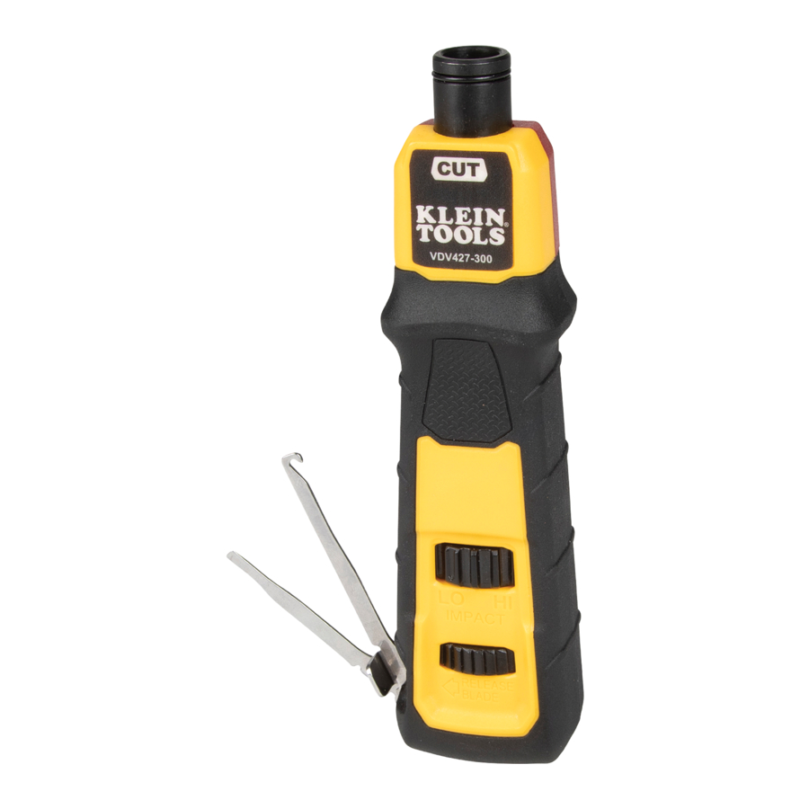
HOOK AND SPUDGER ACCESS AND STORAGE

To extend hook or spudger from storage nest in side of punchdown chassis, place finger-nail in notched portion of the hook or spudger and push away from the tool.
Extend hook or spudger to desired position and use to manipulate wire and or small components.
To store hook or spudger, gently push the hook or spudger towards the punchdown chassis until it is nested in the side of the punchdown chassis.
Documents / ResourcesDownload manual
Here you can download full pdf version of manual, it may contain additional safety instructions, warranty information, FCC rules, etc.
Advertisement


Need help?
Do you have a question about the VDV427-300 and is the answer not in the manual?
Questions and answers