Advertisement
Table of Contents
Contents
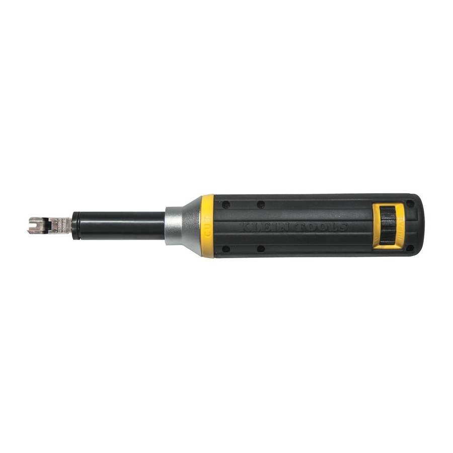
Klein Tools VDV427-821/-822 - Cushion-Grip Impact Punchdown Tool Manual
INSERTING BLADE
- Align slot in center of punchdown blade with the pin located on the inside of the punchdown tool's barrel and insert blade (Fig. 1).
- Rotate blade ¼ turn clockwise (Fig. 2).
Note: When blade is completely seated and locked, the cutting knife should align with the yellow side of the tool; note "CUT" is imprinted on yellow side of tool.
REMOVING BLADE

- Rotate blade ¼ turn counter-clockwise and pull gently (Fig. 2).
- Remove blade (Fig. 1).
ADJUSTING PUNCHDOWN FORCE
Note: Arrow on "Impact" dial aligns with selected force setting.

- To adjust from LO to HI, rotate dial to the right (Fig. 3).
- To adjust from HI to LO, rotate dial to the left (Fig. 4).
Note: See table below for recommended force settings.
| Impact (force) Setting | 66 Panel/Block/ Terminal | 110 Cross-Connect Panels/ Blocks/Keystone Jacks |
| LO | 24-26 gauge conductors | All |
| HI | 23 and larger gauge connectors | NOT RECOMMENDED |
110 TYPE PUNCHDOWN INSTRUCTIONS

- Insert the 110 terminating blade into the punchdown tool.
- Choose the correct end of the blade depending whether or not the wire is to be cut off. (Fig. 6 & 7 show use of the cutting end).
- Select the proper force setting – LO for all 110 type connections.
- Lay the wires in the wire slots (Fig. 5).
- Slide the blade into the wire slot and verify the orientation of the punchdown blade before moving to step 6 (Fig. 6). The "CUT" side of the blade should face the end of the wire to be cut.
- Push down on the cushion-grip end of the punchdown tool with the palm of your hand until it clicks (Fig. 7).
- Slide the blade out of the wire slot and make sure the wire is properly seated in the bottom of the wire slot between the insulation displacement connector's (IDC) blades. Proper use of the punchdown tool should ensure this is done correctly, but it is always a good idea to verify and test.
66 TYPE PUNCHDOWN INSTRUCTIONS

- Insert the 66 terminating blade into the punchdown tool.
- Choose the correct end of the blade depending whether or not the wire is to be cut off. (Fig. 9 & 10 show use of the cutting end).
- Select the proper force setting depending on the application (See table).
- Lay the wires in the openings on the post (Fig. 8).
- Slide the blade over the post and verify orientation of the punchdown blade before moving to step 6 (Fig. 9). The "CUT" side of the blade should face the end of the wire to be cut.
- Push down on the cushion-grip end of the punchdown tool with the palm of your hand until it clicks (Fig. 10).
- Slide the blade off of the post and make sure the wire is properly seated at the bottom of the post between the insulation displacement connector's (IDC) blades. Proper use of the punchdown tool should ensure this is done correctly, but it is always a good idea to verify and test.
Punchdown tools and accessories
| Description | Cat. No. |
| Cushion-Grip Impact Punchdown Tool Kit – 110/66 | VDV427-822 |
| Cushion-Grip Impact Punchdown Tool – 110/66 | VDV427-821 |
| Wire Pick | VDV327-103 |
| Dura-BladeTM 110/66 Cut Combination Punchdown Blade | VDV427-104 |
| Punchdown Tool Reach Extension Collar | VDV427-018 |

VideosKlein Tools VDV427-822 Unboxing And Review Video
Documents / ResourcesDownload manual
Here you can download full pdf version of manual, it may contain additional safety instructions, warranty information, FCC rules, etc.
Download Klein Tools VDV427-821/-822 - Cushion-Grip Impact Punchdown Tool Manual
Advertisement


Need help?
Do you have a question about the VDV427-821 and is the answer not in the manual?
Questions and answers