Oase BioMaster, BioMaster Thermo, BioMaster2, 250, 350, 600, 850 Manual
- Operating instructions manual (193 pages)
Advertisement
PRODUCT DESCRIPTION

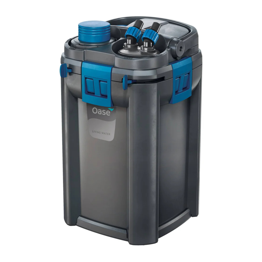
| Fig. A | BioMaster, BioMaster Thermo |
| 1 | HeatUp 150: BioMaster Thermo 250 HeatUp 200: BioMaster Thermo 350 HeatUp 300: BioMaster Thermo 600 HeatUp 400: BioMaster Thermo 850 |
| 2 | Operating instructions HeatUp 25/50/75/100/150/200/250/300/400 |
| 3 | Holding ring for HeatUp assembly |
| 4 | Blind plug |
| 5 | Handle, when the handle is hinged down there are two fasteners (10), locked |
| 6 | Unit head |
| 7 | Pre-filter with suction button |
| 8 | Connection unit with hose connectors, outlet and inlet |
| 9 | Fastener |
| 10 | Container, filled with filter media |
| 11 | Operating instructions BioMaster 250/350/600/850, BioMaster Thermo 250/350/600/850 |
| 12 | Rubber feet |
Overview

| Fig. B | Suction unit, flow-out unit | Quantity |
| 1 | Flow-out pipe | 3 |
| 2 | Suction pipe | 1 |
| 3 | Hose adapter | 2 |
| 4 | Hose | 1 |
| 5 | Angle piece, adjustable | 1 |
| 6 | Adapter, suction pipe | 1 |
| 7 | Suction basket | 1 |
| 8 | Suction cup | 5 |
| 9 | Terminal | 5 |
| 10 | Cover cap | 1 |
| 11 | Water distributor | 1 |
Intended use
Only use the product described in this manual as follows:
- BioMaster 250/350/600/850: Water filtering and recirculation.
- BioMaster Thermo 250/350/600/850: Water heating, filtering and recirculation.
- For operation with freshwater or saltwater.
- While adhering to the technical specifications. (→ Technical data)
The following restrictions apply to the unit:
- Only use indoors and for aquaristic purposes in the home (not for commercial use).
- Only operate with water at a water temperature of +4°C to +35°C.
Function description
Drawn in by a pump in the unit head, the water first flows through the pre-filter then from the bottom to the top through the superimposed layers of filter media. The water then flows back into the aquarium via the flow-out pipe or water distributor.
Foam filters with different pore densities, and Hel-X bio-elements serve as filter media.
In units with heater, the water is heated during its passage through the filter system.
ACCESSING THE UNIT
Careful handling of the heater

Hot surface! Risk of burns when touching the glass bulb.
- Switch off the heater and allow it to cool down before removing it from the water.
Risk of breaking the glass! The glass bulb of the heater can break and cause cuts.
- Take care when handling the heater.
- Allow the heater to cool down first. Do not immerse it in cold water or pour cold water over it.
Removing the heater
The heater has to be removed for cleaning and maintenance, and for removing the unit head.
How to proceed:
Fig. C

- Hinge up the handle.
- Unscrew the holding ring together with the heater counter-clockwise.
Fitting the heater
How to proceed:
Fig. D

- Screw the holding ring with heater clockwise into the threaded hole.
- To exchange the heater: Moisten the glass bulb with water and push the heater into the holding ring as far as it goes.
- Place the power connection cable into the cable guide.
- Hinge the handle down.
Removing the connection unit
The heater has to be removed for cleaning and maintenance, and for removing the unit head when hoses are connected.
How to proceed:
Fig. E

- Push the lever to the "UNLOCK" position.
- The lever can only be moved when the pre-filter is locked.
- The inlet and outlet are closed.
- Remove the connection unit.
Fitting the connection unit
How to proceed:
Fig. F

- Fit the connection unit and push it into the unit head as far as it goes.
- Ensure that the ridges on the connection unit are correctly aligned to the recesses on the unit head.
- Push the lever in the direction "LOCK".
- The inlet and outlet are open.
Removing the pre-filter
It has to be removed for cleaning and maintenance and for removing the unit head.
How to proceed:
Fig. G

- Push the lever to the "UNLOCK" position.
- The inlet and outlet are closed automatically.
- Pull out the pre-filter.
Fitting the pre-filter
How to proceed:
Fig. H

- Fit the pre-filter into the opening and firmly push it into the unit head as far as it goes.
- Ensure that the ridges on the pre-filter are correctly aligned to the recesses on the unit head.
- Push the lever to the "padlock closed" symbol.
- The pre-filter is locked.
Dismantling the unit head
It has to be removed for cleaning and maintenance and for changing the filter media.
Prerequisite:
- The heater has been removed. (→ Removing the heater)
- The connection unit has been removed. (→ Removing the connection unit)
- The pre-filter has been removed. (→ Removing the pre-filter)
How to proceed:
Fig. I

- Hinge up the handle.
- Undo the fasteners.
- Remove the unit head.
Fitting the unit head
How to proceed:
Fig. J

- Check that the seal on the unit head is correctly positioned.
- Clean the seal, replace it if damaged.
- Ensure that the filter baskets are correctly assembled and aligned.
- Fit the unit head onto the container.
- Ensure that the opening for the pre-filter is aligned to the recess in the filter baskets.
- Lock the fasteners in place.
- Hinge the handle down.
INSTALLATION AND CONNECTION
Order of tasks to be carried out:
- Fit the unit feet (→ Fitting the unit feed)
- Prepare the filter media (→ Cleaning/replacing the filter media)
- As an option: OASE HeatUp Retrofitting (heater) (→ Retrofitting the heater)
- Install the unit.
- Install the unit next to or under the aquarium. Note the maximum head height. (→ Technical data)
- Establish the connections (→ Establishing the con nections)
Fitting the unit feed
How to proceed:
Fig. K

- Twist the rubber feet into the openings of the con tainer base.
Retrofitting the heater
BioMaster 250/350/600/850 can be retrofitted with OASE HeatUp.
- A holding ring is required for fitting (provided in the delivery scope).

![]() recommended
recommended
![]() possible
possible
– not possible

 recommended
 possible
Prerequisite:
- The pump is switched off. (→ Switching off the unit)
 N O T E
When the filter is filled with water, water may spill when the heater is inserted.
- Take measures to collect any spillage.
How to proceed:
Fig. L

- Unscrew the blind plug counter-clockwise and remove.
- Push the heater into the holding ring as far as it goes.
- Tip: Moisten the glass bulb with water before inserting.
- Fit the heater. (→ Fitting the heater)
Establishing the connections
Assembling the suction unit
How to proceed:
Fig. M

Assembling the flow-out unit
How to proceed:
Fig. N

- Assemble the flow-out unit.
- The water distributor can be used instead of the flow-out pipe.
Connecting the hose
Fig. O, P
The procedure is identical for the inlet (IN) and outlet (OUT).

- Fasten the suction unit and flow-out unit in the aquarium using suction cups.
COMMISSIONING/START-UP
For initial start-up or after thorough cleaning, it is necessary to expel air from the filter system. When the container, suction unit and hose are free of trapped air, the pump can convey the water by itself through the filter system. (→ Expelling air from the filter system)
N O T E
Thoroughly rinse out all filter material with warm tap water before using for the first time in order to remove any soiling. (→ Cleaning/replacing the filter media)
Expelling air from the filter system
Prerequisite:
- The pump is switched off. (→ Switching off the unit)
How to proceed:
Fig. Q

- Press the suction button and release it until the water flows out of the tank into the filter.
- The filter is completely flooded when water emerges from the flow-out unit.
Switching on the unit
N O T E
Ensure that the pump never runs dry! The pump will be destroyed.
- Regularly check the water level and circulation in the filter and in the aquarium.
N O T E
Risk of fire due to the hot surface of the heater! The heater and filter can be destroyed by the generated heat.
- Do not switch the heater on until the filter is completely filled with water, switched on and the water is continuously circulated.
- Switch off the heater and allow it to cool down before removing it from the water.
How to proceed:
Fig. R

- Route each power connection cable such that it forms a drip loop.
- Connect the power connection cable to the power supply.
- The pump will switch on immediately.
- Trapped air in the filter can cause noise. The trapped air escapes shortly after the pump starts up.
- Unit with heater: Set the water temperature on the heater and switch on the heater. (→ Heater operating manual).
Switching off the unit
How to proceed:
- Disconnect the unit from the power supply
- Unit with heater: Disconnect the unit and heater from the power supply
Setting the flow rate
How to proceed:
Fig. S

- Move the lever on the connection unit to set the desired flow rate
- "LOCK": Maximum flow rate
- "UNLOCK": No flow, the outlet is closed.
MAINTENANCE AND CLEANING
- If necessary, clean with clear water using a soft brush.
- Do not use cleaning agents or chemical solutions. We recommend using OASE PumpClean for removing calcium deposits.
- Cleaning and replacement cycles for filter media are dependent on the size of the aquarium and the number of fish. Therefore, it is necessary to clean and replace the filter media as required to ensure optimum filter performance.
- If there are several foam filters: Clean or replace the foam filters at different times. This saves enough useful bacteria to ensure good biological filtration of the water.
N O T E
Thoroughly rinse out all filter material with warm tap water before using for the first time in order to remove any soiling. (→ Cleaning/replacing the filter media)
Cleaning and maintenance work:
| Area | Tasks to be carried out |
| Foam filter, pre-filter | (→ Cleaning/replacing the foam filter of the pre-filter) |
| Filter media, container | (→ Cleaning/replacing the filter media) |
| Heater |  HeatUp 25/50/75/100/150/200/250/300/400 HeatUp 25/50/75/100/150/200/250/300/400 |
| Impeller unit, pump casing | (→ Cleaning/replacing the impeller unit) |
| Valve box, pre-filter | (→ Cleaning the valve box of the pre-filter) |
| Suction chamber, pre-filter | (→ Cleaning the suction chamber of the pre-filter) |
N O T E
The cycle for cleaning the foam filter in the pre-filter is longer if a coarser foam filter is used.
Cleaning/replacing the foam filter of the pre-filter
Prerequisite
- The pre-filter has been removed. (→ Removing the pre-filter)
How to proceed:
Fig. T

- Turn the casing until the locking hooks are pushed in, then pull off the casing.
- Remove the pre-filter pipe and foam filters.
- BioMaster 250: 4 foam filters.
- BioMaster 350: 5 foam filters.
- BioMaster 600: 6 foam filters
- BioMaster 850: 7 foam filters
- Rinse the foam filters in warm water. If necessary, replace the foam filters.
- Assemble the pre-filter in the reverse order.
- Ensure that the locking hooks lock in place in the casing.
Cleaning/replacing the filter media
Fig. U
Filter media on delivery:

| a | Foam filter 30 ppi |
| b | Foam filter 20 ppi |
| c | Hel-X bio-elements, always place them contained in the bag into the strainer casing |
Prerequisite
- The unit head is removed. (→ Dismantling the unit head)
How to proceed:
Fig. U
- Remove all filter baskets.
- Clean the filter baskets and container.
- Use water to flush the filter media from the aquarium.
- If necessary, replace the filter media. Rinse the new filter media thoroughly with warm tap water prior to its first use.
- Insert the parts in the container in the reverse order.
- Carefully fit the filter baskets in the bottom recess in the container. Correctly position the prefilter.
- Ensure that the filter cover is positioned on the foam filter in the top filter basket.
- Reassemble the unit in the reverse order.
Cleaning/replacing the impeller unit
Prerequisite
- The unit head is removed. (→ Dismantling the unit head)
How to proceed:
Fig. V

- Pull off the venting element.
- Turn the pump lid counter-clockwise (bayonet lock) and remove.
- Remove the impeller unit and clean. If necessary, replace.
- Fit the impeller unit, replace the pump lid and lock (turn clockwise).
- Ensure that the two rubber bearings are correctly seated.
- Reassemble the unit in the reverse order.
Cleaning the valve box of the pre-filter
The valve box only has to be cleaned if venting does not function even though the foam filters of the prefilter have been cleaned.
Prerequisite
- The pre-filter has been removed. (→ Removing the pre-filter)
How to proceed:
Fig. W

- Undo the fasteners and pull off the valve box.
- If necessary, carefully lift the fasteners using a screwdriver.
- Remove the valve seal and both valve flaps. Clean all parts.
- Assemble the valve box in the reverse order.
- Ensure that the fitted valve flaps can be easily moved.
- Note: Ensure that the opening in the valve seal is precisely aligned to the opening in the suction chamber.
Cleaning the suction chamber of the pre-filter
The suction chamber only has to be cleaned if venting does not function even though the foam filters and valve box of the pre-filter have been cleaned.
Prerequisite
- The pre-filter has been removed. (→ Removing the pre-filter)
There is a strong spring in the suction chamber that can act like a projectile.
Risk of injury due to parts flying around
- When opening the suction button, do not point it at persons.
- Firmly hold the suction button.
How to proceed:
Fig. X

- Press in the engagement hooks, hold and turn the locking ring counter-clockwise (bayonet lock).
- Carefully lift the suction button until the tension of the spring is relieved.
- Remove the suction button and spring.
- Clean the suction chamber.
- Assemble the suction chamber in the reverse order.
WEAR PARTS
- Filtration medium
- Impeller unit
- Suction cups
MALFUNCTION REMEDY
| Malfunction | Cause | Remedy |
Unit does not start up | No mains voltage | Check the mains voltage. |
| Impeller unit blocked | Clean | |
| Air in the filter | Vent the filter. Move the filter from side to side, if necessary, to allow the remaining air to escape. | |
Water flow insufficient | Impeller unit soiled | Clean |
| Impeller unit worn | Replace the impeller unit. | |
| The flow is not correctly set. | Correct the setting. | |
| Foam filter of the pre-filter soiled | Clean | |
| Filter media in the container soiled | Clean | |
| Suction basket clogged | Clean | |
| Pipework soiled | Clean suction unit, flow-out unit and hoses. | |
Insufficient filtering performance | Foam filter of the pre-filter soiled | Clean |
| Foam filter of the pre-filter worn | Replace | |
| Filter media in the container soiled | Clean | |
| Filter media in the container worn | Replace | |
Insufficient water heating (only units with heater) | Heater defective | Replace |
| Heater not calibrated | Calibrate | |
| Water temperature incorrectly set on the heater | Correct the water temperature setting on the heater. | |
| Water flow insufficient | See malfunction "Water flow insufficient" | |
The filter cannot be vented | Valve box in the pre-filter blocked | Clean the valve box. |
| Filter is not below the surface of the water. | Install the filter below the surface of the water. | |
Increased noise | Air in the filter | Move the filter from side to side to allow the remaining air to escape. |
TECHNICAL DATA
| Description | BioMaster, BioMaster Thermo | |||||
| 250 | 350 | 600 | 850 | |||
| Rated voltage | V AC | 230 | 230 | 230 | 230 | |
| Mains frequency | Hz | 50 | 50 | 50 | 50 | |
| Protection type | IPX4 | IPX4 | IPX4 | IPX4 | ||
| Power consumption, filter | W | 15 | 18 | 22 | 32 | |
| BioMaster Thermo | Power consumption, heater | W | 150 | 200 | 300 | 400 |
| Flow rate | Max. | l/h | 900 | 1100 | 1250 | 1550 |
| Head height | Max. | m | 1,3 | 1,4 | 1,8 | 2,2 |
| Max. head height | Max. | m | 1,8 | 1,8 | 1,8 | 1,8 |
| Filter volume | l | 4,4 | 5,6 | 6,8 | 8 | |
| Pre-filter volume | l | 0,4 | 0,5 | 0,6 | 0,7 | |
| Recommended for an aquarium volume of | l | 250 | 350 | 600 | 850 | |
| Length of power connection cable | m | 1,5 | 1,5 | 1,5 | 1,5 | |
| Connection of hose connectors | Diameter | mm | 17 | 17 | 17 | 17 |
| Dimensions | Length | mm | 240 | 240 | 240 | 240 |
| Width | mm | 240 | 240 | 240 | 240 | |
| Height | mm | 370 | 425 | 480 | 535 | |
| Weight | kg | 4,1 | 4,5 | 5,0 | 6,7 | |
SYMBOLS ON THE UNIT
 | The unit is protected against the ingress of splash water. |
 | Protection class II. The unit is securely disconnected from the power supply by a reinforced or double insulation. |
 | Only use the unit in indoor spaces. |
 | Do not dispose of the unit with normal household waste. |
 | Read the operating instructions. |
SAFETY INFORMATION

- This unit can be used by children aged 8 and above and by persons with reduced physical, sensory or mental capabilities or lack of experience and knowledge if they are supervised or have been instructed on how to use the unit in a safe way and they understand the hazards involved. Do not allow children to play with the unit. Only allow children to carry out cleaning and user maintenance under supervision.
- Switch off all units in the aquarium or disconnect the power plugs of all units before reaching into the water.
- Only connect the unit if the electrical data of the unit and the power supply match.
- Only plug the unit into a correctly installed outlet.
- The device is to be supplied through a residual current device (RCD) having a rated residual operating current not exceeding 30 mA.
- Never operate the unit if the housing is defective!
- Never operate the unit if an electrical cable is defective!
- If the electrical connection cable of the device is damaged, dispose of the device. The connection cable cannot be replaced.
- Never pull on electric cables. In particular, never carry units on their cables.
- Route lines in such a way that they are protected from damage and do not present a tripping hazard.
- Disconnect the power plug before carrying out any work on the unit.
- Only open the unit housing or its attendant components if this is explicitly specified in the operating instructions.
- Only carry out work on the unit that is described in this manual.
- Only use original spare parts and accessories.
- Never carry out technical changes to the unit.
- Protect the plug connection from moisture.
Documents / ResourcesDownload manual
Here you can download full pdf version of manual, it may contain additional safety instructions, warranty information, FCC rules, etc.
Download Oase BioMaster, BioMaster Thermo, BioMaster2, 250, 350, 600, 850 Manual
Advertisement


Need help?
Do you have a question about the BioMaster and is the answer not in the manual?
Questions and answers