OASE BioSmart 5000/10000 Manual
- Operating instructions manual (212 pages) ,
- Operating instructions manual (118 pages) ,
- Operating instructions manual (21 pages)
Advertisement
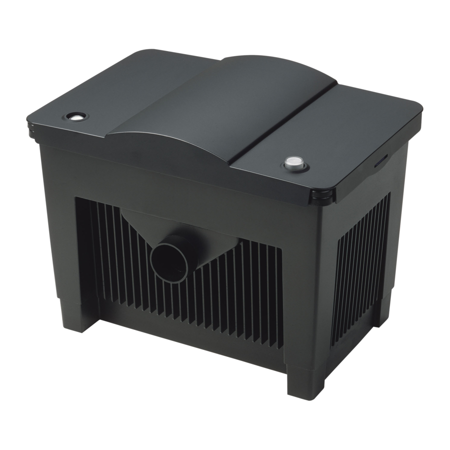
Overview

| Part | Description | QTY |
| A | Container for pond additives | 1 |
| B | Water supply | 1 |
| C | Slide valve | 1 |
| D | Sludge drain | 1 |
| E | Filter cleaning handle function | 4 |
| F | Water level indicator | 1 |
| G | Water outlet | 1 |
| H | Fresh water supply | 1 |
WARNINGS AND CAUTIONS SYMBOLS
Symbols used in these instructions
The symbols used in this operating manual have the following meanings:
 | Risk of injury to persons due to dangerous electrical voltage. This symbol indicates an imminent danger, which can lead to death or severe injuries if the appropriate measures are not taken. |
 | Risk of personal injury caused by a general source of danger. This symbol indicates an imminent danger, which can lead to death or severe injuries if the appropriate measures are not taken. |
 | Important information for trouble-free operation. |
Intended use
BioSmart 5000/10000, referred to in the following as "unit", may only be used as specified in the following:
- For mechanical and biological cleaning of ponds.
- Operation under observance of the technical data.
The following restrictions apply to the unit:
- Minimum safety distance between the unit and the water: 6.6 ft.
- Never use the unit to convey fluids other than water.
- Do not use for commercial or industrial purposes.
- Do not use in conjunction with chemicals, foodstuff, easily flammable or explosive substances.

Ensure that the filter will not overflow. Danger of emptying the pond.
Use other than that intended
This unit can be dangerous and cause harm if not used in accordance with these instructions. Any use not in accordance with these instructions or modification(s) to the unit will void the limited warranty.
Installation
- Lay the outlet pipe for the water outlet into the pond and the hose for the sludge drain into the sewage system or flower bed with a sufficient gravity (i.e. slightly downhill).
![]()
- If the outlet pipe is not sloped adequately towards the pond the filter can backup and overflow.
- Connect the outlet pipe to the filter outlet using the supplied adapter kit in the box.

- Make sure to place the O-ring on the inside of the adapter to keep the adapter from falling off outlet.
- Secure the adapter, pipe and sleeve together with glue
- Place the unit at a flood protected position at a distance from the pond edge of at least 6.6 ft on a firm and level ground.
![]()
- Ensure unrestricted access to the cover to be able to carry out work on the unit.


- If fitting an OASE UVC Vitronic pre-cleaning unit (not included) follow the steps in the Vitronic manual for connection to the filter. Once the UVC is connected skip BioSmart manual steps 3-6 and proceed from step 7.
- If you are not using an OASE UVC Vitronic pre-cleaning unit (not included) proceed with the steps below
- To avoid pressure loss and reduced flow, use a hose connection that is as close to the maximum size diameter of the pump outlet; avoid bends and lay well protected.
![]()
- Saw off the open stepped hose nozzle at the corresponding mark depending on the hose size being used.
- Push and turn the hose onto the open stepped hose nozzle and secure with a hose clamp.
![]()
- Place a flat sealing ring on the thread of the stepped hose nozzle
![]()
- Push the thread of the stepped hose nozzle through the water inlet
- Insert an O ring on the thread from inside.
- Screw the inlet nozzle on the stepped hose nozzle from inside ensuring that the opening points downward.


- Lay the hose so that it cannot be stepped on, avoid kinks.
- Connect the other end of the hose to the filter pump (not included).
- Use the filter specifications to properly pair your filter with the correct filter pump.
- Follow the instruction manual that is included with the pump for proper connection to the filter.
- The second water inlet will need to be closed off using the closed hose nozzle.
- Place a flat sealing ring on the thread of the closed hose nozzle

- Push the thread of the closed hose nozzle through the water inlet
- Insert an O ring on the thread from inside.
- Screw the inlet nozzle on the closed hose nozzle from inside ensuring that the opening points downward.
- During normal filter operation, the sludge drain should be closed using the cover cap.
![]()
- To permanently fit a 2" hose to the sludge drain, unscrew the cover cap from the dirt drain and push the union nut over the 2" hose nozzle.
![]()
- Push on the hose and secure with the hose clip.
- Insert the flat sealing ring in the union nut and firmly screw-tighten the 2" hose nozzle including the union nut on the sludge drain.
- As an option, you can permanently fit a 1/2" connection for a garden hose to the fresh water connection and to connect the OASE AquaOxy 400 pond aerator (not included) to the air connection to ensure an adequate oxygen supply to the pond.
![]()
- Follow the instruction manual that is included with the pond aerator for proper connection to the filter.


Start-up
- This filter requires connection to a pump to operate. Follow pump instruction manual for proper power connection.
- If also connecting a UVC to this filter follow the UVC instruction manual for proper power connection.
- Prior to starting up the unit, check that all clamps on the internal cover are closed. The clamps for pond additives can be used to supply additives such as filter starters to the filter and the pond (optional).
- The BioSmart filter is a biological filter system and requires several weeks after its first installation to reach its full biological effect, and must be run continuously to retain the biological efficiency.
- Switching the filter system on: Connect each power plug to the socket.
Maintenance and cleaning
Attention! Dangerous electrical voltage.
Possible consequences: Death or serious injuries.
Protective measures:
- Prior to reaching into the water, disconnect the power supply to all units used in the water.
- Disconnect the power plug prior to carrying out work on the unit.
- Only clean the unit when required, do not use chemical cleaning agents to permit the filter biology to optimally develop, knowing that cleaning agents kill the bacteria in the foam filters.
- Clean the filter immediately when the float switch in the water level indicator becomes visible from outside on the lid.
- Switch off the pump and open the unit cover.
Cleaning the foam filters
- To mechanically clean the foam filters, pull up on the cleaning handles slowly, hold at the top, then slowly push the cleaning handles down. Repeat this action several times.
![]()
- If necessary, unscrew the cover cap from the sludge drain, open the slide valve. Allow the water to drain completely, then close the slide valve again. Repeat the cleaning process 2-3 times, until water comes out clear.
![]()


Removing the foam filters
- It may be necessary to remove the foam filters from the unit and clean them more thoroughly in a bucket of pond water.
- Press the engagement of the cleaning handles to the side until the connection to the inner cover disengages.
- Release the clamps at the inner cover and remove cover.
![]()
- Spray clean the inner cover.
- Pull the foam filters from the foam filter holder, spray clean the container, the cover and the foam filters with clean water.
![]()


- Reinsert the cleaned foam filters in the foam filter holders (the green foam filter in the black foam holder).
- Pull the handles of the foam filter holders through the slots in the inner cover from below until the foam filter holders engage and click into place.
![]()

- Insert the inner cover into the filter container and fold over all clamps, fit filter cover and switch on the pump.
- Replace the foam filters if the float switch of the water level indicator keeps showing a medium to heavy soiling following the cleaning process.
Cleaning the water level indicator
- Turn the water level indicator counter-clockwise through approx. 30° and pull out of the inner cover.
![]()

- Remove the plug and the float switch out of the housing of the water level indicator and clean using clear water.
- Reassemble in the reverse order such that the float switch can move freely in the housing.
Storage/Winterization
- Put the unit out of operation at water temperatures below 46°F (8°C) or, at the latest, when freezing temperatures are to be expected.
- Drain and thoroughly clean the unit, check for damage.
- Remove, clean, dry and store all filters in a frost-free environment.
- Ensure that the storage place is inaccessible to children.
- Cover the filter container such that the ingress of rain water is excluded.
- Drain all hoses, pipes and connections as far as possible.
Wear parts
Foam filters are wear parts and are excluded from the warranty.
Spare parts
The use of original parts from OASE ensures continued safe and reliable operation of the unit. Please visit our website for spare parts drawings and spare parts. www.oase-livingwater.com
Troubleshooting
| Issue | Cause | Solution |
| Water stays cloudy | Unit has been in operation only for a short time | The complete biological cleaning effect is only achieved after several weeks |
| Inadequate pump capacity | Readjust the pump capacity | |
| Water extremely soiled | Remove algae and leaves from the pond, do a partial water change | |
| Foam filters soiled | Clean foam filters | |
| Excessive fish and animal population | Guide value: approx. 2 ft (60 cm) fish length on 1 m2 pond water |
Questions, problems, missing parts?
Before returning to your retailer, call us at 1-866-627-3435, 8 a.m.-6 p.m., EST, Monday-Friday, or email us at customercare@oase-livingwater.com. Or visit our website at www.oase-livingwater.com

Documents / Resources
References
Download manual
Here you can download full pdf version of manual, it may contain additional safety instructions, warranty information, FCC rules, etc.
Advertisement


Need help?
Do you have a question about the BioSmart 5000 and is the answer not in the manual?
Questions and answers