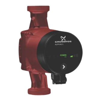
Grundfos ALPHA2 L Series Installation And Operating Instructions Manual
Hide thumbs
Also See for ALPHA2 L Series:
- Installation manual ,
- Installation and operating instructions manual (41 pages) ,
- Instructions manual (31 pages)
Table of Contents
Advertisement
Advertisement
Table of Contents

Related Manuals for Grundfos ALPHA2 L Series


Summary of Contents for Grundfos ALPHA2 L Series
- Page 1 GRUNDFOS INSTRUCTIONS GRUNDFOS ALPHA2 L Installation and operating instructions...
-
Page 2: Table Of Contents
Product introduction Indicates a hazardous situation which, if not avoided, Product description will result in death or serious personal injury. Application Advantages of installing a GRUNDFOS ALPHA2 L Intended use WARNING Pumped liquids Indicates a hazardous situation which, if not avoided, System pressure could result in death or serious personal injury. -
Page 3: Notes
1.2 Notes 3. Installing the product The symbols and notes below may appear in Grundfos DANGER installation and operating instructions, safety instructions and Electric shock service instructions. Death or serious personal injury - Switch off the power supply before starting any A blue or grey circle with a white graphical symbol work on the product. -
Page 4: Control Box Positions
Hot surface through the pump. Minor or moderate personal injury See section 14.2 Installation dimensions, GRUNDFOS ALPHA2 L - The pump housing may be hot due to the pumped XX-40, XX-50, XX-60. liquid being scalding hot. Close the isolating valves •... -
Page 5: Changing The Control Box Position
4. Electrical installation Fill the system with the liquid to be pumped or open the isolating valves when the position of the control DANGER box has been changed. Electric shock Death or serious personal injury - All electrical connections must be carried out by a 3.4 Changing the control box position qualified electrician in accordance with local The control box position can be changed in steps of 90 °. -
Page 6: Assembling The Plug
4.1 Assembling the plug Step Action Illustration Step Action Illustration 7 mm Fit the cable gland and plug cover to Screw the cable the cable. Strip the 12 mm gland onto the cable conductors as 17 mm power supply plug. 0.5 - 1.5 mm illustrated. -
Page 7: Starting Up The Product
5. Starting up the product 5.3 Venting of heating systems 5.1 Before startup Do not start the pump until the system has been filled with liquid and vented. The required minimum inlet pressure must be available at the pump inlet. See section 14. -
Page 8: Product Introduction
110 °C Pumped liquids and operating conditions Fig. 7 6.2 Application 6.5 Pumped liquids The GRUNDFOS ALPHA2 L circulator pump is designed for the CAUTION circulation of water in heating systems. Flammable material The pump is suitable for the following systems: Minor or moderate personal injury. -
Page 9: Identification
7. Identification 7.2 Type key 7.1 Nameplate Example ALPHA2 L 25 -40 Pump type Nominal diameter (DN) of inlet and outlet ports [mm] ALPHA2L 25-40 180 Maximum head [dm] ALPHA2 25-40 180 ALPHA2 L 25-40 180 : Cast-iron pump housing N: Stainless-steel pump housing POWER AUTO... -
Page 10: Accessories
8. Accessories Accessories for GRUNDFOS ALPHA2 L. See fig. 9. Accessories include • fittings (unions and valves) • insulating kits (insulating shells) • plug. Product No Product No 529921 15-XX 25-XX (A) 3/4" 505821 529922 25-XX 25-XX (A) 1" 32-XX... -
Page 11: Operating Panel
The pump setting is indicated by seven different light fields. See fig. 11. POWER ALPHA2 L 25-40 180 POWER III II I Fig. 11 Seven light fields Fig. 10 GRUNDFOS ALPHA2 L operating panel The operating panel comprises: Number of button Light field Description Pos. -
Page 12: Setting The Pump
10. Setting the pump 10.1 Pump setting for system type POWER POWER POWER ( OK ) POWER POWER POWER OWER ( OK ) POWER POWER POWER ( OK ) POWER POWER POWER ER ( OK ) Fig. 12 Selection of pump setting for system type Factory setting = highest proportional-pressure curve (PP2). -
Page 13: Systems With Bypass Valve Between Flow And Return Pipes
11. Systems with bypass valve between flow and return pipes 11.1 Purpose of bypass valve BYPASS BYPASS min. POWER (OK) POWER (OK) POWER (OK) POWER POWER POWER ER (OK) Fig. 13 Systems with bypass valve Bypass valve The purpose of the bypass valve is to ensure that the heat from the boiler can be distributed when all valves in the underfloor- heating circuits and/or thermostatic radiator valves are closed. -
Page 14: Pump Settings And Pump Performance
12. Pump settings and pump performance 12.1 Relation between pump setting and pump performance Figure shows the relation between pump setting and pump performance by means of curves. See also section 15. Performance curves. POWER AUTO Fig. 14 Pump setting in relation to pump performance Setting Pump curve Function... -
Page 15: Fault Finding The Product
Death or serious personal injury Death or serious personal injury - Switch off the power supply before starting any - A damaged product must be repaired by Grundfos work on the product. Make sure that the power or a service workshop authorised by Grundfos. -
Page 16: Technical Data And Installation Dimensions
14. Technical data and installation dimensions 14.1 Technical data Operating conditions Relative humidity Maximum 95 % RH System pressure Maximum 1.0 MPa, 10 bar, 102 m head Liquid temperature Minimum inlet pressure ≤ 75 °C 0.005 MPa, 0.05 bar, 0.5 m head Inlet pressure 90 °C 0.028 MPa, 0.28 bar, 2.8 m head... -
Page 17: Installation Dimensions, Grundfos Alpha2 L
14.2 Installation dimensions, GRUNDFOS ALPHA2 L XX-40, XX-50, XX-60 Dimensional sketches and table of dimensions Fig. 15 Dimensional sketches, ALPHA2 L XX-40, XX-50, XX-60 Dimensions Pump type 1 1/2 ALPHA2 L 25-40 180 ALPHA2 L 32-40 180 1 1/2 ALPHA2 L 15-50 130*... -
Page 18: Performance Curves
15. Performance curves 15.1 Guide to performance curves Each pump setting has its own performance curve (Q/H curve). A power curve (P1 curve) belongs to each Q/H curve. The power curve shows the pump power consumption (P1) in Watt at a given Q/H curve. -
Page 19: Performance Curves, Alpha2 L
15.3 Performance curves, ALPHA2 L XX-40 [kPa] Q [m³/h] Q [l/s] Q [m³/h] Fig. 17 ALPHA2 L XX-40 15.4 Performance curves, ALPHA2 L XX-50 [kPa] Q [m³/h] Q [l/s] Q [m³/h] Fig. 18 ALPHA2 L XX-50... -
Page 20: Disposing Of The Product
This product or parts of it must be disposed of in an environmentally sound way: 1. Use the public or private waste collection service. 2. If this is not possible, contact the nearest Grundfos company or service workshop. The crossed-out wheelie bin symbol on a product means that it must be disposed of separately from household waste. - Page 21 GRUNDFOS Pumps (Hong Kong) Ltd. Turkey BOMBAS GRUNDFOS DO BRASIL Unit 1, Ground floor Norway GRUNDFOS POMPA San. ve Tic. Ltd. Sti. Av. Humberto de Alencar Castelo Branco, Siu Wai Industrial Centre GRUNDFOS Pumper A/S Gebze Organize Sanayi Bölgesi 29-33 Wing Hong Street &...
- Page 22 95047490 0819 ECM: 1267507 www.grundfos.com...
Need help?
Do you have a question about the ALPHA2 L Series and is the answer not in the manual?
Questions and answers