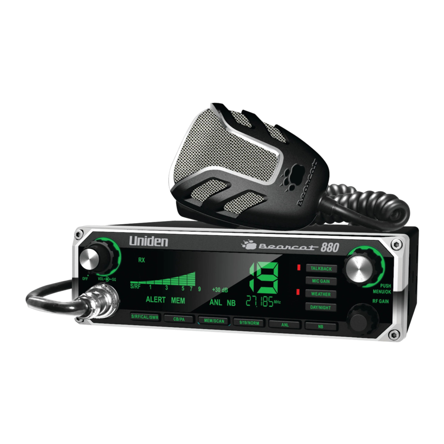
Uniden Bearcat 880 - Radio Transceiver Manual
- Owner's manual (22 pages) ,
- Owner's manual (16 pages) ,
- Owner's manual (16 pages)
Advertisement
- 1 UNPACKING
- 2 CONTROLS AND FUNCTIONS
- 3 INSTALLATION
- 4 USING YOUR BEARCAT 880
- 5 PREVENTIVE MAINTENANCE
- 6 MAINTENANCE
- 7 TROUBLESHOOTING
- 8 SPECIFICATIONS
- 9 RADIO CODE DEFINITIONS
- 10 SAFETY NOTICE
- 11 Documents / Resources
![]()
UNPACKING
Your Bearcat 880 contains the following:
- Bearcat 880 CB 2-way mobile radio
- Microphone
- Mounting Bracket Kit
- DC Power Cord
- 6-pin to 4-pin microphone adapter
- Reference Guide
- Part 95 Subpart D (FCC Rules)
If any items are missing or damaged, contact your place of purchase immediately.
CONTROLS AND FUNCTIONS

- Volume Control knob with Power On/Off. Turn the knob clockwise until it clicks to turn power on or counterclockwise until it clicks to turn power off.
- SQUELCH knob: Reduces background noise when there is no incoming signal.
- S/RF/CAL/SWR Meter: Displays Send/Receive signal strength, RF Power, and SWR reading.
- Channel Number display.
- Operation buttons and associated LEDs:
- Talkback: Talkback lets you monitor yourself when transmitting. Press Talkback to activate the function (LED = on). With Talkback active, press PTT and adjust the volume with the Volume Control knob. (Levels 00 - 15)
- MIC Gain: Adjusts microphone sensitivity. Delivers up to 100% modulation. With MIC Gain active, press PTT and adjust the gain levels with the Volume Control knob. (Levels 00 - 04)
NOTE
If Talkback is on when MIC Gain is also on, Talkback volume increases. - Weather: Press to toggle between Weather and CB channels. Turn Channel Selector to cycle through the 7 weather channels. (LED off = CB channels; LED on = Weather channels)
Press and hold to turn Weather Alert on and off.![]() displays.
displays. - Day/Night: Adjusts LCD backlight sensitivity between Day and Night modes. (LED off = Day; LED on = Night)
- Channel Selector/MENU/OK. Press the inner MENU/OK button to select a menu option or other selection. Turn the outer Channel Selector knob to:
- ƒSelect channels
- ƒSelect menu modes
- ƒChange scan resume direction (up or down)
- ƒControl Talkback volume
- Control Mic gain level
- ƒControl Calibration volume
NOTE
All channels except Channel 9 may be used for normal communication. The FCC reserves Channel 9 for emergencies involving the immediate safety of individuals or protection of property. Use Channel 9 to render assistance to a motorist.
This is an FCC rule and applies to all CB operators.
- Microphone socket.
- Indicators turn on when the function is turned on.
- S/RF/CAL/SWR: Push to to check RF signal strength, calibration, and SWR reading.
- CB/PA: Selects CB (Citizens Band) or PA (Public Address).
NOTE
Do not use the PA function unless an external speaker is connected. - MEM/SCAN: Press to start or stop scanning modes [All Channel Scan and Memory Scan]. Press and hold to set or clear channel memory while in Memory mode.
- 9/19/NORM: Press to switch between emergency channel 9, channel 19, and standard CB channels.
- Frequency Display: Displays the MHz of the selected channel. Also displays menu options.
- ANL: Turns ANL (Automatic Noise Limiter) feature on and off. ANL reduces external noise.
- NB: Turns NB (Noise Blanker) feature on and off. NB reduces interference from vehicle ignition systems.
- RF Gain knob: Improves reception in strong signal areas.

- Antenna socket: Connects antenna to the unit.
- PA SP: Connects optional external 8-ohm, 4-watt speaker for use as a public address system.
![warning]() To prevent acoustic feedback, separate the microphone from the speaker when operating the PA at high output levels.
To prevent acoustic feedback, separate the microphone from the speaker when operating the PA at high output levels. - EXT. SP: Connects an 8-ohm 4-watt speaker to remotely monitor the receiver.
![warning]() When the external speaker is plugged in, the internal speaker is off.
When the external speaker is plugged in, the internal speaker is off. - POWER: Connects DC power to transceiver.
- Fuse.
- PTT: Push-to-Talk.
 displays.
INSTALLATION
MOBILE INSTALLATION
NOTE
Plan the location of the transceiver and microphone bracket before beginning installation.
- Select a location that is convenient for operating the radio but does not interfere with the driver or passenger.
- Install bracket with self-tapping screws provided.
- Connect power cords.
- Attach the microphone bracket to side of the radio.
- Attach radio to bracket.
Mobile Antenna
Because the maximum power output of the transmitter is limited by the FCC, the quality of your antenna is very important. To achieve the maximum transmission distance, Uniden strongly recommends that you install only a high quality antenna. You have just purchased a superior transceiver - don't diminish its performance by installing an inferior antenna.
Only a properly matched antenna system will allow maximum power transfer from the 50 ohm transmission line to the radiating element. Your Uniden dealer is qualified to help you select the proper antenna for your requirements. A whip style antenna may be used for automobile installation.
A short 'loaded' whip antenna is easier to install on an automobile, but its efficiency is less than that of a full quarter-wave whip antenna.
Connecting the Power Cords
Uniden recommends connecting the power lead to the Ignition Switch Accessory Terminal. This way, the transceiver is automatically turned off when the ignition switch is turned off.
As an alternative, the power cord may be connected to an available terminal on the fuse block or to a point in the wiring harness. However, caution must be taken to prevent a short circuit. If in doubt, contact your vehicle dealer for information.
Ground Information
NOTE
This transceiver may be installed and used in any 12-volt DC negative ground system vehicle.
Negative Ground System
With a negative ground system, the negative (-) battery terminal is usually connected to the vehicle motor block.
Connect the red DC power cord from the transceiver to the positive (+) battery terminal or other convenient point. Then connect the black power cord to the vehicle chassis or negative (-) battery terminal.

INSTALL 6-PIN TO 4-PIN ADAPTER
The Bearcat 880 is pre-configured for Uniden's new 6-pin wireless, noisecancelling technology, available in 2012. Your Bearcat 880 comes with an adapter to connect the radio's 6-pin microphone to a current standard 4-pin microphone.
- Insert the 6-pin side of the adapter into the Bearcat 880 6-pin microphone connection.
- Plug a standard 4-pin microphone connector into the 4-pin side of the adapter.
MARINE INSTALLATION
Consult your dealer for information regarding marine installation. It is important to adequately ground the system and to prevent electrolysis between the fittings in the hull and the water.
USING YOUR BEARCAT 880
CB MODE
NOTE
Be sure that the power source, antenna, and microphone are properly connected before proceeding.
BASIC SETTINGS
- Turn unit on. Set volume to a comfortable level.
- Select channel.
- Set noise limitations as desired (ANL/NB).
- Adjust Squelch.
- Turn SQUELCH fully clockwise so only strong signals can get through.
- Turn SQUELCH fully counterclockwise until you hear a hiss. Everything gets through - noise, weak signals, and strong signals
- Turn SQUELCH back clockwise until the hiss stops. Only clearer signals get through.
NOTE
Set SQUELCH only when the radio is not receiving a strong signal. - Turn RF Gain to set RF gain sensitivity.
- Press MIC Gain to toggle microphone sensitivity between High and Low. (LED on = High; LED off = Low)
- Set Backlight color.
- Set LCD Contrast.
- Set Brightness.
ALL CHANNEL SCAN
When All Channel Scan is on, the radio scans channels until it receives a signal. It will move to the next channel if no signal is received after 3 seconds.
- Press MEM/SCAN once if in CB mode (twice if in MEM mode).
![]() displays.
displays. - The radio begins scanning upward through the channels.
- To skip the channel the radio has stopped on, turn Channel Selector clockwise to move to the next channel or counterclockwise to move to the previous channel. The radio continues scanning in the selected direction.
- To change to Memory Channel Scan mode, press MEM/SCAN while in All Channel Scan mode.
- To exit All Channel Scan mode, press PTT, 9/19/NORM, WEATHER, or CB/PA.
 displays.
WEATHER MODE (WX MODE)
Your radio combines a CB radio with a Weather radio and a Weather Alert system. The Weather Alert system sounds a seven-second signal in the event of severe weather when you are in CB mode. The Weather radio continually broadcasts weather conditions when you are in Weather mode.
- Press WEATHER. Your radio is now in Weather radio mode.
- Select 1 of 7 weather channels using Channel Selector.
NOTE
You cannot change ANL or NB settings while in WX mode. The radio will sound an alert tone.
Set Weather Scan Mode
Weather Scan mode allows the radio to move to the next weather channel if no signal is detected after 3 seconds. Set Weather Scan mode to ON or OFF through the menus.
- Press MENU/OK to activate the menus.
![]() displays.
displays. - Turn the Channel Selector knob to cycle through the menu options until
![]() displays.
displays. - Press MENU/OK.
![]() displays.
displays. - Press MENU/OK to set Weather Scan mode to ON or turn the selection knob until
![]() displays and then press MENU/OK to set it.
displays and then press MENU/OK to set it. ![]() displays again.
displays again.
 displays.
 displays.
 displays.
 displays and then press MENU/OK to set it.
 NOTE
If Weather Scan is ON when you turn off the radio, it remains ON.
Left at these setting (WX mode, WX Scan), you will hear only weather broadcasts and Weather Alert signals. To use your CB radio normally while monitoring weather alerts, press WEATHER again.
Set Weather Alert Mode
Weather Alert mode only operates when you are in CB mode; it does not operate in Weather mode. In CB mode, the radio sounds an alert tone when it detects a 1050Hz tone on a weather channel.
Press and hold WEATHER to turn Weather Alert on. The WEATHER LED turns on.
MEMORY MODE
You can select channels to store into memory and then scan only those channels.
Save Channels Into Memory
- Tune to a channel in CB mode.
- Press and hold MEM/SCAN until
![]() appears (about 2 seconds).
appears (about 2 seconds). - Release MEM/SCAN.
- The radio stays on the saved channel.
 appears (about 2 seconds).
Scan Channels in Memory
- From All Channel Scan mode, press MEM/SCAN until
![]() displays; the radio scans memory channels only.
displays; the radio scans memory channels only. - Press MEM/SCAN again to return to MEMORY mode or the last channel scanned.
 displays; the radio scans memory channels only.
Listen to Channels in Memory
- Press MEM/SCAN until
![]() displays.
displays. - Turn the Channel Selector knob and only saved channels will be heard.
 displays.
Clear Channels from Memory
- In MEM mode, select a channel.
- Press and hold MEM/SCAN until
![]() displays.
displays. - Release MEM/SCAN. The radio plays the next channel in memory.
 displays.
MENUS
Access menus by pressing MENU/OK. The first menu, COLOR, displays. Turn the Channel Selector knob to cycle through the other menus:
- COLOR - Backlight color
- CONT - LCD Contrast
- BRIGHT - Brightness
- WXSCAN - Weather Scan mode
- DIAG - Diagnostics
- Battery Check
- Antenna Mismatch Check
- RF Power Check
- Exit
Select Backlight Color
- Press MENU/OK to activate the menus. Turn Channel Selector until
![]() displays.
displays. - Press MENU/OK. Turn Channel Selector until
![]() displays.
displays. - Press MENU/OK.
![]() blinks.
blinks. - Turn Channel Selector to cycle through the available backlight colors or OFF. The selection number for that color displays in that color. The available colors are:
Option No: Color 0 None (Off ) 1 Blue 2 Green 3 Cyan 4 Red 5 Magenta 6 Yellow 7 White - Press MENU/OK to select that color.
![]() displays.
displays. - Repeat these procedures to set the NIGHT backlight color.
 displays.
 displays.
Set LCD Contrast
- Press MENU/OK to activate the menus. Turn Channel Selector until
![]() displays.
displays. - Press MENU/OK. Turn Channel Selector until
![]() displays.
displays. - Press MENU/OK.
![]() blinks.
blinks. - Turn Channel Selector to cycle through the contrast options.
(Lowest = 00; Highest = 15) - Press MENU/OK to select the one you want.
![]() displays again.
displays again. - Repeat these procedures to set the NIGHT contrast level.
 displays.
Set Brightness
- Press MENU/OK to activate the menus. Turn Channel Selector until
![]() displays.
displays. - Press MENU/OK.
![]() displays.
displays. - Press MENU/OK.
![]() blinks.
blinks. - Turn Channel Selector to cycle through the brightness options.
(Lowest = 00; Highest = 15) - Press MENU/OK to select the one you want.
![]() displays again.
displays again. - Repeat these procedures to set the NIGHT brightness level.
 displays.
Diagnostic Menus
- Press MENU/OK to activate the menus.
- Turn Channel Selector until
![]() displays.
displays. - Press MENU/OK to enter the
![]() level.
level.
 displays.
From the DIAG level, you can check battery power levels, RF power levels, and antenna mismatch.
Battery Check
Check the DC power levels if you feel your radio is not performing properly.
- Once
![]() displays, press MENU/OK;
displays, press MENU/OK; ![]() displays.
displays. - Press MENU/OK; the battery voltage displays for 2 seconds and then the battery voltage condition displays:
![]() Voltage is good.
Voltage is good.![]() Voltage is too low.
Voltage is too low.![]() Voltage is too high.
Voltage is too high.
- Press MENU/OK to return to the
![]() level.
level.
 displays.
 Voltage is good.
 Voltage is too low.
 Voltage is too high.
Antenna Mismatch Check
An antenna mismatch indicates that reception quality may be impaired.
- Once
![]() displays, press MENU/OK;
displays, press MENU/OK; ![]() displays.
displays. - Turn Channel Selector until
![]() displays.
displays. - Press MENU/OK.
![]() displays.
displays. - Press and hold PTT. The Antenna Mismatch condition,
![]() or
or ![]() , displays.
, displays. - Release PTT and press MENU/OK to return to the
![]() level.
level.
 displays.
 displays.
 or
or  , displays.
RF Power Check
RF alerts indicate that the transmission levels are not acceptable.
- Once
![]() displays, press MENU/OK;
displays, press MENU/OK; ![]() displays.
displays. - Turn Channel Selector until
![]() displays.
displays. - Press MENU/OK.
![]() displays.
displays. - Press and hold PTT. The RF power condition,
![]() or
or ![]() , displays. (If
, displays. (If ![]() displays, refer to the Troubleshooting section.)
displays, refer to the Troubleshooting section.) - Release PTT:
![]() displays.
displays. - Press MENU/OK to return to the
![]() level.
level.
 displays.
EXIT Menu
Exit the menus from the main menu levels (COLOR, CONT, BRIGHT, WXSCAN, and DIAG). From this level, turn Channel Selector until  displays. Press MENU/OK. The radio returns to the last operating mode and channel.
OTHER FEATURES
S/RF/CAL/SWR Meter
You can check your incoming and outgoing signal strength and wattage as you use your Bearcat 880. The 12-column LCD display (refer to item number 3 in the Controls and Functions section) displays this data. Press and hold PTT on the microphone to see the RF output power levels. Release PTT to see incoming signal strengh.
Calibrate Standing Wave Ratio (SWR)
Check and calibrate the SWR to ensure that you are using power effectively.
- Press S/RF/CAL/SWR until
![]() and a vertical status bar display on the LCD screen to indicate you are in Calibration mode. No bar graph status levels display.
and a vertical status bar display on the LCD screen to indicate you are in Calibration mode. No bar graph status levels display. - Press and hold PTT; bar graphs status levels display the current level. While still holding PTT, turn Channel Selector to adjust the levels up or down.
- Release PTT. Press S/RF/CAL/SWR until the LDC displays
![]() and
and ![]() ,
, ![]() , and
, and ![]() .
. - Press PTT to see if the new calibration is between
![]() and
and ![]() .
.
Repeat these steps until the calibration level is between![]() and
and ![]() .
.
 and a vertical status bar display on the LCD screen to indicate you are in Calibration mode. No bar graph status levels display.
 and
and  ,
,  , and
, and  .
.PREVENTIVE MAINTENANCE
Every six months:
- Check the SWR.
- Be sure all electrical connections are tight.
- Inspect antenna coaxial cable for wear or breaks in shielding.
- Be sure all screws and mounting hardware are tight.
MAINTENANCE
The Bearcat 880 is designed to give you years of trouble-free service. There are no user-serviceable parts inside. Except for the fuse in the DC power cord, no maintenance is required.
To replace a blown fuse:
- Press ends of the fuse holder together. Twist to open. Carefully separate the two pieces.
- Remove the fuse and inspect. If blown, replace with the same type fuse.
 Use only the fuse specified for your Bearcat 880. Failure to do so may void your warranty.
TROUBLESHOOTING
In the event of system malfunction, perform the following procedures:
| Problem | Suggestion |
| Unit does not power up | Check power cord connections. Check fuse. Check vehicle electrical system. |
| No reception | Check microphone connection. Set CB/PA to CB. Check VOLUME and SQUELCH. Check antenna. Check antenna connection. Adjust RF Gain. |
| Poor Reception | Check VOLUME and SQUELCH. Be sure antenna SWR is normal. Adjust RF Gain. |
| No Transmission | Set CB/PA switch to CB. Check microphone connection. Adjust MIC Gain. |
| Low Transmission | Adjust MIC Gain. |
| Using MEM/SCAN does not access channels in memory | Verify that there are channels saved into memory. |
| Unit does not work as well as previously. | Turn the power off then back on. The channels will reset. |
Battery power check returned  or or  . . | Make sure your power wires have a good connection. Check your battery charge; it needs to be fully charged. Lower voltage will cause a failure. Check your alternator. |
Antenna check returned  . . | Make sure your antenna ground is good. Check for damage to the antenna. Check the SWRs at a CB shop. High SWRs will damage the radio. |
| RF power diagnosis check returned . | Make sure your antenna ground is good. Check for damage to your antenna. Check the antenna connection on the back of the radio. Be sure it is tight. |
If you do not get satisfactory results after performing these checks, call the Uniden Customer Service Centerat 1-800-297-1023, 8:00 a.m. to 5:00 p.m. CST, Monday through Friday.
SPECIFICATIONS
| GENERAL | ||
| Channel: | 40 | |
| Frequency Range: | 26.965 - 27.405 MHz | |
| Frequency Control: | PLL Synthesizer | |
| Antenna Impedance: | 50 ohms | |
| Power Input: | 13.8VDC | |
| Current Drain | TX: | AM Full Modulation: 2.2A (max) |
| RX: | At no signal: 650mA | |
| Operating Temperature: | -22°F to 140°F (-30°C to 60°C) | |
| Accessories: | DC Power Cord Microphone Microphone Hanger Mounting Bracket | |
| Size (W x D x H): | 6.3 in. x 6.3 in. x 2.2 in. (without knobs and jacks) (160 mm x 160 mm x 54 mm) | |
| Weight: | 2.2 Pounds | |
| TRANSMITTER | ||
| Output Power: | 4 watts | |
| Emission Type: | 6A3 | |
| Hum and Noise: | Better than 40 dB | |
| Frequency Tolerance: | ±0.002% | |
| Modulation Percentage (Peak): | 100% | |
| Spurious Rejection: | -70 dB | |
| Output Impedance: | 50 ohm, unbalanced | |
| RECEIVER | ||
| Sensitivity at 10 dB S+N/N: | 0.5 µV | |
| Sensitivity at 500 mW Audio Output: | 0.5 µV | |
| Squelch Threshold: | 0.5 µV | |
| Antenna Impedance: | 50 ohms | |
| Squelch Tight: | 1000 µV | |
| Signal Meter S-9: | 100 µV | |
| Audio Output Power (max.): | 5 watts | |
| Audio Output (10% Dist.): | 4 watts | |
| Adjacent Channel Rejection: | 55dB | |
| Image Rejection: | 65dB | |
| Internal Speaker Impedance: | 16 ohms | |
| External Speaker Impedance: | 8 ohms | |
| PUBLIC ADDRESS | ||
| Output Power at 10% Distortion: | 4 watts | |
Specifications shown are typical and subject to change without notice.
RADIO CODE DEFINITIONS
The following list contains common "10-Codes" used by CB radio operators for faster communication and better understanding.
| Code | Meaning |
| 10-1 | Received poorly |
| 10-2 | Receiving well |
| 10-3 | Stop transmitting |
| 10-4 | OK, message received |
| 10-5 | Relay message |
| 10-6 | Busy, stand by |
| 10-7 | Out of service, leaving air |
| 10-8 | In service, subject to call |
| 10-9 | Repeat message |
| 10-10 | Transmission completed, standing by |
| 10-11 | Talking too rapidly |
| 10-12 | Visitors present |
| 10-13 | Advise Weather/ Road conditions |
| 10-16 | Make pickup at |
| 10-17 | Urgent business |
| 10-18 | Anything for us? |
| 10-19 | Nothing for you, return to base |
| 10-20 | My location is |
| 10-21 | Call by telephone |
| 10-22 | Report in person to |
| 10-23 | Stand by |
| 10-24 | Completed last assignment |
| 10-25 | Can you contact |
| 10-26 | Disregard last information |
| 10-27 | I am moving to channel |
| 10-28 | Identify your station |
| 10-29 | Time is up for contact |
| 10-30 | Does not conform to FCC rules |
| 10-32 | I will give you a radio check |
| 10-33 | EMERGENCY TRAFFIC |
| 10-34 | Trouble at this station |
| 10-35 | Confidential information |
| 10-36 | Correct time is |
| 10-37 | Wrecker needed at |
| 10-38 | Ambulance needed at |
| 10-39 | Your message is delivered |
| 10-41 | Please turn to channel |
| 10-42 | Traffic accident at |
| 10-43 | Traffic tie up at |
| 10-44 | I have a message for you |
| 10-45 | All units within range please report |
| 10-50 | Break channel |
| 10-60 | What is next message number |
| 10-62 | Unable to copy, use phone |
| 10-63 | Net directed to |
| 10-64 | Net clear |
| 10-65 | Awaiting your next message/ assignment |
| 10-67 | All units comply |
| 10-70 | Fire at |
| 10-71 | Proceed with transmission in sequence |
| 10-77 | Negative contact |
| 10-81 | Reserve hotel room for |
| 10-82 | Reserve room for |
| 10-84 | My telephone number is |
| 10-85 | My address is |
| 10-91 | Talk closer to microphone |
| 10-93 | Check my frequency on this channel |
| 10-94 | Please give me a long count |
| 10-99 | Mission completed, all units secure |
| 10-200 | Police needed at |
SAFETY NOTICE
The antenna used for this radio must be properly installed and maintained and must provide a separation distance of at least 34 cm (13.4 Inches) from all persons and must not be collocated or operated in conjunction with any other antenna or transmitter. Never transmit if any person is closer than the specified distance to the antenna.
Note that Uniden does not specify or supply any antenna with this transceiver. While a 0 dBi gain antenna is normal for a typical installation, the above limit applies to any antenna with up to 3 dBi gain.
Changes or modifications to this product or use of accessories not expressly approved by Uniden, or operation of this product in any way other than as provided in the Uniden Owner's Manual could void your authority to operate this product.
Documents / ResourcesDownload manual
Here you can download full pdf version of manual, it may contain additional safety instructions, warranty information, FCC rules, etc.
Advertisement


Need help?
Do you have a question about the Bearcat 880 and is the answer not in the manual?
Questions and answers