Table of Contents
Advertisement
Quick Links
Read and follow these instructions and all
safety blocks carefully.
Have only trained and qualified persons
install, operate, or service this unit.
Call your distributor if you do not understand
the directions.
cover 5/94 − Ref. ST-110 850-E
OWNER'S
MANUAL
Big 30A Diesel
CC/DC Welding Generator
For SMAW Welding
250 Amperes, 30 Volts DC At 60% Duty Cycle
200 Amperes, 28 Volts DC At 100% Duty Cycle
3 kVA/kW AC Auxiliary Power With Overload Protection
Optional 7.5/10 kVA/kW AC Auxiliary Power Plant
Deutz F3L1011 Air/Oil-Cooled, Diesel Engine
For Options And Accessories, See Rear Cover
1995 MILLER Electric Mfg. Co.
March 1995
Form: OM-479F
Effective With Serial No. KF824571
Give this manual to the operator.
For help, call your distributor
or: MILLER Electric Mfg. Co., P.O. Box 1079,
Appleton, WI 54912
414-734-9821
PRINTED IN USA
Advertisement
Table of Contents
Troubleshooting

Related Manuals for Miller Big 30A Diesel


Summary of Contents for Miller Big 30A Diesel
- Page 1 Have only trained and qualified persons For help, call your distributor install, operate, or service this unit. Call your distributor if you do not understand or: MILLER Electric Mfg. Co., P.O. Box 1079, the directions. Appleton, WI 54912 414-734-9821 ...
-
Page 2: Table Of Contents
EMF INFORMATION Considerations About Welding And The Effects Of Low Frequency Electric And NOTE Magnetic Fields The following is a quotation from the General Conclusions Section To reduce magnetic fields in the workplace, use the following procedures: of the U.S. Congress, Office of Technology Assessment, Biological Effects of Power Frequency Electric &... - Page 3 SECTION 6 − MAINTENANCE & TROUBLESHOOTING ........6-1.
-
Page 4: Section 1 − Safety Information
SECTION 1 − SAFETY INFORMATION mod1.1 2/93 Read all safety messages throughout this manual. Obey all safety messages to avoid injury. Learn the meaning of WARNING and CAUTION. Safety Alert Symbol Signal Word WARNING means possible death or serious injury can happen. WARNING CAUTION CAUTION means possible minor... -
Page 5: Volt-Ampere Curves
2-1. Volt-Ampere Curves The volt-ampere curves show the minimum and maximum voltage and amperage output capabilities of the welding generator. Curves of other settings fall between the curves shown. rsb1.1 10/91 − SB-109 295-B Figure 2-1. Volt-Ampere Curves 2-2. Duty Cycle CAUTION WELDING LONGER THAN RATED DUTY CYCLE can damage unit and void warranty. -
Page 6: Fuel Consumption
2-3. Fuel Consumption The fuel consumption curve shows typical fuel use under weld or pow- er loads. rsb2.1 10/91 − SB-126 012 Figure 2-3. Fuel Consumption Curve 2-4. AC Auxiliary Power The ac power curve shows the aux- iliary power in amperes available at the 120 and 240 volt receptacles. -
Page 7: Optional Ac Power Plant Curves
2-5. Optional AC Power Plant Curves The ac power curves show the auxiliary power in amperes avail- able at the single-phase 120/240 volt or three-phase 240 volt terminals. A. 7.5 KVA/KW Single-Phase Auxiliary Power Plant (No Weld Load) B. 10 KVA/KW Three-Phase Auxiliary Power Plant (No Weld Load) rsb13.1 12/94 −... -
Page 8: Section 3 − Installation
SECTION 3 − INSTALLATION 3-1. Selecting A Location And Moving Welding Generator WARNING ENGINE EXHAUST GASES can kill. HOT ENGINE EXHAUST AND EXHAUST • PIPE can cause fires. Do not breathe exhaust fumes. • • Keep exhaust and pipe away from flammables. Use in open, well-ventilated areas, or vent exhaust outside and away from building air intakes. - Page 9 NOTE Overall dimensions (A, B, and C) include lifting eye, handles, hardware, etc. Inches Millimeters 1041 24-1/2 55-3/4 1416 23-1/4 24-5/8 11/16 2-7/8 4-1/2 41-1/4 1048 51-1/8 1299 1372 21/32 Dia. 17 Dia. 4 Holes 4 Holes 1/2 Dia. 13 Dia. 6 Holes 6 Holes Ref.
-
Page 10: Muffler Pipe Installation
3-2. Muffler Pipe Installation Stop engine and allow to cool. Open and secure left side door. Do not blow exhaust toward Muffler Pipe air cleaner or air intake. Exhaust Manifold Install pipe over manifold so pipe faces exactly as shown. Clamp Secure pipe with clamp. -
Page 11: Engine Prestart Checks
3-4. Engine Prestart Checks WARNING ENGINE FUEL can cause fire or REMOVE FUEL CAP SLOWLY; FUEL explosion. SPRAY may cause injury; FUEL may be • under pressure. Stop engine before fueling. • • Turn fuel cap slowly and wait until hissing stops Do not fuel while smoking or near sparks or flames. -
Page 12: Grounding Auxiliary Power System
3-5. Grounding Auxiliary Power System A. Selecting Equipment WARNING ELECTRIC SHOCK can kill. • Use only grounded or double insulated equipment. Auxiliary Power Receptacles − Neutral Bonded To Frame 3-Prong Plug From Case Grounded Equipment 2-Prong Plug From Double Insulated Equipment Be sure equipment has this symbol and/ or wording. -
Page 13: Selecting And Preparing Weld Output Cables
C. Grounding The Generator When Connecting To Home, Shop, Or Farm Wiring Equipment Grounding Terminal GND/PE Grounding Cable Use #10 AWG or larger insulated copper wire. Ground generator to system earth Water Meter ground if supplying power to a premises (home, shop, farm) wiring Metal Water Pipe system −... -
Page 14: Connecting To Weld Output Terminals
Table 3-1. Weld Cable Size* Total Cable (Copper) Length In Weld Circuit Not Exceeding 150 ft 200 ft 250 ft 300 ft 350 ft 400 ft 100 ft (30 m) Or Less (45 m) (60 m) (70 m) (90 m) (105 m) (120 m) Welding... -
Page 15: Installing Ether Cylinder (Optional Ether Starting Aid)
3-8. Installing Ether Cylinder (Optional Ether Starting Aid) WARNING IMPROPER HANDLING OR EXPOSURE TO ETHER INJECTING ETHER WHILE ENGINE IS RUNNING can seriously harm your health. can damage engine. • • Follow manufacturer’s safety instructions on cylinder. Do not use Ether Starting Aid while engine is running. After installing cylinder, wait at least 10 minutes before use to let ether particles settle to prevent atomizer plugging. - Page 16 Table 3-2. Remote 14 Socket Information Socket* Socket Information 24 volts ac. Protected by circuit breaker CB4. Contact closure to A completes 24 volts ac contactor control circuit. 115 volts ac. Protected by circuit breaker CB3. Contact closure to I completes 115 volts ac contactor control circuit. Circuit common for 24 and 115 volts ac circuits.
-
Page 17: Section 4 − Operating The Welding Generator
SECTION 4 − OPERATING THE WELDING GENERATOR WARNING ELECTRIC SHOCK can kill. ENGINE EXHAUST GASES can kill. • • Do not touch live electrical parts. Do not breathe exhaust fumes. • • Always wear dry insulating gloves. Use in open, well-ventilated areas, or vent exhaust •... - Page 18 Wear the following while welding: Dry, Insulating Gloves Safety Glasses With Side Shields Welding Helmet With Correct Shade Of Filter (See ANSI Z49.1) sb3.1 1/94 Figure 4-2. Safety Equipment Work Clamp Connect work clamp to a clean, paint-free location on workpiece, as close to weld area as possible.
- Page 19 CAUTION ARCING can damage switch. • Do not change Ampere Ranges switch position while welding. Arcing inside switch can damage contacts, causing switch to fail. rwarn6.1 2/93 Ampere Ranges Switch Use switch to select weld amper- age range. Amperage/Voltage Adjust- For best arc starts, use lowest ment Control amperage range possible.
- Page 20 WARNING INJECTING ETHER WHILE ENGINE IS RUNNING can damage engine. • Do not use Ether Starting Aid while engine is running. After installing cylinder, wait at least 10 minutes before use to let ether particles settle to prevent atomizer plugging. Ether Starting Aid Switch Push switch up and release while cranking engine.
- Page 21 Engine Control Switch Use switch to start engine, select engine speed, and stop engine. Magnetic Shutdown Switch (Optional) Use switch during start-up to by- pass engine shutdown system. Shutdown system stops engine if oil pressure drops to between 15 and 20 psi (103 to 138 kPa) or oil °...
- Page 22 Engine Hour Meter Use meter to check total operating hours (see Section 6-1). This me- ter operates only when engine is running. rsb6.1 2/92 Figure 4-9. Engine Hour Meter WARNING ELECTRIC SHOCK can kill. ARCING can damage switch. • • Do not use AC output in damp areas, if movement is Do not change Polarity And AC Selector switch confined, or if there is a danger of falling.
- Page 23 WARNING ELECTRIC SHOCK can kill. • Do not touch live electrical parts. • Do not touch weld output terminals when engine is running. • Do not touch electrode and work clamp at the same time. rwarn7.1 9/91 Amperage/Voltage Control Switch Use switch to select way of control- ling amperage...
- Page 24 CAUTION ARCING can damage switch. • Do not change Polarity Reversing switch position while welding. Arcing inside switch can damage contacts, causing switch to fail. rwarn6.1* 2/93 Polarity Reversing Switch Use switch to select polarity of weld output. ELECTRODE ELECTRODE NEGATIVE POSITIVE + ( )
-
Page 25: Section 5 − Operating Auxiliary Equipment
Fuel Gauge Use gauge to check fuel level in fuel tank. Oil Temperature Gauge/ Switch Use gauge/switch to check oil tem- perature. If unit is equipped with automatic shutdown option, en- gine stops if oil temperature rises ° ° to 250 F (121 Oil Pressure Gauge/Switch Use gauge/switch to check engine... -
Page 26: 120 Volt Duplex Receptacles
5-1. 120 Volt Duplex Receptacles 120 V 15 A AC Duplex Re- ceptacle RC1 120 V 15 A AC Duplex Re- ceptacle RC2 These receptacles supply 60 Hz single-phase power at weld/power speed. Maximum output from each receptacle is 3.0 kVA/kW. Circuit Breaker CB1 Circuit Breaker CB2 CB1 protects RC1 and CB2 pro-... -
Page 27: Connecting Optional Auxiliary Power Plant
See Section 9 Install & Place Engine Turn On Auxiliary Power Connect Start Engine Control Switch In Auxiliary Begin Operation Guidelines Equipment Run/Idle Position Equipment rsb11.1 2/93 Figure 5-3. Sequence Of Auxiliary Equipment Operation 5-3. Connecting Optional Auxiliary Power Plant WARNING ELECTRIC SHOCK can kill. - Page 28 Have only qualified persons make Power and weld outputs are live this installation. at the same time. Disconnect or Stop engine. Open left side door. insulate unused cables. Lead 42 (Circuit Grounding Lead) Lead 90 (Neutral) Lead 91 Lead 92 Lead 93 Isolated Neutral Terminal Jumper Lead 42...
-
Page 29: Section 6 − Maintenance & Troubleshooting
SECTION 6 − MAINTENANCE & TROUBLESHOOTING WARNING ELECTRIC SHOCK can kill. HOT PARTS can cause severe burns. • • Do not touch live electrical parts. Allow cooling period before servicing. • • Always wear dry insulating gloves. Wear protective gloves and clothing when working •... - Page 30 6-1. Routine Maintenance Stop engine before maintaining. 8 Hours 1000 Hours 200 Hours Blow Out Wipe Replace Unreadable Vacuum Spills Labels Section Inside During Heavy Service, − − Clean Monthly Check 250 Hours FUEL Fluid Levels Check Change full Fuel Clean Filter Spark...
- Page 31 50 hours or less − see Owner’s Manual Air Filter Element ..AC A297C, Donaldson P10-1275, Fram CAK 256, Nelson 70206, MILLER 126 880 Blower Belt ..MILLER 066 213, Deutz 223-5179 Avoid recirculation of air from hot air exit to blower intake.
-
Page 32: Servicing Air Cleaner
6-2. Servicing Air Cleaner CAUTION MOVING PARTS can cause injury. DIRTY AIR can damage engine. • • Keep away from moving parts such as fans, belts, Do not run engine without air cleaner element in and rotors. place or with dirty element. •... -
Page 33: Oil And Fuel System Components
6-3. Oil And Fuel System Components READ SAFETY BLOCKS at start of WARNING Section 6 before proceeding. Stop engine, and allow to cool. Fuel Shutoff Valve Turn valve to close. Fuel Line Inspect line and replace if cracked or worn. Primary Fuel Filter Secondary Fuel Filter See engine manual for fuel filter re-... -
Page 34: Adjusting Engine Speed
6-4. Adjusting Engine Speed READ SAFETY BLOCKS at start of WARNING Section 6 before proceeding. Engine speeds have been factory set and should not require adjust- ment. After tuning engine, check Engine Speed engine speed with a tachometer. See table for proper no load engine speeds. - Page 35 6-5. Replacing Battery Or Checking Battery Voltage WARNING • SPARKS can cause BATTERY GASES Do not allow tools to cause sparks when working on TO EXPLODE; BATTERY ACID can burn a battery. • eyes and skin. Do not use welder to charge batteries or jump start •...
-
Page 36: Checking And Replacing Engine Belt
6-6. Checking And Replacing Engine Belt READ SAFETY BLOCKS at start of WARNING Section 6 before proceeding. Stop engine. A V-belt drives the engine cooling fan and alternator. To check tight- ness of belt, proceed as follows: Remove rear panel and guard from blower/alternator pulley. - Page 37 6-8. Optional Overspeed Shutdown Valve Adjustment READ SAFETY BLOCKS at start of WARNING Section 6 before proceeding. Stop engine. The overspeed valve protects the engine from damage from high en- gine speed. If the engine stops, the valve may be closed. Shutdown speed is between 1950 and 2100 rpm.
-
Page 38: Overload Protection
6-9. Overload Protection READ SAFETY BLOCKS at start of WARNING Section 6 before proceeding. A. Throttle Solenoid Fuse F4 Stop engine. Throttle Solenoid Fuse F4 F4 protects the throttle solenoid from overload. If F4 opens, the en- gine runs at weld/power speed only Check solenoid and linkage for ob- structions and proper adjustment... -
Page 39: Optional Spark Arrestor Inspection And Cleaning
C. Optional Magnetic Shutdown Switch Fuse F Stop engine. Fuse F protects the magnetic shut- down switch MS1 from damage due to overload. If fuse F opens, the engine stops. Do not run en- gine until problem is corrected. Open right side door. Magnetic Shutdown Switch Fuse F (See Parts List For Rating) -
Page 40: Troubleshooting
6-11. Troubleshooting WARNING ELECTRIC SHOCK can kill. ENGINE FUEL can cause fire or explo- • sion. Do not touch live electrical parts. • • Always wear dry insulating gloves. Stop engine before fueling. • • Insulate yourself from work and ground. Do not fuel while smoking or near sparks or flames. - Page 41 Table 6-2. Auxiliary Power Trouble Trouble Remedy Section No output at 120 volt ac receptacles Reset circuit breaker CB1 and/or CB2. RC1 and RC2. Disconnect equipment from receptacles. 5-1, 5-2 Have Factory Authorized Service Station/Service Distributor − − check brushes and slip rings,and field current regulator board. Low or high output at 120 volt ac recep- Check and adjust engine speed.
- Page 42 Table 6-3. Engine Trouble Trouble Remedy Section Engine does not start. Check fuel level. Open fuel valve. Check optional magnetic shutdown switch fuse F and replace if 6-9C open. Check battery and replace if necessary. Check oil level. Optional automatic shutdown system stops en- gine if oil pressure gets too low or oil temperature gets too high.
- Page 43 NOTES OM-479 Page 40...
-
Page 44: Section 7 − Electrical Diagrams
SECTION 7 − ELECTRICAL DIAGRAMS Figure 7-1. Circuit Diagram For Welding Generator SC-155 080-A OM-479 Page 41... - Page 45 Coat terminals with dielectric grade, nonconductive, electric grease (MILLER Part No. 146 557) or equivalent. Figure 7-2. Wiring Diagram For Welding Generator OM-479 Page 42...
- Page 46 SD-155 069-B OM-479 Page 43...
-
Page 47: Section 8 − Run-In Procedure
SECTION 8 − RUN-IN PROCEDURE mod7.1 12/94 WARNING ELECTRIC SHOCK can kill. MOVING PARTS can cause injury. • • Keep away from moving parts such as fans, belts, Do not touch live electrical parts. • and rotors. • Always wear dry insulating gloves. Keep all doors, panels, covers, and guards closed •... -
Page 48: Run-In Procedure Using Load Bank
8-1. Run-In Procedure Using Load Bank READ SAFETY BLOCKS at start of WARNING Section 8 before proceeding. S-0683 Stop engine. Output Selector switch (if present) in either Check generator and load bank meters after DC position. first five minutes then every fifteen minutes Load Bank to be sure generator is loaded properly. -
Page 49: Section 9 − Auxiliary Power Guidelines
SECTION 9 − AUXILIARY POWER GUIDELINES mod 3.1 9/92 WARNING ELECTRIC SHOCK can kill. • Install and ground generator according to all applicable codes, such as OSHA and National Electrical Code. • Disconnect both welding cables when using auxiliary power. •... - Page 50 Table 9-1. Approximate Power Requirements For Typical Equipment* Starting Running Starting Running Industrial Motors Rating Farm Equipment Rating Watts Watts Watts Watts Split Phase 1/8 HP Stock Tank De-Icer 1000 1000 1/6 HP 1225 Grain Cleaner 1/4 HP 1650 1/4 HP 1600 Portable Conveyor 1/2 HP...
- Page 51 Table 9-2. Single-Phase Induction Motor Starting Requirements Motor Start Code KVA/HP 10.0 11.2 12.5 14.0 Motor Rating Label Motor Start Code AC MOTOR Determine power required to start motor using Table 9-2. Determine VOLTS AMPS starting amperage required as CODE shown in Figure 9-4.
- Page 52 9-3. Typical Connections To Supply Standby Power READ SAFETY BLOCKS at start of WARNING Section 9 before proceeding. Customer-supplied equipment is required if generator is to supply standby power during emergencies or power out- ages. Locate the power company service meter (Figure 9-6, Item 1), and main and branch overcurrent protection (2), and install equipment as shown in Figure 9-6.
- Page 53 9-4. Selecting Extension Cord Use Table 9-3 and Table 9-4 to select extension cords. Use shortest cords possible because long cords may reduce output or cause unit overload. Table 9-3. Cord Lengths For 120 Volt Loads Maximum Allowable Cord Length In Feet (Meters) For Conductor Size (AWG)* Current Load In Watts...
- Page 54 NOTES OM-479 Page 51...
-
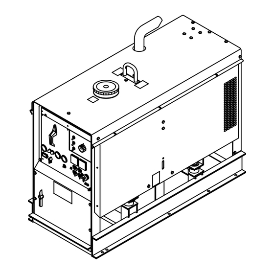
Page 55: Section 10 − Parts List
SECTION 10 − PARTS LIST Fig 10-4 Fig 10-3 Figure 10-1. Main Assembly OM-479 Page 52... - Page 56 Fig 10-2 ST-126 182-F OM-479 Page 53...
- Page 57 Item Dia. Part Description Quantity Mkgs. Figure 10-1. Main Assembly ..... 134 771 PLUG, protective .640sq ........
- Page 58 Item Dia. Part Description Quantity Mkgs. Figure 10-1. Main Assembly (Continued) ..... 123 042 ENGINE, Duetz diesel electric ........
- Page 59 Item Dia. Part Description Quantity Mkgs. Figure 10-1. Main Assembly (Continued) ♦042 420 ..... . SELECTOR SWITCH, plrt and AC (consisting of) .
- Page 60 Item Part Description Quantity Figure 10-2. Generator (Fig 10-1 Item 68) ....173 066 . . . BRACKET, mtg brushholder ........
- Page 61 SC-126 247-A Figure 10-3. Panel, Front w/Components OM-479 Page 58...
- Page 62 Item Dia. Part Description Quantity Mkgs. Figure 10-3. Panel, Front w/Components (Fig 10-1 Item 102) ....010 647 . . . PIN, spring CS .156 x 1.250 .
- Page 63 Item Dia. Part Description Quantity Mkgs. Figure 10-4. Terminal Assembly, Pwr Output (Fig 10-1 Item 105) ..... 108 127 BRACKET, mounting terminal pwr output .
- Page 64 Item Part Description Quantity Figure 10-5. Switch, Range (Fig 10-3 Item 9) 114 193 ....114 235 . . . BRACKET, mounting switch (consisting of) ......
- Page 65 Item Dia. Part Description Quantity Mkgs. Figure 10-6. Control Box w/Components (Fig 10-3 Item 10) ... . . 044 588 . . . RELAY, encl 12VDC 3PDT 10A 120VAC ......♦130 515 .
- Page 66 Dia. Part Description Quantity Mkgs Optional Equipment ....042 320 . . . STARTING AID KIT, diesel (consisting of) ......
-
Page 67: Options And Accessories
Optional polarity switches (below) high-impact plastic panel covers may also be ordered. CV-3 is ideal controls. (Padlock not included). ENGINE METER KIT for use with Miller 115V and 24V (#042 334 Factory) STARTING AID KIT wire feeders. (#042 335 Field) -
Page 68: Ground Fault Circuit Interrupters
OPTIONS AND ACCESSORIES FTC-14 REMOTE CONTACTOR TRAILERS FENDER AND LIGHT KIT AND CURRENT CONTROL For 84X Trailer EDT 2400-2 TWO-WHEEL (#129 338) (#042 198) TRAILER Fastens to TIG torch handle. Includes fenders and 12 Volt light (#041 722) Includes 28 ft. (8.5 m) cord and set.
Need help?
Do you have a question about the Big 30A Diesel and is the answer not in the manual?
Questions and answers