Advertisement
- 1 INTRODUCTION
- 2 BOILER CONTROLS
- 3 TO LIGHT THE BOILER
- 4 OPERATION
- 5 ESCAPE OF GAS
- 6 CLEANING
- 7 MAINTENANCE
- 8 CARBON MONOXIDE ALARMS
- 9 POINTS FOR THE BOILER USER
-
10
FAULT FINDING
- 10.1 Hot water works OK but no central heating
- 10.2 Blank boiler display
- 10.3 Central Heating flow temperature setpoint cannot be increased to 80ºC
- 10.4 Too many restarts
- 10.5 DISPLAY FUNCTIONS (WITHOUT OUTSIDE SENOR)
- 10.6 DISPLAY MESSAGES (WITH OUTSIDE SENSOR)
- 10.7 DISPLAY MESSAGES (GENERAL)
- 10.8 CHANGE SETTINGS (BASIC)
- 10.9 MENU OPERATION
- 11 Documents / Resources
INTRODUCTION
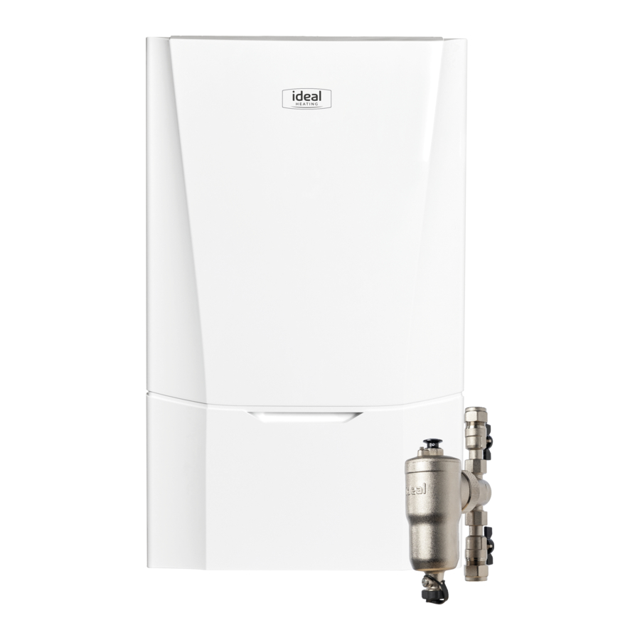
VOGUE MAX SYSTEM
Natural Gas only
| 15 | G.C. Appliance No. | 41-796-22 |
| 18 | G.C. Appliance No. | 41-796-23 |
| 26 | G.C. Appliance No. | 41-796-24 |
| 32 | G.C. Appliance No. | 41-796-25 |
All Gas Safe Register installers carry a Gas Safe Register ID card, and have a registration number. Both should be recorded in the Benchmark Commissioning Checklist. You can check your installer by calling Gas Safe Register direct on 0800 4085500.
FOR ANY QUERIES PLEASE RING THE IDEAL CONSUMER HELPLINE: 01482 498660
 NOTE. BOILER RESTART PROCEDURE -
To restart the boiler, press "RESTART" hot key located below the colour screen. The appliance will now repeat the ignition sequence if a heat demand is present.
The Vogue is a wall mounted, room sealed, condensing system boiler, featuring full sequence automatic spark ignition and fan assisted combustion.
Due to the high efficiency of the boiler, condensate is produced from the flue gases and this is drained to a suitable disposal point through a plastic waste pipe at the base of the boiler. A condensate 'plume' will also be visible at the flue terminal.
SAFETY
Current Gas Safety (Installation & Use) Regulations or rules in force.
In your own interest, and that of safety, it is the law that this boiler must be installed by a Gas Safe Registered Engineer, in accordance with the above regulations.
In IE, the installation must be carried out by a Registered Gas Installer (RGII) and installed in accordance with the current edition of I.S. 813 "Domestic Gas Installations", the current Building Regulations and reference should be made to the current ETCI rules for electrical installation.
It is essential that the instructions in this booklet are strictly followed, for safe and economical operation of the boiler.
IMPORTANT NOTES
- This appliance must not be operated without the casing correctly fitted and forming an adequate seal.
- If the boiler is installed in a compartment then the compartment MUST NOT be used for storage purposes.
- If it is known or suspected that a fault exists on the boiler then it MUST NOT BE USED until the fault has been corrected by a Gas Safe Registered Engineer or in IE a Registered Gas Installer (RGII).
- Under NO circumstances should any of the sealed components on this appliance be used incorrectly or tampered with.
- This appliance is not intended for use by persons (including children) with reduced physical, sensory or mental capabilities, or lack of experience and knowledge, unless they have been given supervision or instructions concerning use of the appliance by a person responsible for their safety.
- Children should be supervised to ensure that they do not play with the appliance.
In cases of repeated or continuous shutdown a Gas Safe Registered Engineer or in IE a Registered Gas Installer (RGII) should be called to investigate and rectify the condition causing this and carry out an operational test. Only the manufacturer's original parts should be used for replacement.
MINIMUM CLEARANCES
Clearances of 165mm above, 100mm below, 2.5mm at the sides. The minimum front clearance when built in to a cupboard is 5mm from the cupboard door but 450mm overall clearance is still required, with the cupboard door open, to allow for servicing.
Bottom clearance
Bottom clearance after installation can be reduced to 5mm.
This must be obtained with an easily removable panel to provide the 100mm clearance required for servicing.
BOILER CONTROLS

Legend
- Boiler Status
- Burner On indication
- Hot Keys
- Central Heating Temp. Control
- On / Off Control
- Pressure Gauge
- Hot Key Identification Text
- Central Heating Status
TO LIGHT THE BOILER
(REFER TO BOILER CONTROLS)
- Switch ON electricity to the boiler and check that all external controls, e.g. programmer and room thermostat, are ON.
- Set the Central Heating temperature control (D) to 'max'.
- Set "off/on" control (E) to "on".
The boiler will commence the ignition sequence supplying heat, if required.
Note. In normal operation the boiler colour screen will display the boiler operation mode.
Boiler frost protection - boiler will fire if temperature is less than 5 degrees C.
During normal operation the burner on indicator (B) will remain illuminated when the burner is lit.
If the boiler has not lit, after 5 ignition attempts, the following screen will be displayed.

Reset the boiler and the ignition sequence will be repeated.
OPERATION
Central Heating
With the external heating controls calling for heat, the "off/on" control (E) set to 'on' and the Central Heating Temperature Control (D) turned fully clockwise, the boiler will operate to provide heat to the system. Note this will also provide heat to the hot water system whose temperature will be controlled by the independent cylinder thermostat.
When the cylinder thermostat is satisfied the system valves will operate to direct all flow to the Central Heating circuit. If the cylinder thermostat calls for heat the system valves will operate to circulate hot water around the cylinder to heat the stored water.
Note. If the pump has not operated in the last 24 hours it will run briefly to ensure it does not become seized.
The boiler controls the central heating radiator temperature to a maximum of 80oC, adjustable via the Central Heating temperature control (D).
| Central Heating Knob Setting | Flow Temp |
| Minimum | 30ºC |
| Maximum | 80ºC |
WEATHER COMPENSATION
When the Weather Compensation option is fitted to the system then the Central Heating Temperature Control (D) becomes a method of controlling room temperature. Turn the Central Heating Temperature Control knob (D) clockwise to increase room temperature and anti-clockwise to decrease room temperature. Once the desired setting has been achieved, leave the knob in this position and the system will automatically achieve the desired room temperature for all outside weather conditions.
TO SHUT DOWN THE BOILER
Set the off/on switch (E) to "off".
TO RESTART THE BOILER
Repeat the procedure detailed in 'To light the boiler'. Set the off/on control to 'on' and set the temperature control to between 30ºC & 80ºC, referring to colour screen whilst adjusting.
FROST PROTECTION
If no frost protection is provided and frost is likely during a short absence from home, leave the heating controls at a reduced temperature setting. For longer periods, the entire system should be drained.
If the system includes a frost thermostat then the timer can be left off. The mains supply should be left switched ON, with the boiler thermostat left in the normal running position.
BOILER OVERHEAT PROTECTION
The boiler controls will shut down the boiler in the event of overheating. Should this occur, the following screen will display:

LOSS OF SYSTEM WATER PRESSURE
The gauge (F) indicates the central heating system pressure. If the pressure is seen to fall below the original installation pressure of 1.0 & 1.5 bar and the below screen is displayed then conduct the re-pressurising procedure as follows:
Re-pressurise via the filling loop to between 1.0 & 1.5 bar (if unsure contact your installer), turn off the tap on the filling loop. Press "RESTART" hot key on the control panel to restart the boiler. If unable to do so or if the pressure continues to drop a Gas Safe Registered Engineer or in IE a Registered Gas Installer (RGII) should be consulted.
THE BOILER WILL NOT OPERATE IF THE PRESSURE HAS REDUCED TO LESS THAN 0.5 BAR UNDER THIS CONDITION.
In this case the following display will appear:

CONDENSATE DRAIN
This appliance is fitted with a siphonic condensate trap system that reduces the risk of the appliance condensate from freezing. However should the condensate pipe to this appliance freeze, please follow these instructions:
- If you do not feel competent to carry out the defrosting instructions below please call your local Gas Safe Registered installer for assistance or in IE a Registered Gas Installer (RGII).
- If you do feel competent to carry out the following instructions please do so with care when handling hot utensils. Do not attempt to thaw a condensate drain pipe if you cannot reach it from ground level. Be aware that any water used can quickly freeze if it falls onto pathways, causing a possible slip hazard. If this appliance develops a blockage in its condensate pipe, its condensate will build up to a point where the burner will go out:
![]()

If the appliance is restarted it will not light prior to it locking out, displaying the above.
To unblock a frozen condensate pipe;
- Follow the routing of the plastic pipe from its exit point on the appliance, through its route to its termination point. Locate the frozen blockage. It is likely that the pipe is frozen at the most exposed point external to the building or where there is some obstruction to flow. This could be at the open end of the pipe, at a bend or elbow, or where there is a dip in the pipe in which condensate can collect. The location of the blockage should be identified as closely as possible before taking further action.
- Apply a hot water bottle, microwaveable heat pack or a warm damp cloth to the frozen blockage area. Several applications may have to be made before it fully defrosts. Warm water can also be poured onto the pipe from a watering can or similar. DO NOT use boiling water.
- Caution when using warm water as this may freeze and cause other localised hazards.
- Once the blockage is removed and the condensate can flow freely, restart the appliance. (Refer to "To Light the boiler")
- If the appliance fails to ignite, call your Gas Safe Registered engineer.
Preventative solutions
During cold weather, set the boiler stat to maximum, (remember to return to original setting once cold spell is over).
Place the heating on continuous and turn the room stat down to 15ºC overnight or when unoccupied (return to normal after cold spell).
ESCAPE OF GAS
Should a gas leak or fault be suspected contact the National Gas Emergency Service without delay. Tel. 0800 111 999
DO NOT SEARCH FOR GAS LEAKS WITH A NAKED FLAME.
CLEANING
For normal cleaning simply dust with a dry cloth. To remove stubborn marks and stains, wipe with a damp cloth and finish off with a dry cloth. DO NOT use abrasive cleaning materials.
MAINTENANCE
The appliance should be serviced at least once a year by a Gas Safe Registered Engineer or in IE a Registered Gas Installer (RGII).
CARBON MONOXIDE ALARMS
Carbon monoxide detectors are installed near to the boiler to detect a gas leak. If a leak is detected the alarm will make a very loud noise. If you suspect that there is a fault with the alarm, you should first change the batteries.
If you change the batteries and the fault does not clear, you must speak to your landlord or replace the device with another that complies to BS EN 50291-1:2010.
POINTS FOR THE BOILER USER
Note. In line with our current warranty policy we would ask that you check through the following guide to identify any problems external to the boiler prior to requesting a service engineer's visit. Should the problem be found to be other than with the appliance we reserve the right to levy a charge for the visit, or for any pre-arranged visit where access is not gained by the engineer.
FAULT FINDING
If a fault occurs then a fault description and suggested potential corrective actions will be displayed. In addition the following information may be useful.
Hot water works OK but no central heating | Ensure that the timer and Room Stat are switched on. Check batteries in programmable room stats. |
Blank boiler display | Ensure that the mains supply to the boiler is switched on and that no trips have operated in the consumer unit. |
Central Heating flow temperature setpoint cannot be increased to 80ºC | Ensure that the CH flow temperature is not limited within the menu (See Change Settings) |
Too many restarts | 5 boiler faults have been reset within a 15 min period. It is recommended that the boiler should be examined by a suitably qualified service engineer. To clear the message turn power off and on. |
DISPLAY FUNCTIONS (WITHOUT OUTSIDE SENOR)
Indicates that the Boiler is Switched Off with frost protection active. Indicates that the boiler is either heating the radiators or Move off/on switch to the "on" position to switch the boiler on. the hot water cylinder.

Indicates that either the timer is off or the room stat and cylinder stats are satisfied.

DISPLAY MESSAGES (WITH OUTSIDE SENSOR)
Indicates that the boiler is switched off. Move off/on switch (E) to the "on" position to switch the boiler on.

Indicates that boiler is heating the hot water cylinder to 60ºC
Boiler is providing central heating and radiator temp is 60ºC.

Indicates that hot water timer or cylinder stat is off
Indicates that central heating timer or room stat is off with an outside temperature of 15°C.

DISPLAY MESSAGES (GENERAL)
Indicates that the temperature at the boiler has been less than 5ºC and the boiler is running to protect itself from frost damage.

Indicates that a service is due.

CHANGE SETTINGS (BASIC)
To change the maximum boiler temperature, rotate the boiler temperature control (D). This screen will be shown:

To disable Central Heating turn the On/Off switch (E) to the Off position. This screen will be shown:

To switch the boiler on, turn the On/Off switch into the On position (E). This screen will be shown:

To change the Room Temperature Set Point (only if outside sensor connected) rotate the boiler temperature control (D). This screen will be shown:

MENU OPERATION
Efficiency Level
To view the efficiency level of the boiler press MENU and the following screen will be displayed;

Press select and a screen similar to the following will be displayed;

Press EXIT twice to return to normal operation.
Reset Service Time
If the boiler has not been serviced within the last 12 months, a message will be displayed indicating this.
To reset the timing of this message, following a boiler service press MENU and the following screen will be displayed;

Press until the following screen is displayed;

Press SELECT and the following screen is displayed;

Press  until the desired number of days required.
Press SET.
Press EXIT to return to normal operation.
Note: Ideal Heating recommend you have your boiler serviced Annually.
Technical Training
Our Expert Academy offer a range of training options designed and delivered by our experts in heating. For details please contact: expert-academy.co.uk
Registered Office
Ideal Boilers Ltd., National Avenue, Hull, East Yorkshire, HU5 4JB
Tel 01482 492251
Fax 01482 448858
Registration No. London 322 137
EU Authorised Representative:
Atlantic SFDT
44 Boulevard des Etats-Unis, 85 000 La Roche-Sur-Yon, France +33 (0)2 51 44 34 34
Ideal Technical Helpline: 01482 498663
Ideal Consumer Helpline: 01482 498660
Ideal Parts: 01482 498665
Documents / Resources
References
Download manual
Here you can download full pdf version of manual, it may contain additional safety instructions, warranty information, FCC rules, etc.
Download IDEAL Vogue MAX System 15 / 18 / 26 / 32 - Boiler Manual
Advertisement


Need help?
Do you have a question about the Vogue MAX System 15 and is the answer not in the manual?
Questions and answers