Advertisement
Introduction
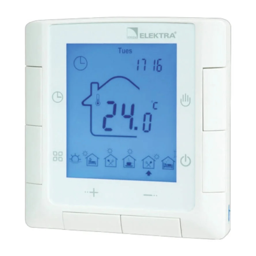
LCD Digital Temperature Controller allows users to select operation mode between manual and energy-saving control. It can be applied to electric heating control.
| Model | Max. load | Control Method |
| ELR-20 | 16A | Controlled by two sensors. Temperature control and limitation. |
Characteristics
- Simple and fast installation
- LCD display with a big screen
- Low energy consumption
- Weekly programming
- Quick temperature setting
Technical Data
Voltage: AC230V 50Hz
Standby power consumption: < 1W
Terminal Blocks: One terminal can be connected to 2*1.5mm² or 1*2.5mm² wire at most
Temperature Range: 5÷90°C
Limit Temperature Range: 16÷60°C
Ambient Temperature Range: -10÷55°C
Protection Class: IP20
Display Interface and User Settings

- ON/OFF
Press key![]() to switch ON/OFF.
to switch ON/OFF. - Temperature setting
Press key![]() to increase the value and press key
to increase the value and press key ![]() to decrease the value.
to decrease the value. - Operation mode selection
Press key![]() to switch between Manual and Auto mode.
to switch between Manual and Auto mode. - Quick setting function
Press key![]() to quickly set the temperature. If the controller is currently in the Auto mode, it enters the Temporary mode.
to quickly set the temperature. If the controller is currently in the Auto mode, it enters the Temporary mode. - Auto mode programming
Hold key![]() for at least 5s to enter programming menu.
for at least 5s to enter programming menu. - Time setting function
Hold key![]() to adjust time and day of the week.
to adjust time and day of the week. - Lock key
Hold key![]() and
and ![]() for 5 seconds to lock the controller. Use the same method to unlock the device.
for 5 seconds to lock the controller. Use the same method to unlock the device.
 to switch ON/OFF.
 to decrease the value.
Advanced Settings
These settings should be applied by authorized installers. The settings are usually completed at the initial installation. Press keys  ,
,  and
and  together when the controller is switched off then switch it on to enter Advanced Settings. Press key to switch between menus. Press key to exit current operating mode.
| No. | Symbol | Function | Adjust by key + or – |
| 1 |  | Temperature calibration | Temperature adjustment |
| 2 |  | Sensor mode selection | IN: air (Default), OUT: floor, ALL: thermostat is controlled by the built-in air sensor but limited by the floor sensor |
| 3 |  | Floor temperature limitation setting | 16÷60°C |
| 4 |  | Difference/Hysteresis | 0.5÷10°C |
| 5 |  | Anti-freeze function ON/OFF When the controller is OFF | The setting range for switching on is 5÷10°C |
| 6 |  | Set the upper limit for temperature | The setting range is 5÷90°C |
| 7 |  | Weekend days selection and weekly programming OFF | Single day off, two days off, no weekend and close weekly program |
| 8 |  | Quick temperature setting value | Maximum value: the highest set temperature; Minimum value: 5°C |
| 9 |  | ON/OFF status selection | ON: Controller maintains the same status when power is off and on again OFF: Controller is in switched-off status when power is off and on again (Default) |
| 10 |  | Restore to factory settings | Hold key  for 5 seconds for 5 seconds |
Operating Mode Introduction
Manual Mode
Operating according to the manually set temperature. Completely out of time programming mode control.
Auto Mode
Weekly programming. You can set 6 events and corresponding temperature for every day in auto mode. Events, temperature, weekend days can be programmed upon the customers' request.
 Temporary Mode
The controller is temporarily out of Auto mode control and switched to Manual mode control status. Automatically restore to Auto mode when the next event comes.
Sensor Malfunction: ER1 display symbol means the built-in air sensor malfunction, ER0-floor sensor malfunction.
Event Programming
Hold key for at least 5 seconds to enter the programming mode.
| Option | Event | Symbol | Default Time | Change | Default Temperature | Change | |
 | Work Days | 1 |  | 06:00 |  Change event time | 20°C | Change temperature |
| 2 |  | 08:00 | 15°C | ||||
| 3 |  | 11:30 | 15°C | ||||
| 4 |  | 12:30 | 15°C | ||||
| 5 |  | 17:00 | 22°C | ||||
| 6 |  | 22:00 | 15°C | ||||
| Weekend | 1 |  | 08:00 | 22°C | |||
| 2 |  | 22:00 | 15°C | ||||
External Dimensions
Unit: mm

Installation Diagram
- Put a flat-blade screwdriver into the two slots on the both sides of the controller then slide out the plugs.

- Remove the metal bracket on the back of the controller by slightly pushing down.

- Fix the metal bracket to the installation box with screws then connect wires correctly according to the wiring diagram.

- Slide the controller into the metal bracket after the wiring is completed. Push the two plugs back in to finish the installation.


Installation Notes
- Power must be off during installation.
- Please connect the wires correctly according to the wiring diagram.
- Recommended installation height: 1.4m, or the same level as other wall switches.
- Do not install the controller in a non-ventilated position. For example in the corner, behind the door.
- Do not install controller in a place with strong airflow and near cold or heat source.
- Prevent small elements or water from entering the temperature controller, as it would cause damage to the controller.
Wiring Connection Diagram

Note:
This controller can be used in full load operation in a place where the altitude is not higher than 2500m. For installations between 2500m and 4200m the max. external load should not exceed 80% of the rated power.
ELEKTRA
K.Kaminskiego 4
05-850 Ozarow Mazowiecki
Poland
tel. +48 22 843 32 82
office@elektra.eu
www.elektra.eu
Documents / ResourcesDownload manual
Here you can download full pdf version of manual, it may contain additional safety instructions, warranty information, FCC rules, etc.
Download ELEKTRA ELR-20 - LCD Digital Temperature Controller Manual
Advertisement


Need help?
Do you have a question about the ELR-20 and is the answer not in the manual?
Questions and answers