Advertisement
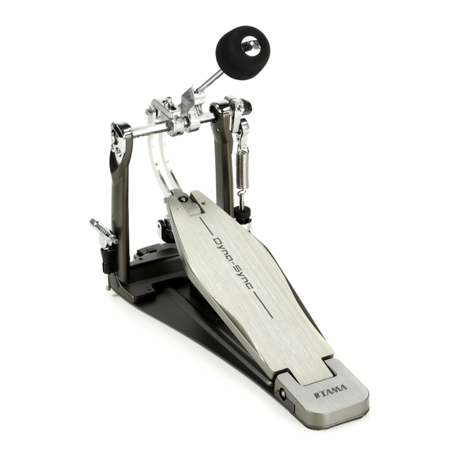
Part Names

- Beater (Dyna-Beater)
- Speedo-Ring
- Quick Hook
- Angle Memory Cap
- Hoop Clamp (Para-Clamp Pro)
- Spring
- Sync-Coil
- Footboard
- Drum Hammer
- Connecting Rod
Assembly
Spring Hook (Quick Hook)
Fit the Quick Hook (c) onto the Speedo-Ring's (b) bearing. If using a twin pedal, repeat this step on the left side spring.
Connecting Rod (Only for Twin Pedal)
Attach the Connecting Rod (j) to the left and right pedal cam shafts. To the right pedal (as seen by the player), attach the cam shaft so that the square headed bolts (5) at the end of the Connecting Rod are positioned as shown in Fig.3-R, and use the Drum Hammer to tighten the bolts. In the same way, fasten the rod to the cam shaft for the left pedal (Fig.3-L). When the assembly is done, adjust the distance between the left and right pedals. Loosen the square headed bolts (6) with a Drum Hammer, and adjust the Connecting Rod to a desired length. Once the desired position is determined, tighten the square headed bolts (6) to secure it.

Hoop Clamp
Adjust the Hoop Clamp opening by turning nut (1).
Adjust as necessary to match the thickness of the bass drum hoop. Then loosen the T-bolt (2) and set the pedal onto the drum hoop. Then retighten the T-bolt.

Beater
To adjust the length of the beater: loosen square headed bolt (3), move the beater head as necessary, and the retighten the bolt (Fig.1).
Adjusting the Beater Angle
The angle of the Beater can be adjusted along with the angle of the footboard by loosening the bolt (4) on side of the Speedo-Ring. You may test the gradations of the Angle Memory Cap, attached to the end of the shaft (The longer line on Angle Memory Cap shows the factory set-up position), by adjusting it a bit at a time (Fig.4-R).
If using a Twin Pedal, repeat this step for the left beater (Fig.4-L).
Once the desired angle is reached, keep the Speedo-Ring in contact with the Angle Memory Cap and tighten the bolt (4) firmly to secure it (Fig.4-R & 4-L).
Adjusting the angle of the beater changes the angle of the cam at the same time.
As the beater moves away from the bass drum head, the angle of the cam rises (Fig.4).
The angle of the cam affects the feel and action of the direct drive pedal. Therefore, when using a twin pedal, we recommend matching the angles of both beaters in the same above mentioned way. Do not adjust the angle of the left beater by loosening the bolt (7) on the beater holder, as doing so may cause the right and left pedal cam angles to be mismatched.

Adjusting the Footboard Angle
After fixing the beater angle, the angle of the footboard can be adjusted independently.
To adjust the footboard angle, loosen the square headed bolt (8) on the front end of the footboard (Fig.5). The factory standard position is shown in Fig.5. The highest position is Fig.5-1, and the lowest angle is Fig.5-2.
Once the desired angle is reached, tighten the bolt (8) firmly.

Adjusting turning radius of the cam (Slidable Cam)
The turning radius of the cam can be adjusted freely by loosening the square headed bolt (9). When the turning radius of cam is longer, the feel of the pedal is lighter. When the radius is shorter, the feel of the pedal is heavier and the footboard returns faster. The factory standard position is shown in Fig.6. The shortest position is Fig.6-1 and the longest position is Fig.6-2. Once the desired angle is reached, tighten the bolt (9) firmly.

Note:
When the front side of bass drum is too high off the ground and the cam is in the longest position, the front end of the cam may touch the batter side head.
If this is the case, shorten the bass drum legs until the cam no longer touches the batter side head.
Adjusting the Spring Tension
Adjust the spring tension using the Adjusting nut on the lower end. When adjusting the spring tension, first loosen the lock nut (Fig.7-1), and then turn the adjusting nut while pressing down on the locknut as in Fig.7-2.
Tightening the nut makes the pedal's resistance heavier, but the beater's return time is correspondingly faster.
Once the desired tension is reached, secure it by tightening the locknut as in Fig.7-3.

Sync Coil
The Sync Coil is a spring that assists the return of the foot board, allowing smoother and faster pedal action.
The strength of the spring can be adjusted by shifting its location. Loosen the square headed bolt (10) located on the back of the under plate, and move the spring toward H (Harder Action) to increase the strength of the spring, or toward S (Softer Action) to lighten the strength of the spring (Fig.8). It is also possible to remove the Sync Coil. You can adjust the system as desired to suit your preferred footboard action.

Pedal Anchor
When setup is completed, manually adjust the Pedal Anchor bolts on the left-side pedal as necessary (Fig.9).

Note:
- Please note that the anchors (spikes) can scratch the floor surface. When using the spikes, we recommend placing rug or mat down on the floor.
- Retighten all bolts (1)~(10) before beginning drum play.
Maintenance
- To maintain a smoother action for extended period of time, wipe clean as necessary with a dry cloth. Note that bearings and hinges are lubrication oil-free design and do not require lubrication.
- The fixing screw in the back side of the under plate or fixing bolts of other parts may become loose due to vibration during playing or transport. Please retighten as necessary using the attached wrench or a Phillips head screwdriver.
Documents / Resources
References
Download manual
Here you can download full pdf version of manual, it may contain additional safety instructions, warranty information, FCC rules, etc.
Advertisement


Need help?
Do you have a question about the Dyna-Sync HPDS1 and is the answer not in the manual?
Questions and answers