Advertisement
INTRODUCTION
Here are some of the features that you will come to love about your new M3:
- 2 Line inputs for connecting CD players, samplers, or other line-level devices
- 2 switchable Phono / Line inputs
- 3-band EQ on each input channel
- 3 EQ Kill switches per channel
- 1 microphone input with Gain and Tone controls
- 1 headphone output with Cue Blend slider
- Professional crossfader with slope adjustment and reversible channel assignments
- Master & Record outputs
BOX CONTENTS
- M3
- AC Power Adapter
- Quick start Guide
- Safety & Warranty Information Booklet
REGISTRATION
Please go to http://www.numark.com to register your M3. Registering your product ensures that we can keep you up-to-date with any last-minute product developments and provide you with world-class technical support, should you run into any problems.
GROUND RULES
- Make sure all items listed in the BOX CONTENTS section are included in the box.
- READ SAFETY & WARRANTY INFORMATION BOOKLET BEFORE USING THE PRODUCT.
- Study the connection diagram in this guide.
- Place mixer in an appropriate position for operation.
- Make sure all devices are turned off and all faders and gain knobs are set to "zero."
- Connect all stereo input sources as indicated in the diagram.
- Connect the stereo outputs to power amplifier(s), tape decks, and/or other audio sources.
- Plug all devices into AC power.
- Switch everything on in the following order:
- Audio input sources (i.e. turntables, CD players, etc.)
- Mixer
- Last, any amplifiers or output devices
- When you are done, always reverse this operation by turning off:
- Any amplifiers or output devices
- Mixer
- Last, any audio input devices
CONNECTION DIAGRAM

 Please Note: Channels 1 & 2 can accept line-level devices (i.e. CD players, samplers, line-level turntables) in the PHONO inputs, as long as the corresponding AUX LINE / PHONO switch is set to AUX LINE.
REAR PANEL FEATURES

- AC IN – Use the included power adapter to connect the mixer to a power outlet. While the mixer's power is switched off, plug the power supply into the mixer first, then plug the power supply into a power outlet.
![warning]() Note: The mixer is designed to work with the included AC power supply only. Using an incompatible power supply could damage the unit.
Note: The mixer is designed to work with the included AC power supply only. Using an incompatible power supply could damage the unit. - POWER SWITCH – Turns the mixer on and off. Turn on the mixer after all input devices have been connected and before you turn on amplifiers. Turn off amplifiers before you turn off the mixer.
- LINE INPUTS (RCA) – Connect line-level devices, such as CD players, samplers or audio interfaces, to these inputs.
- PHONO INPUTS (RCA) – Connect your audio sources to these inputs. These inputs can accept both line and phono-level signals. (See #5 below.)
- AUX LINE / PHONO SWITCH – Flip this switch to the appropriate position, depending on the device connected to the PHONO inputs. If you are using phono-level turntables, set this switch to "PHONO" to provide the additional amplification needed for phono-level signals. If using a line-level device, such as a CD player or sampler, set this switch to "LINE".
- GROUNDING TERMINAL – If you are using phono-level turntables with a grounding wire, connect the grounding wire to these terminals. If you experience a low "hum" or "buzz", this could mean that your turntables are not grounded.
![warning]() Note: Some turntables have a grounding wire built into the RCA connection and, therefore, nothing needs to be connected to the grounding terminal.
Note: Some turntables have a grounding wire built into the RCA connection and, therefore, nothing needs to be connected to the grounding terminal. - MASTER OUTPUT (RCA) – Use standard RCA cables to connect this output to a speaker or amplifier system. The level of this output is controlled by the MASTER knob on the top panel.
- RECORD OUTPUT (RCA) – Use standard RCA cables to connect this output to a recording device, such as a CD recorder or tape deck. The level of this output is based upon pre-master levels.
FRONT PANEL FEATURES

- HEADPHONES OUTPUT – Connect your ¼" headphones to this output for cueing and mix monitoring. Headphone output controls are located on the top panel.
- CUE VOLUME – Adjusts the volume level of the headphone output.
- CUE TONE – Adjusts the tone of the headphone audio signal. Turn this knob to the left to emphasize low (bass) frequencies or turn to the right to emphasize high (treble) frequencies.
- CUE SLIDER – Monitors the audio playing on Channels 1 and 2. Sliding to the left plays Channel 1. Sliding to the right plays Channel 2.
- MIC INPUT – Connect a ¼" microphone to this input.
- MIC GAIN – Adjusts the audio level of the microphone signal.
- MIC TONE – Adjusts the tone of the microphone signal. Turn this knob to the left to emphasize low (bass) frequencies or turn to the right to emphasize high (treble) frequencies.
 Tip: If you experience feedback when using a microphone at loud levels, try turning down high frequencies by turning the knob to the left.
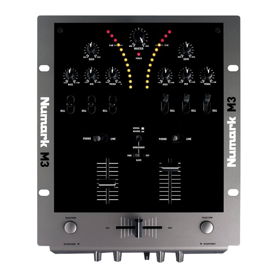
TOP PANEL FEATURES

- POWER LED – Illuminates when the mixer is on.
- MASTER FADER – Adjusts the output volume of the Program mix.
- STEREO LEVEL INDICATOR – Monitors the audio level of the Program mix.
- INPUT SELECTOR – Selects the input source to be routed to the corresponding channel. Input jacks are located on the rear panel.
- CHANNEL GAIN – Adjusts the channel's audio gain level, prefader and pre-EQ.
- CHANNEL BASS – Adjusts the low (bass) frequencies of the corresponding channel.
- CHANNEL MID – Adjusts the midrange frequencies of the corresponding channel.
- CHANNEL TREBLE – Adjusts the high (treble) frequencies of the corresponding channel.
- EQ KILL SWITCHES – Eliminates the bass, mid, or high frequencies of the corresponding channel.
- CHANNEL FADER – Adjusts the audio level of the corresponding channel.
- CROSSFADER – Blends audio between Channels 1 and 2. Sliding the crossfader to the left plays Channel 1. Sliding to the right plays Channel 2.
![warning]() Note: The crossfader is user-replaceable if it should ever wear out. Simply remove the facepanel, then remove the screws holding it in position. Replace the fader with a quality authorized replacement from your local Numark retailer only.
Note: The crossfader is user-replaceable if it should ever wear out. Simply remove the facepanel, then remove the screws holding it in position. Replace the fader with a quality authorized replacement from your local Numark retailer only. - CROSSFADER (CF) SLOPE – Adjusts the slope of the crossfader curve. Flip this switch to the left for a smooth fade (mixing) or to the right for a sharp cut (scratching).
- CROSSFADER (CF) MODE – Press this button to reverse the crossfader assignments of Channels 1 and 2.
- TRANSFORM BUTTONS – Plays only the audio from the corresponding channel when button is held down. Release button to revert back to previous mix.
Documents / Resources
References
Download manual
Here you can download full pdf version of manual, it may contain additional safety instructions, warranty information, FCC rules, etc.
Advertisement


Need help?
Do you have a question about the M3 and is the answer not in the manual?
Questions and answers