Advertisement
- 1 Box Contents
- 2 Support
- 3 Setup
-
4
Features
- 4.1 Top Panel
- 4.2 General Controls
- 4.3 Mixer Controls
- 4.4 Playback Controls
- 4.5 Cue Controls
- 4.6 Pad Mode Controls
- 4.7 Track Controls
- 4.8 Pitch Controls
- 4.9 Navigation Controls
- 4.10 Effects Controls
- 4.11 Displays
- 4.12 Performance View 1
- 4.13 Library View
- 4.14 Performance View 2
- 4.15 Waveform View
- 4.16 Front Panel
- 4.17 Rear Panel
- 5 Videos
- 6 Documents / Resources
Box Contents
NS7III 2 Platter Assemblies
- Aluminum Platter
- Slipmat
- Vinyl
- 45 RPM Adapter (attached)
Spindle Screw
Allen Wrench
Display Unit
Display USB Cable
Display Power Cable Serato DJ™ Software (download)
USB Cable
Power Cable
Quickstart Guide
User Guide (download)
Safety & Warranty Manual
Support
For the latest information about this product (system requirements, compatibility information, etc.) and product registration, visit numark.com.
For additional product support, visit numark.com/support.
Setup
Before getting started:
- Read the Safety & Warranty Manual before using NS7III.
- Make sure all items listed in Introduction > Box Contents are included.
Assemble the Platters
- Remove NS7III from the packaging. Remove the two platter assemblies from package (underneath NS7III). Place NS7III on a flat, stable surface for operation. Ensure unit has adequate air flow to all ventilation ports (especially if installed in a case).
- Place the platter onto NS7III by aligning the pins in the bottom of the platter with the holes in NS7III's motor.

- Place the slipmat onto the platter, then place the vinyl over the slipmat.

- Line up the notch in the spindle with the screw in the vinyl's 45 RPM adapter. Use the allen wrench (included) to tighten the screw, locking the adapter to the spindle.


Attach the Display Unit
- With the screens facing up and slightly toward you, place the display unit over the two brackets on the rear panel (which would typically hold a laptop computer stand). Make sure the two brackets are securely inserted into the holes under the display unit.
- Using the small display USB cable (included), connect the "NS7" USB port on the display unit to the USB port on NS7III's rear panel.
- Using the small display power cable (included), connect the display power input (DC In) to the display power output (DC Out) on NS7III's rear panel.
Install the Drivers and Software
Drivers (Windows users only): Download and install the latest drivers from numark.com.
Software: Download and install the latest version of Serato DJ from serato.com.
Connect and Start DJing!
Follow this sequence of steps whenever you use NS7III:
- Make sure all devices are off and all faders and gain knobs are set to "zero."
- Connect input sources (microphones, turntables, CD players, etc.) to NS7III.
- Connect output devices (headphones, power amplifiers, sub-mixer, recorders, etc.) to NS7III.
- Plug all devices into power sources, and turn on devices in proper order:
- When starting a session, turn on (1) input sources, (2) NS7III and display unit, (3) output devices.
- When ending a session, turn off (1) output devices, (2) NS7III and display unit, (3) input sources.
- Using a standard USB cable (included), connect the "To PC" USB port on NS7III's display unit to your computer.
- Open Serato DJ and go! For more information on how to use Serato DJ with NS7III, visit serato.com/dj/support and select Numark NS7III.
Connection Diagram (example)
")
Any items shown here but not mentioned in Introduction > Box Contents are sold separately.
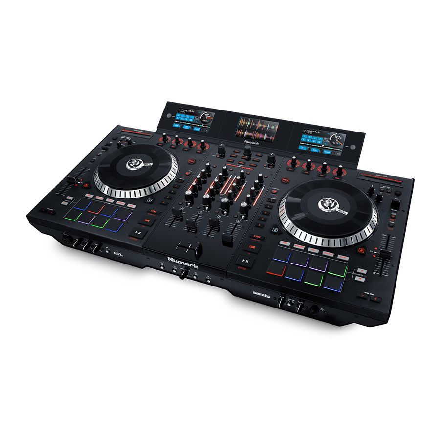
Features
Top Panel

Useful Terms:
Audio Playhead: The current position in a track from where audio will play. When you select a track and begin playing, the Audio Playhead will usually start from the beginning and stop at the end.
Hot Cue Point: A marked position in a track, which will be permanently stored by the software. You can set, return to, or delete Hot Cue Points with the Hot Cue Buttons.
Temporary Cue Point: A marked position in a track, which will only remain while that track is still loaded in the Deck. You can set and return to the Temporary Cue Point with the Cue button.
General Controls
- Displays: Use the screens to view performance information, waveforms, and your library. See Displays for more information.
- View: Press this button to cycle through the available NS7III display modes. See Displays for more information.
- Shift: Press and hold this button to access secondary functions (in red lettering) of other controls on NS7III.
- Touch Mode: Press and hold this button to activate Touch Mode, which lets you access the touch-capacitive functions of NS7III's FX 1 Knob, FX 2 Knob, and FX 3 Knob.
Press and hold Shift and then press this button to access the touch-capacitive functions of the same knobs as above plus the EQ Knobs (Channel Treble, Channel Mid, and Channel Bass). These functions are momentary, not "latching." - Layer: Selects which Layer in the software is controlled by that hardware Deck. Deck A can control Layer 1 or 3; Deck B can control Layer 2 or 4.
- USB Indicator: This LED lights up when NS7III is successfully connected to and communicating with your computer.
Mixer Controls
- Input Selector: Set this switch to the desired audio source from this channel: PC (a track playing on that layer in the software), Mic 2 or Line (a device connected to the Mic 2 Input or Line Input on NS7III's rear panel). Please note that the Line/Phono selector switches on NS7III's rear panel must also be set properly. Also, a channel's controls will only send MIDI information when its Input Selector is set to PC.
![]()
Do not set more than one channel's Input Selectors to Mic2; doing so can cause unwanted feedback or distortion. - Gain Trim: Adjusts the pre-fader, pre-EQ audio level of the corresponding channel in the software.
- LED Meters: Monitors the audio levels of the corresponding channel.
- Channel Treble: Adjusts the high (treble) frequencies. When Touch Mode is activated, touching this knob will mute the corresponding channel's high frequencies (an "EQ kill").
- Channel Mid: Adjusts the mid-range frequencies. When Touch Mode is activated, touching this knob will mute the corresponding channel's mid-range frequencies (an "EQ kill").
- Channel Bass: Adjusts the low (bass) frequencies. When Touch Mode is activated, touching this knob will mute the corresponding channel's low frequencies (an "EQ kill").
- Channel Fader: Adjusts the audio level on the corresponding channel in the software.
- PFL: Press this button to send this channel's pre-fader signal to the Cue Channel for monitoring. When engaged, the button will be lit. By pressing one PFL button at a time, you will cue that channel alone (and deactivate PFL monitoring for the other channels). To cue to multiple channels simultaneously, press the PFL buttons for those channels at the same time.
- Crossfader: Blends audio between the channels assigned to the left and right side of the crossfader.
- Master Volume: Adjusts the output volume of the Program Mix.
- Booth Volume: Adjusts the output volume of the Booth Output mix.

Playback Controls
- Platter: Controls the Audio Playhead in the software.
- Start Time: Controls the rate at which the platter regains its normal playback speed.
- Stop Time: Controls the rate at which the platter slows to a complete stop ("brake time").
- Play /Pause: This button pauses or resumes playback.
Press and hold Shift and then press this button to "stutter-play" the track from the last set Cue Point. - Cue: When the Deck is paused, you can set a Temporary Cue Point by moving the platter to place the Audio Playhead at the desired location and then pressing the Cue Button.
During playback, you can press the Cue Button to return the track to this Temporary Cue Point. (If you did not set a Temporary Cue Point, then it will return to the beginning of the track.)
If the Deck is paused, you can press and hold the Cue Button to play the track from the Temporary Cue Point. Releasing the Cue Button will return the track to the Temporary Cue Point and pause it. To continue playback without returning to the Temporary Cue Point, press and hold the Cue Button, then press and hold the Play Button, and then release both buttons.
Press and hold Shift and then press this button to return to the beginning of the track. - Sync: Press this button to automatically match the corresponding Deck's tempo with the opposite Deck's tempo and phase. Press and hold Shift and press this button to deactivate Sync.
- Bleep /Reverse: Reverses audio playback of the track on the corresponding deck. When the switch is in the Reverse position, the playback of the track will be reversed. Returning the switch to its center (deactivated) position will resume normal playback from wherever the Audio Playhead stops. When the switch is in the Bleep position, the playback of the track will be reversed. Returning the switch to its center (deactivated) position will resume normal playback from where it would have been if you had never engaged the Bleep function (i.e., as if the track had been playing forward the whole time).
Cue Controls
- Hot Cue Buttons (1–5): Assigns a Hot Cue Point or returns the track to that Hot Cue Point. When a Hot Cue Button is unlit, you can assign a Hot Cue Point by pressing it at the desired point in your track. Once it is assigned, the Hot Cue Button will light. To return to that Hot Cue Point, simply press it.
Press and hold Shift and then press a Hot Cue Button to delete its assigned Hot Cue Point.
Tip: If the Deck is paused, holding a lit Hot Cue Button will start playback from that Hot Cue Point. Releasing it will return the track to that Hot Cue Point and pause playback.
Pad Mode Controls
- Pads: These pads have different functions on each Deck depending on the current Pad Mode. These pads are the same pads used with Akai Professional MPCs®, so they are velocity-sensitive (in certain modes only), durable, and easy to play. In this User Guide, when referring to specific pads, it will refer to the numbers as shown here.

- Parameter < />: Use these buttons for various functions in each Pad Mode. Press and hold Shift and use these buttons to access secondary parameters.
- Cues: This Pad Mode button switches the pads between two modes: Hot Cue Mode (red) and Hot Cue Auto-Loop Mode (orange). When the button is unlit, the first press will always select Hot Cue Mode.

- Hot Cue Mode: Each pad assigns a Hot Cue Point or returns the track to that Hot Cue Point. When a pad is unlit, you can assign a Hot Cue Point by pressing it at the desired point in your track. Once it is assigned, the pad will light. Press and hold Shift and then press a pad to delete its assigned Hot Cue Point.
- Hot Cue Auto-Loop Mode: Each pad assigns a Hot Cue Point or returns the track to that Hot Cue Point, but in both cases, it also creates an Auto-Loop at that point. The Auto-Loop's length is set in the software, but you can decrease or increase it with the Parameter < or Parameter > button.


- Auto /Roll: This Pad Mode button puts the pads in two modes: Auto-Loop Mode (dark blue) and Loop Roll Mode (light blue). When the button is unlit, the first press will always select Auto-Loop Mode.
Note: The pad layouts here match the software's default Auto-Loop time division layout. If you shift the range of time divisions displayed in the software, the pad layout will change to match it.
- Auto-Loop Mode: Each pad triggers or releases an Auto-Loop of a different length. Press and hold Shift and then press the Parameter < or Parameter > button to shift the Auto-Loop backward or forward.
- Loop Roll Mode: Each pad triggers a momentary Loop Roll. Press the Parameter < or Parameter > button to change the Loop Roll's time division.


- Loop: This Pad Mode button switches the pads between two banks of saved loops and loop controls. When the button is unlit, the first press will always select the first bank.
- Saved Loop Mode: Pads 1-4 (the top row) return the track to one of your saved loops. You create and save a loop using Pads 5-8 (the bottom row). The pad layouts for the two banks are identical.
- To create a loop, press Pad 5 to set the Loop In Point, and then press Pad 6 to set the Loop Out Point and trigger the loop.
- To save a loop, while a loop is active, press any one of Pads 1-4 (the top row) that does not have a loop assigned to it. You can do this regardless of how the loop was created (Saved Loop Mode, Auto-Loop Mode, Loop Roll Mode, etc.). o To trigger a saved loop, press any one of Pads 1-4 (the top row) that has a loop saved to it. Press Pad 7 to activate or deactivate the loop. Press Pad 8 to return the track to the last triggered loop and reactivate it ("reloop").
- To delete a saved loop, press and hold Shift and then press the corresponding pad (of Pads 1-4).
- To halve or double the length of a loop, press the Parameter < or Parameter > button.
- To shift a loop backward or forward, press and hold Shift and then press the Parameter < or Parameter > button.


- Sampler: This Pad Mode button switches the pads between two modes: Sample Player Mode and Sample Velocity Trigger Mode). When the button is unlit, the first press will always select Sample Player Mode.
- Sample Player Mode: Pads 1-6 each trigger a sample, which you can assign in the software (the volume level is also set in the software). Unlit pads have no sample assigned to them. To stop playback of a sample, press and hold Shift and then press the corresponding pad (of Pads 1-3 or Pads 4-6).
- Sample Velocity Trigger Mode: The pads behave identically to the pads in Sample Player Mode, except they are velocity-sensitive, so triggered samples will play back at a volume level proportional to how heavily you pressed the pads. This mode can give your performance more of a "human feel."


- Slicer: This Pad Mode button switches the pads between two modes: Slicer Mode and Slicer Loop Mode. When the button is unlit, the first press will always select Slicer Mode.
![]()
Your track must have a set Beat Grid for Slicer Mode or Slicer Loop Mode to work.
- Slicer Mode: The eight pads represent eight sequential beats—"Slices"—in the Beat Grid. The currently playing Slice is represented by the currently lit pad; the light will "move through the pads" as it progresses through each eight-Slice phrase. Press a pad to play that Slice—hold it down if you want to keep looping it. When you release the pad, the track will resume normal playback from where it would have been if you had never pressed it (i.e., as if the track had been playing forward the whole time).
Press the Parameter < or Parameter > button to decrease or increase the Slice quantization. Press and hold Shift and then press the Parameter < or Parameter > button to decrease or increase the Slice Domain size. - Slicer Loop Mode: The pads behave identically to the pads in Slicer Mode, except the eight-Slice phrase will loop rather than moving forward continuously through the track.


Track Controls
- Strip Search™: The length of this strip represents the length of the entire track. Place your finger on a point along this sensor to jump to that point in the track. (If you want to scroll through a track, we recommend using your computer rather than running your finger along the strip.)
- Slip /Clear: When using the software's Beat Grid, press and hold this button and move the platter to "slip" (i.e., shift or slide) the entire Beat Grid to the left or right.
Press and hold Shift and then press this button to delete the entire Beat Grid.
![]()
Your track must have a set Beat Grid for the Slip / Clear button to work. - Adjust /Set: Press and hold this button and move the platter to "warp" the entire Beat Grid.
Press and hold Shift and then press this button to set a Beat Marker at the Audio Playhead's current location.
![]()
Your track must have a set Beat Grid for the Adjust feature to work. Also, using the Adjust feature will change the track's BPM. - Slip Mode /Motor Off: Press this button to enable or disable Slip Mode. In Slip Mode, you can jump to Hot Cue Points, trigger Loop Rolls, or use the platters, while the track's timeline continues. In other words, when you stop the action, the track will resume normal playback from where it would have been if you had never done anything (i.e., as if the track had been playing forward the whole time).
Press and hold Shift and press this button to activate or deactivate the corresponding platter's motor. This will not affect the track's playback.
Pitch Controls
- Tap: Tap this button at the same tempo as the track to help the software detect a more accurate BPM reading.
- Range /Master Tempo: Press this to adjust the range of the Pitch Fader to ±8%, ±16%, and ±50%.
Press and hold Shift and then press this button to "lock" the track's pitch to its original key. The track's tempo will remain at the speed designated by the Pitch Fader. - Takeover LEDs: When you select the other Deck with the Deck Select switch, the position of the NS7III's Pitch Fader may not match the Pitch setting for that Deck in the software. Slowly move the Pitch Fader in the direction indicated by the Takeover LED arrow until it turns off. At this point, the Pitch Fader matches the Pitch setting in the software and can control it again.
- Pitch Fader: Controls the track's playback speed. An LED next to the fader will light up when set at 0%.
- Pitch Bend (+ / – ): Press or hold down either of these buttons to temporarily adjust the track's playback speed. When released, the track playback will return to the speed designated by the Pitch Fader.
- BPM Meter: This meter is an aid for matching the tempo of both decks. When the white center LED is lit, the BPMs are matched. Otherwise, the meter will tend towards the faster deck. The further from center, the greater the difference between the two BPMs.
The meter is also an aid while adjusting Loop In or Loop Out points. If you are making fine adjustments to your Loop In or Loop Out points using the platters, the lit LED will "wrap around" the meter. It will rest on the white center LED whenever the loop's length has been doubled or halved exactly.
Note: The BPM Meter will aid in loop adjustments only if (1) a BPM reading has been entered for that track and (2) the two Decks' tempos have been synchronized.
Navigation Controls
- Scroll Knob: Use this knob to scroll through lists of tracks, Crates, etc. in the software. You can also press it to move between the panels shown in the software.
- Fwd / Back: These buttons move the selector between various panels in the software. Press and hold Shift and then press Fwd to sort the current Library/Crate/Panel View by album. Press and hold Shift and then press Back to sort the current Library/Crate/Panel View by track number.
- Crates: Press this to move the selector to the Crates Panel in the software. Press and hold Shift and then press this button to sort the current Library/Crate/Panel View by song.
- Prepare: Press this to move the selector to the Prepare Panel in the software. Press and hold Shift and then press this button to sort the current Library/Crate/Panel View by artist.
- Files: Press this to move the selector to the Files Panel in the software. Press and hold Shift and then press this button to sort the current Library/Crate/Panel View by BPM.
- Load A /Load B: Press one of these buttons while a track is selected to assign it to Deck A or Deck B, respectively.
- Load Prepare: Press this to add a selected track to the list of tracks in the Prepare Panel in the software.
- Panel /View: Press this to toggle through the Recording (Rec), Effects (FX), and Sampler (SP-6) panels. Press and hold Shift and then press this button to toggle through the available software display modes (e.g., Vertical, Horizontal, Extended, Library).
Effects Controls
- FX 1, FX 2, FX 3: These buttons have different functions on each Deck depending on the current FX Mode.
- Single-FX Mode: FX 1 activates or deactivates the effect; FX 2 activates or deactivates the first effect parameter (if applicable); FX 3 activates or deactivates the second effect parameter (if applicable). Press and hold Shift and press FX 1 to select the desired effect. Alternatively, press and hold Shift and then turn the FX Knob under the effect name to move quickly through the list.
- Multi-FX Mode: The buttons activate or deactivate the first, second, and third effects in the effects chain, respectively. Press and hold Shift and press one of the buttons to select the effect for that point in the effects chain. Alternatively, press and hold Shift and then turn the FX Knob under the effect name to move quickly through the list.
- FX 1 Knob, FX 2 Knob, FX 3 Knob: These knobs have different functions on each Deck depending on the current FX Mode.
- Single-FX Mode: the FX 1 Knob controls the "wet-dry" balance of the effect; the FX 2 Knob controls the first effect parameter; the FX 3 Knob controls the second effect parameter. When Touch Mode is activated, touch the FX 1 Knob to activate its effect, and release the knob to deactivate it.
- Multi-FX Mode: The knobs control the "wet-dry" balance of the first, second, and third effects in the effects chain, respectively. When Touch Mode is activated, touch a knob to activate its effect, and release the knob to deactivate it.
- Beat /Mode: Tap this button repeatedly at the desired tempo to set the rate of the effects' low-frequency oscillators (LFOs). Press and hold this button to reset Beat Multiplier to the Deck's BPM. Press and hold Shift and then press this button to switch between Single-FX Mode and Multi-FX Mode.
- Beat Knob: Turn this knob to set the Time Division for the selected effects.
- FX Assign: Use these buttons to apply Effect A and/or B to the corresponding channel. You can apply Effect A and/or B to the entire Program Mix by using the FX Send buttons below the Master Volume knob. (Each effect can be applied to any or all of the four channels and/or the Program Mix.)
- Channel Filter: Turn this knob to adjust the filter on the corresponding channel. The type of filter it adjusts will depend on the Filter Mode button.
- Filter Mode: Press this button to change the Filter Mode (off, Filter Roll Mode, or Filter FX Mode), which affects the Channel Filter knobs.
- Off: When this button is off, the Channel Filter knob will apply and adjust a low-pass filter to the corresponding channel when turned counter-clockwise or a high-pass filter when turned clockwise.
- Filter-Roll Mode: Press this button once to activate Filter-Roll Mode (the button will light solid red). The Channel Filter knob will apply and adjust a low-pass filter to the corresponding channel when turned counter-clockwise or a high-pass filter when turned clockwise. In addition, it will apply a Loop Roll to the filter and will decrease in length as the knob moves further away from the center position. Press this button once to deactivate Filter-Roll Mode.
- Filter-FX Mode: Press and hold Shift and then press this button to activate Filter-FX Mode (the button will flash red). The Channel Filter knob will apply and adjust a lowpass filter to the corresponding channel when turned counter-clockwise or a highpass filter when turned clockwise. In addition, it will adjust Parameter 1 of the effects applied to that channel as the knob moves further away from the center position. Press this button once to deactivate Filter-FX Mode.
Displays
NS7III's full-color displays provide real-time feedback of the software. The left and right displays can show Performance View 1 or Performance View 2. The center display can show Library View or Waveform View.
To switch views, press the View button next to the display on either deck.
To enter Library View immediately, turn the Scroll Knob. After not touching the Scroll Knob for 5 seconds, the display will return to Waveform View.
To load a track to a deck from Library View, press the Load button for the desired deck.
Each view shows the current settings of various controls, which you can adjust as described in the following sections. Click one below to jump to that section.
Performance View 1

Library View

Performance View 2

Waveform View

Performance View 1

This view provides an alternative display of information about the current track, effects, hot cues, and loops.
- Deck: This is the currently selected Layer in the software controlled by that hardware deck. Press the Deck button to switch between the Layers. Deck A controls Layer 1 or 3; Deck B controls Layer 2 or 4.
- Track Name: This is the title the currently loaded track, which will scroll by. See Library View to learn how to select tracks.
- Track Key: This is the key of the currently loaded track. This is the track's key with a 0% pitch adjustment.
- Track BPM: This is the tempo (in beats per minute or BPM) of the currently loaded track with a 0% pitch adjustment. To see the BPM at which it is currently playing, see Deck BPM below.
- Deck BPM: This is the current BPM at which the currently loaded track is playing. To adjust this value, move the deck's Pitch Fader. This number is not affected by temporary pitch bends (using the Pitch Bend -/+ buttons or the platter).
- Remaining Time: This is how much time is left of the currently loaded track.
- Pitch Range: This is the current range of the deck's Pitch Fader. Press Range / Keylock on that deck to adjust the range of its Pitch Fader to +8%, +16%, or +50%.
- Pitch Adjustment: This is the current setting of the Pitch Fader. To adjust this setting, move the deck's Pitch Fader.
- Track Overview: This is the currently loaded track's waveform, which is color-coded according to the frequency of each area: red indicates low (bass) frequencies, green indicated mid-range frequencies, and blue indicates high (treble) frequencies.
In the waveform, hot cue points are represented by triangles at the bottom of the waveform, and loop regions are represented by shaded-blue sections. - Main Waveform: This is the currently playing segment of the track's waveform, which will scroll by as the audio playhead moves through the track. The waveform is color-coded according to the frequency of each area: red indicates low (bass) frequencies, green indicated mid-range frequencies, and blue indicates high (treble) frequencies.
In the waveform, hot cue points are represented by triangles at the top and bottom of the waveform, and loop regions are represented by shaded-blue sections. - Auto-Loop Button: This button is the deck's current auto-loop length. In Auto-Loop Mode, press one of the pads to trigger an auto-loop of a specific length, which will be shown here. See Top Panel > Pad Mode Controls > Auto / Roll to learn more.
- Effect Name: In Multi-FX Mode, the view will show three effects with one parameter knob each.
In Single-FX Mode, the view will show one effect name with three parameter knobs.
To switch between Single-FX Mode and Multi-FX Mode, press and hold Shift and press the Beat button.
To move to the next effect (in either mode), press and hold Shift and then press the FX Button under the effect name. Alternatively, press and hold Shift and then turn the FX Knob under the effect name to move quickly through the list. - Effect Parameter: In Multi-FX Mode, the view will show three effects with one parameter knob each, which corresponds to the main parameter of that effect. To adjust each effect, turn the FX Knob below it.
In Single-FX Mode, the view will show one effect name with three parameter knobs. To adjust each parameter, turn the FX Knob below it.
To switch between Single-FX Mode and Multi-FX Mode, press and hold Shift and press the Beat button. - Effect Beats Multiplier: This number determines the timing or rate of the effects, based on the BPM.
Library View

This view lets you browse through your library, including crates and subcrates, and load a track to either deck.
To move through the list of tracks, turn the Scroll Knob.
To load the currently selected track, press the Load button on the desired deck.
To switch between the track list and crate list, press the Scroll Knob or use the Back / Fwd button.
To expand or collapse a crate (that has subcrates)in the crate list, press the Back / Fwd button.
- Crate/List Name: This is the crate, subcrate, or other track list (e.g., All) that you are currently viewing.
- Track Name: This is the title of the currently loaded track.
- Artist Name: This is the artist of the currently loaded track.
- Track BPM: This is the tempo (in beats per minute or BPM) of the track.
Performance View 2

This view contains information about the current track, effects, hot cues, and loops.
- Deck: This is the currently selected Layer in the software controlled by that hardware deck. Press the Deck button to switch between the Layers. Deck A controls Layer 1 or 3; Deck B controls Layer 2 or 4.
- Track Name: This is the title of the currently loaded track. See Library View to learn how to select tracks.
- Artist Name: This is the artist of the currently loaded track. See Library View to learn how to select tracks.
- Track BPM: This is the tempo (in beats per minute or BPM) of the currently loaded track with a 0% pitch adjustment. To see the BPM at which it is currently playing, see Deck BPM below.
- Track Key: This is the key of the currently loaded track. This is the track's key with a 0% pitch adjustment.
- Deck BPM: This is the current BPM at which the currently loaded track is playing. To adjust this value, move the deck's Pitch Fader. This number is not affected by temporary pitch bends (using the Pitch Bend -/+ buttons or the platter).
- Remaining Time: This is how much time is left of the currently loaded track. The ring around the virtual platter is a visual representation of this value (the complete circle being the entire track).
- Pitch Range: This is the current range of the deck's Pitch Fader. Press Range / Keylock on that deck to adjust the range of its Pitch Fader to +8%, +16%, or +50%.
- Pitch Adjustment: This is the current setting of the Pitch Fader. To adjust this setting, move the deck's Pitch Fader.
- Track Overview: This is the currently loaded track's waveform, which is color-coded according to the frequency of each area: red indicates low (bass) frequencies, green indicated mid-range frequencies, and blue indicates high (treble) frequencies.
In the waveform, hot cue points are represented by triangles at the bottom of the waveform, and loop regions are represented by shaded-blue sections. - Auto-Loop Buttons: These eight buttons correspond to the deck's eight pads while in Auto-Loop Mode. In that mode, press one of the pads to trigger an auto-loop of the corresponding length. See Top Panel > Pad Mode Controls > Auto / Roll to learn more.
- Effect Name: In Multi-FX Mode, the view will show three effects with one parameter knob each.
In Single-FX Mode, the view will show one effect name with three parameter knobs.
To switch between Single-FX Mode and Multi-FX Mode, press and hold Shift and press the Beat button.
To move to the next effect (in either mode), press and hold Shift and then press the FX Button under the effect name. Alternatively, press and hold Shift and then turn the FX Knob under the effect name to move quickly through the list. - Effect Parameter: In Multi-FX Mode, the view will show three effects with one parameter knob each, which corresponds to the main parameter of that effect. To adjust each effect, turn the FX Knob below it.
In Single-FX Mode, the view will show one effect name with three parameter knobs. To adjust each parameter, turn the FX Knob below it.
To switch between Single-FX Mode and Multi-FX Mode, press and hold Shift and press the Beat button. - Effect Beats Multiplier: This number determines the timing or rate of the effects, based on the BPM.
Waveform View

This view contains the currently playing segments of the waveforms on the active decks. To switch which waveform is shown, press the Layer button for each deck. The waveforms will scroll by as the audio playhead moves through the track.
The waveforms are color-coded according to the frequency of each area: red indicates low (bass) frequencies, green indicated mid-range frequencies, and blue indicates high (treble) frequencies.
In each waveform, hot cue points are represented by triangles at the top and bottom of the waveform, and loop regions are represented by shaded-blue sections.
Front Panel

- Headphones (1/4", 1/8") (6.35 mm, 3.5 mm): Connect your 1/4" or 1/8" (6.35 mm or 3.5 mm) headphones to this output for cueing and mix monitoring.
- Headphone Volume: Adjusts the volume level of the headphone output.
- Split Cue: When this switch is in the on position, the headphone audio will be "split" such that all channels sent to Cue are mixed to mono and applied to the left headphone channel and the Program mix is mixed to mono and applied to the right channel. When the switch is in the off position, Cue and Program audio will be "blended" together.
- Cue Blend: Turn to mix between Cue and Program in the Headphone channel. When all the way to the left, only channels routed to Cue will be heard. When all the way to the right, only the Program mix will be heard.
- Crossfader Assign: Routes the audio playing on the corresponding channel to either side of the crossfader (A or B), or bypasses the crossfader and sends the audio directly to the Program Mix (center, Off).
- Crossfader Slope: Adjusts the slope of the crossfader curve. Turn the knob to the left for a smooth fade (mixing) or to the right for a sharp cut (scratching). The center position is a typical setting for club performances.
- Mic 1 Input (1/4" / 6.35 mm): Connect a 1/4" (6.35 mm) microphone to this input. This input's audio signal is routed directly to the Program Mix and Cue Mix.
- Mic 1 On/Off: When set to on, the Mic 1 Input is active, and its audio signal is routed directly to the Program Mix and Cue Mix. When set to off, the Mic 1 Input is disabled.
- Mic Gain: Adjusts the gain of the microphone channel.
- Mic Bass: Adjusts the low (bass) frequencies of the audio signal coming from the microphone input.
- Mic Treble: Adjusts the high (treble) frequencies of the audio signal coming from the microphone input.
Rear Panel

- NS7III Power Input: Use the included power cable to connect NS7III to a power outlet. While the power is switched off, plug the cable into NS7III first, then plug the cable into a power outlet.
- NS7III Power Switch: Powers NS7III on and off. Power on NS7III after all input devices have been connected and before you turn on amplifiers. Turn off amplifiers before you turn off NS7III.
- USB Port: Use the included small display USB cable to connect this USB port to the "NS7" USB port on the display.
- Power Output (DC Out): Use the included small display power cable to connect this output to the display power input (DC In).
- Display Power Input (DC In): Use the included small display power cable to connect this input to the power output (DC Out) on NS7III.
- Cable Restraint: You can secure the display power cable to this restraint to help prevent disconnecting it accidentally.
- Display Power Switch: Powers the display unit on and off.
- USB Port (NS7): Use the included small display USB cable to connect this USB port to the USB port on NS7III.
- USB Port (USB In): You can connect an optional USB hard drive (not included) to this powered USB port.
- Display USB Port (To PC): Use the included USB cable to connect this USB port to your computer.
- Master Output (XLR): Connect this low-impedance XLR output to a PA system or powered monitors. The level of this output is controlled with the Master knob on the top panel.
- Master Output (RCA): Use standard RCA cables to connect this output to a speaker or amplifier system. The level of this output is controlled by the Master knob on the top panel.
- Booth Output (RCA): Use standard RCA cables to connect this output to a booth monitoring system. The level of this output is controlled by the Booth knob on the top panel.
- Line/Phono Inputs (RCA): Connect your audio sources to these inputs. These inputs can accept both line and phono-level signals.
- Line/Phono Switch: Flip this switch to the appropriate position, depending on the device connected to the Line/Phono Inputs. If you are using phono-level turntables, set this switch to Phono to provide the additional amplification needed for phono-level signals. If using a line-level device, such as a CD player or sampler, set this switch to Line.
- Line Inputs (RCA): Connect line-level devices, such as CD players, samplers or audio interfaces, to these inputs.
- Grounding Terminal: If using phono-level turntables with a grounding wire, connect the grounding wire to these terminals. If you experience a low "hum" or "buzz", this could mean that your turntables are not grounded.
Note: Some turntables have a grounding wire built into the RCA connection and, therefore, nothing needs to be connected to the grounding terminal. - Mic 2 Input (1/4" / 6.35 mm): Connect a 1/4" (6.35 mm) microphone to this input. Microphone controls are located on the top panel on any channel whose Input Selector is set to Mic2.
- Motor Torque: Flip this switch to adjust the torque of the platters. At the high setting, the platters will have the heavier, stronger feel of "modern" turntables. At the lower setting, they are lighter and more graceful — the feel of a "classic" turntable.
- Cooling Fan: Keep the area in front of this vent clear from obstructions. The fan behind the vent cools the NS7III, preventing overheating.

VideosNumark NS7III Review Video & Talkthrough
Documents / Resources
References
Download manual
Here you can download full pdf version of manual, it may contain additional safety instructions, warranty information, FCC rules, etc.
Advertisement


Need help?
Do you have a question about the NS7III and is the answer not in the manual?
Questions and answers