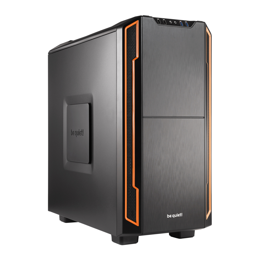
be quiet! Silent Base 600 - PC Cases Manual
- User manual (44 pages) ,
- User manual (46 pages) ,
- User manual (46 pages)
Advertisement
- 1 SPECIFICATIONS
- 2 INSTALLATION PROCESS
-
3
STEP-BY-STEP INSTALLATION
- 3.1 REMOVE THE SIDE PANELS
- 3.2 CHANGING THE DOOR OPENING DIRECTION
- 3.3 OPTIONAL FANS/RADIATOR INSTALLATION
- 3.4 INSTALLATION OF THE MOTHERBOARD
- 3.5 INSTALLATION OF POWER SUPPLY UNIT
- 3.6 INSTALLATION OF A 5.25" DEVICE/ODD
- 3.7 INSTALLATION OF A 3.5" DEVICE / HDD
- 3.8 INSTALLATION OF THE 3-BAY HDD CAGE INTO THE 5.25" BAY
- 3.9 INSTALLATION OF A 2.5" DEVICE/SSD
- 3.10 CLEANING THE AIR FILTERS
- 4 MANUFACTURER'S DETAILS
- 5 Documents / Resources
SPECIFICATIONS
SCOPE OF DELIVERY
- 1 case
- 1 accessory kit box
- 1 manual
Ensure your hardware does not exceed any of the limits listed in the table of specifications, as this could cause damage to the housing or the equipment you install in it. Note that product specifications are subject to change without notice
| Model | Silent Base 600 Orange / Black / Sliver / Red / Green |
| Article number | BG005 (Orange), BG006 (Black), BG007 (Silver), BG008 (Red), BG009 (Green) |
| Material | 07mm SECC, ABS, nylon |
| Case size (L x W x H), (mm) | 495 x 230 x 493 |
| Net weight (kg) | 78 |
| Main board size | Mini-ITX, Micro-ATX, ATX |
| 525" bays | 3 |
| 35" bays | 3 |
| 25" bays | 3 |
| Front I/O ports | USB 30 (2 of), USB 20 (2 of), HD Audio (Microphone and Headset) |
| Front cooling fan | 140mm @900rpm - be quiet! Pure Wings 2 |
| Rear cooling fan | 120mm @1200rpm - be quiet! Pure Wings 2 |
| Optional cooling | 2x 140/120mm (top), 1x 140/120mm (bottom), 1x 140mm (front), 1x 120mm (side panel) |
| PCI slots | 7 |
| Power supply | PS2 ATX, maximum length 300mm |
| CPU cooler height (mm) | 170 max |
| Graphics card length (mm) | 290 (with HDD cage), 400 (HDD cage removed) |
| Liquid cooling system | Front 120/140mm radiator (optional) Rear 120mm radiator (optional) Top 240mm radiator (optional) |
INSTALLATION PROCESS
Before commencing assembly please ensure that all accessories and components are available and in the amount listed
Accessories Pack
| Images | Part Name | Amount | Usage |
 | #6-32 Round head screws | 8 | Secure motherboard |
 | M3 HDD screws | 12 | Secure rubber rail to HDD |
 | M3 x8 Flat head screws #6-32 x 5 Flat head screws | 12 4 | Secure 25" HDD/SSD Secure 2.5" HDD cage tray |
 | M3 x 5 Round head screws | 6 | Secure 525" device/ODD |
 | #6-32 x30 flat head screws | 4 | Secure front intake fan |
 | #6-32 Hex head screws | 4 | PSU |
 | Rubber rail | 6 | Mounting HDD to HDD cage |
 | Standoff | 2 | For motherboard |
 | Cable tie long | 2 | Cable management |
 | Cable tie short | 2 | Cable management |
 | Cable tie holder | 1 | Cable management |
Description of the model

| 1 | Upper front panel | 9 | Front I/O ports |
| 2 | Front air filter | 10 | Optional fan mountings |
| 3 | Intake fans | 11 | Rear exhaust fan |
| 4 | 525" bays/bezels | 12 | 5.25" device lock |
| 5 | Left side panel with fan mounting and filter | 13 | 3-bay HDD cage |
| 6 | Side panel bezel | 14 | 3-step fan controller |
| 7 | Right side panel with filter. NOTE: no optional fan mounting on right side panel NOTE: no optional fan mounting on right side panel | 15 | PCI brackets |
| 8 | Top cover |
Front I/O ports

| 1 | USB 20 |
| 2 | Headphone jack |
| 3 | Microphone jack |
| 4 | USB 30 |
| 5 | Power button/Power LED |
| 6 | HDD LED/reset button |
| 7 | 3-step fan controller |
The function panel has several wire connections that need to be installed
HD audio (headphone jack/microphone jack)

Find the "Front panel audio headers/pin connectors" on the KEY motherboard Plug in the wires according to the motherboard manual
USB 2.0

Find the "USB 20 Headers/pin connectors" on the motherboard
Plug in the wires according to the motherboard manual
USB 3.0

Find the "USB 30 Headers/pin connectors" on the motherboard
Plug in the wires according to the motherboard manual
Power switch, Power LED, HDD LED, Reset switch

These wires plug into the motherboard where all the front panel switch/pin connectors functions are located The motherboard manual will have a description of where to plug these in, usually their location is labeled in the motherboard manual
3-step fan controller

The fan controller is powered by a SATA connector that has to be connected directly to the power supply The controller is able to control up to three 3-pin fans Plug in the 3-pin connector of the fan controller into the plug of your 3-pin fan
STEP-BY-STEP INSTALLATION
It is important you follow all the instructions in the sequence they are given
REMOVE THE SIDE PANELS

Release the thumb screws and slide each side panel backwards to release it from the chassis.
CHANGING THE DOOR OPENING DIRECTION
- Remove the rubber caps and release the door stop screws and the two screws on the hinges to remove the upper door.

- Remove the side panel.

- Remove the front panel

- Remove the screws to release the hinge holder.

- Remove the door hinge

- Re-insert the hinge at the other end, reverse the steps from 1.


OPTIONAL FANS/RADIATOR INSTALLATION
- Before removing the upper cover, first remove the front panel.

- Remove the upper cover and install an additional fan/radiator.

- The fans/radiator can be adjusted for the top cover.

- To install the fan on the bottom of the chassis, remove the bottom air filter and screw the fan from below.

- To mount a radiator or an additional fan at the front, the HDD cage has to be removed.


INSTALLATION OF THE MOTHERBOARD
Install the motherboard's I/O shield first, aligning the motherboard with the standoff in the center of the motherboard tray, secure with the #6-32 flat head screws supplied.

INSTALLATION OF POWER SUPPLY UNIT
Insert the power supply unit at the bottom of the case, secure the PSU with screws

INSTALLATION OF A 5.25" DEVICE/ODD
- Remove the 5.25" bezels by releasing them from inside the case.

- Slide the 5.25" device/ODD into the drive bay. Push the lock backwards to secure it. An extra screw ensures it remains locked.

INSTALLATION OF A 3.5" DEVICE / HDD

Note: the HDD cage is pre-mounted linked to the motherboard tray for extra security If you want to remove the HDD cage, first release the thumb screw at the rear of the motherboard tray
- Install the silicone rubber runners on the 3.5" device/HDD with thumb screws.

- Open the gate on the HDD cage.

- Insert the HDD into the HDD cage.

- Close the gate to secure the HDD inside the HDD cage.


INSTALLATION OF THE 3-BAY HDD CAGE INTO THE 5.25" BAY

Note that when if you use an HDD cage inside the 525" cage, you will not be able to install another 525" device
- Remove the upper HDD holder by releasing the four screws below the 5.25 bay.
![]()
- Install the HDD holder inside the 5.25" bay and secure it with four screws.

- There are two different positions for the HDD holder: Placed flush with the front or more inwards the case ending behind the 5.25" bezels.

- Insert the three 3.5" bays upside down in the 5.25" bay and secure it with the thumb screw.


INSTALLATION OF A 2.5" DEVICE/SSD
To mount the 2.5" device/SSD in the HDD cage, first remove the HDD cage

- Mount the 2.5" device/SSD upside down under the top panel of the HDD cage with M3 flat head screws.

- To mount the 2.5" device/SSD behind the motherboard tray: Remove the 2.5" device/SSD tray from the rear of the motherboard tray. Secure the SSD with M3 flat head screws.


CLEANING THE AIR FILTERS
- Open the front panel and pull the air filter upwards.

- For the air filter on the side panel, pull out the side panel cover to access the air filter.

- For the air filter under the power supply, pull the air filter out from the rear of the case.


MANUFACTURER'S DETAILS
Listan GmbH & Co. KG | Biedenkamp 3a | 21509 Glinde | Germany
For support in Germany, you can call our free service hotline
Monday through Friday 09:00 – 17:30 (UTC+1)
Tel 0049 40 736 7686 - 44 Fax 0049 40-7367686-69
Email: service@bequietcom
Website: www.bequiet.com
Documents / Resources
References
Download manual
Here you can download full pdf version of manual, it may contain additional safety instructions, warranty information, FCC rules, etc.
Advertisement


Need help?
Do you have a question about the Silent Base 600 and is the answer not in the manual?
Questions and answers