
Related Manuals for FujiFilm VISUAL SONICS Vevo F2


Summary of Contents for FujiFilm VISUAL SONICS Vevo F2
- Page 1 Vevo F2 Imaging System User Manual Part Number: 53188 Revision: 1.2 Last Updated: June 2020...
-
Page 2: Legal Notices
9,184,369; 9,520,119; 9,555,443; 9,445,787; 9,474,498; 9,935,254; 9,997,696; D531,316; D541,942. Notice of non-liability: FUJIFILM VisualSonics, Inc. is providing the information in this document to you as is with all faults. FUJIFILM VisualSonics, Inc. makes no warranties of any kind (whether express, implied or statutory) with respect to the information contained herein. -
Page 3: Table Of Contents
Table of Contents Introduction Document Conventions In This User Guide System Overview Vevo F2 Imaging System Vevo LAZR-X Laser Cart Image Display Control Panel Basic Touchscreen Actions Onscreen Keyboard Transducers Accessories Quick Start Guide - B-Mode Before You Begin To Acquire, Analyze and Export a B-Mode Image Quick Start Guide - PA-Mode Before You Begin To Acquire, Analyze and Export a PA-Mode Image... - Page 4 Castors and Handles Vevo Integrated Rail System Vevo Animal Monitoring System Vevo LAZRTight Vevo PHANTOM Imaging Chamber Vevo LAB System Startup To Turn On the Laser Cart Logging On for the First Time To Configure the Administrator Account System Maintenance Cleaning and Disinfecting Moving the System or Laser Disposal System Upgrade...
- Page 5 Physiological Data Troubleshooting License Update To Export Your Machine ID To Update Your System License Session Tasks Logging In Interface Overview Image Display Control Panel Interface (Scanning) Control Panel Interface (Review) List of Imaging Controls Controls and Modes Control Descriptions Common Tasks Change Scanning Modes Change Transducers or Applications Adjust Image...
- Page 6 Measurements Customizing Controls Saving Images Logging Out Modes B-Mode Image Display B-Mode Control Panel Interface B-Mode Controls B-Mode Needle Guide for Injections PA-Mode Before You Begin Staging and Acquisition States PA-Mode Image Display Interface PA-Mode Control Panel Interface PA-Mode Image Acquisition Workflow List of PA Sub-Modes PA Sub-Mode Settings PA-Mode Controls...
- Page 7 Hardware Limitations Transducer Thermal Management VADA Workflow VADA Image Display Interface VADA Control Panel Interface VADA Mode Controls VADA Clip Settings Transducer Settings Panel Speed of Sound Voltage VADA Configuration Panel Settings Transducer Preview Review Study Browser Filtering the List of Studies in the Study Browser Adjusting Study Browser View Working with Studies Creating a Study During an Imaging Session...
- Page 8 Working with Series Creating a New Series Editing a Series Moving a Series Closing a Series Re-opening a Series Deleting a Series View Current Series Working With Images To Open an Image To Name an Image From the Study Browser Modifying a Stored Image Storing an Image Deleting an Image...
- Page 9 Applications & Presets Navigation Transducers, Applications, and Presets Managing Applications Presets Backup and Restore System Backup System Restore Importing, Exporting and Deleting Backup Files Export To Display the Export Page Export Options General To Select the General Tab Institution Startup Date and Time System Sounds Display Brightness Foot Pedal Configuration...
- Page 10 Edit Annotations Network To Display the Network Page Changing Network Settings Configuring Network Drives Photoacoustics To Display the Photoacoustics Page Single Wavelength Bookmarks System Information To Display the System Information Page System Logs To Display the System Logs Page To Export Log Files To Delete Log Files User Management To Open the User Management Settings Page...
- Page 11 Electrical Specifications Vevo LAZR-X Laser Cart Specifications Label Information System Labels Vevo LAZR-X Laser Cart Labels Safety Information Vevo F2 Imaging System Safety Laser Safety Compliance Information Vevo F2 Imaging System Vevo LAZR-X laser cart Contact and Legal Information FUJIFILM VisualSonics...
- Page 12 Document Information Support Start Remote Help Session...
-
Page 13: Introduction
This guide is written for users who are familiar with ultrasound, and does not provide training in sonography. Before using the Vevo F2 Imaging System, in-depth training from an experienced user, such as a FUJIFILM VisualSonics Applications Specialist, is recommended. -
Page 14: System Overview
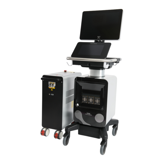
Vevo F2 Imaging System User Manual System Overview Vevo F2 Imaging System The Vevo F2 Imaging System is an ultrasound system. It consists of the following major components: The top screen is the image display, which displays imaging data. The bottom screen is the touchscreen control panel, which serves as the control surface for the system. -
Page 15: Image Display
Vevo F2 Imaging System User Manual Laser cart Both the ultrasound unit and laser cart are on castors for easy transportation. Image Display The image display is the top monitor of the Vevo F2, and primarily displays imaging data. Introduction... -
Page 16: Control Panel
Vevo F2 Imaging System User Manual The image display when the system is in B-Mode While the image display varies slightly depending on the current imaging mode, it always displays several categories of data: Experiment information: Contains information such as the name of the experiment (entered by the user), the imaging mode, and the transducer currently in use. -
Page 17: Basic Touchscreen Actions
Vevo F2 Imaging System User Manual The control panel The control panel contains the following features: A top bar that navigates between menus within the Vevo F2 software. A working area that contains image adjustment controls for the currently selected imaging mode. A collection of control buttons that carry out one of the following functions: Selects an imaging mode Opens features of the currently selected imaging mode... -
Page 18: Onscreen Keyboard
Vevo F2 Imaging System User Manual Gesture Description Associated Actions Adjust depth or gain Touch the screen with a Move PA-Mode box finger, and while continuously Move measurement calipers touching, drag the finger Pan image in zoom area Drag across the screen before Move through frames in a clip lifting away. - Page 19 Vevo F2 Imaging System User Manual Onscreen keyboard 1. Alpha keys: Tap and hold the alpha keys to reveal options for selecting accented versions of the characters. 2. Shift key: Changes alphabet keys to between uppercase and lowercase letters. 3. Number/Alpha toggle: Changes between the alpha and number keyboards. 4.
-
Page 20: Transducers
Vevo F2 Imaging System User Manual To Enable Caps Lock 1. Tap a text box (for example, the study name) to open the onscreen keyboard. 2. Tap the shift key twice until the arrow becomes solid green. 3. To disable caps lock, tap the shift key again until it shows the clear arrow. Transducers Caution: Only compatible transducers may be used with the Vevo F2 Imaging... -
Page 21: Accessories
Vevo F2 Imaging System User Manual Coupling Gels When using coupling gels, use Aquasonic® 100 Ultrasound Transmission Gel, or a gel with similar properties. Accessories Note: This page only covers accessories that are specific to the Vevo F2 Imaging System. It does not include common items used with all ultrasound devices, such as coupling creams or gels. -
Page 22: Quick Start Guide - B-Mode
Vevo F2 Imaging System User Manual Quick Start Guide - B-Mode This tutorial provides a high-level overview for acquiring, analyzing, and exporting a B-Mode image. For more information about imaging sessions, refer to Session Tasks on page 78. Before You Begin Ensure the following: A transducer is connected to a transducer port on the front of the Vevo F2. - Page 23 Vevo F2 Imaging System User Manual Measurements on page 111. d. Once the measurement appears, place the measurement by dragging the calipers. e. When you are done, tap Save Clip to save your image. 10. View a report, if desired. a. Navigate to either the Current Series or the Study Browser menu. b.
-
Page 24: Quick Start Guide - Pa-Mode
Vevo F2 Imaging System User Manual Quick Start Guide - PA-Mode This tutorial provides a high-level overview for acquiring and analyzing a PA-Mode image and then exporting your data. Note: PA-Mode (Photoacoustics Mode) is only available when the Vevo F2 Imaging System is connected to a Vevo LAZR-X laser cart. Before You Begin Ensure the following: A transducer is connected to the transducer port on the front of the Vevo F2. - Page 25 Vevo F2 Imaging System User Manual Once initialization is complete, the Laser Configuration panel appears. To configure the laser, refer to Laser Calibration on page 193. 8. Adjust the image and/or specimen until your region of interest is within the PA Guide area. 9.
-
Page 26: Setup And Maintenance
Vevo F2 Imaging System User Manual Setup and Maintenance This section contains information related to the set up and maintenance of the Vevo F2 Imaging System. This includes: Overview of the physical features on the Vevo F2 and Vevo LAZR-X laser cart. Includes connectors, indicators, plugs, and accessories (Component Reference below). - Page 27 Use the transducer or gel holders located on the left and right sides of the system to store gel bottles and transducers. Store both items facing up. FUJIFILM VisualSonics recommends ultrasound gels that are acoustically correct for the range of frequencies used and are completely aqueous. For example, use gels that have similar properties as Aquasonic®...
- Page 28 Vevo F2 Imaging System User Manual Vevo F2 with monitor folded WARNING: To avoid possible injury from an unexpected image display collapse when moving a system, make sure to fold the image display before the system is moved. WARNING: Do not place anything on the folded image display. Control Panel The control panel provides a touch screen user interface for the Vevo Imaging System.
- Page 29 Vevo F2 Imaging System User Manual Note: If you have a headphone jack plugged into the back of the image display, the internal speakers and HDMI audio will be disabled, and audio will be played through the audio jack instead. Power Module The Vevo F2 Imaging System features a power module that consists of a power socket (equipped with a cable retainer), the main power switch, and a removable fuse box.
- Page 30 Fuses To protect the system from overcurrent damage, the power module of the Vevo F2 is protected by a series of replaceable fuses. If a fuse blows, it must be replaced by a FUJIFILM VisualSonics service technician. Note: For fuse specifications, refer to Fuse Specifications on page 332.
- Page 31 Vevo F2 Imaging System User Manual AC In and fuse box: Located at the back of the system, near the bottom of the base. HDMI and Headphone Jack: Located at the back of the Image Display. Setup and Maintenance...
- Page 32 Vevo F2 Imaging System User Manual System Connectors: Located behind the system. Includes the following connectors: Physio/ECG 10-pin locking connector 3D motor connector (currently not supported) TX Trigger Trig In Trig Out Ethernet DisplayPort++ Additional USB Connectors: Located on the side of the system, near the control panel. These ports are for external USB storage devices.
- Page 33 Description The fuse box is located between the Main Power switch and the AC In socket. The fuse Fuse box box contains replaceable fuses that must be replaced by a FUJIFILM VisualSonics service technician. AC In Connect the power cable here.
- Page 34 Connector Description Connect an optional monitor here. DisplayPort++ is V1.2. DisplayPort++ Note: FUJIFILM VisualSonics recommends using the HDMI port for a second monitor. Connectors on Image Display Connector Description Connect a second monitor via an HDMI video cable here. The software will automatically detect a remote monitor and mirror what is displayed on the image display.
-
Page 35: Vevo Lazr-X Laser Cart External Features
Power Plug The Vevo LAZR-X laser cart plugs into a wall outlet. For optimal system performance, use a dedicated, interference-free grounded/earthed wall outlet. Note: FUJIFILM VisualSonics recommends plugging the laser into a different circuit from the Vevo F2. Setup and Maintenance... - Page 36 Vevo F2 Imaging System User Manual Precautions Make sure the plug is compatible with your type of wall outlet. Ensure the wall outlet provides the correct amount of voltage for the laser. Do not modify the power plug or use an adapter, as doing so could cause an electrical hazard. If you need to use a different plug, contact Technical Support.
- Page 37 Vevo F2 Imaging System User Manual If the Idler port is selected, no default components are listed. PA-Mode (Spectro): The Scan Method section in the Spectro Scan Settings menu are updated to display the Start and Stop wavelengths according to the wavelength range currently used. Laser Indicators There is a set of indicator lights located on top of the laser cart.
- Page 38 Vevo F2 Imaging System User Manual Indicator Description Indicates the DI filter needs to be replaced. Refer to Contact and Legal Information on page 346 and call Technical Support. COOLANT Note: If the laser has not been used for some time, this light RESISTANCE may turn on for a few minutes, and then turn back off.
- Page 39 Vevo F2 Imaging System User Manual Top of Laser Cart Enable/disable key switch and on/off buttons Emergency stop button Back of Laser Cart Rear connectors Setup and Maintenance...
- Page 40 Vevo F2 Imaging System User Manual AC in Connector Descriptions Connector Description Designed as a safety switch. Laser operating commands will only be accepted by the laser when the key is in the Enable position. Key switch Emergency stop Refer to Emergency Stop Button on the next page.
- Page 41 Vevo F2 Imaging System User Manual Connector Description Communication cable. Connect the USB/DB-9 cable from here to an USB connector RS232 REMOTE on the system. STATUS OUTPUT Used by Technical Support only. CONTROL INPUT Used by Technical Support only. USB 2.0 B Used by Technical Support only.
-
Page 42: Transducers
Vevo F2 Imaging System User Manual The emergency stop button is located on the top of the laser cart. Push this button to make the laser stop firing immediately. This button works by turning off the pump and the high voltage power supply (hvps). Reset the Button Once pressed, the emergency stop button stays down. - Page 43 A transducer connector shelf with a connector attached, as shown from the side Caution: FUJIFILM VisualSonics does not recommend storing transducers in the transducer holders with a Vevo Fiber Jacket and Vevo Optical Fiber attached. Make sure to remove both accessories and store them in their original packaging.
- Page 44 Use the transducer or gel holders located on the left and right sides of the system to store gel bottles and transducers. Store both items facing up. FUJIFILM VisualSonics recommends ultrasound gels that are acoustically correct for the range of frequencies used and are completely aqueous. For example, use gels that have similar properties as Aquasonic®...
- Page 45 Vevo F2 Imaging System User Manual 3. Push the transducer connector onto the transducer interface. 4. Rotate the handle on the transducer counterclockwise to the horizontal (locked) position, then push down on the handle. This locks the transducer in place. Once connected, the transducer can be placed on a transducer holder located at the back of the system, and the cable can be hung on one of the cable hooks.
- Page 46 If the laser is not firing (Q-Switch disabled), this light has not been amplified and is not dangerous. However, FUJIFILM VisualSonics still recommends that users never direct the Vevo Optical Fiber towards their eyes. Setup and Maintenance...
- Page 47 Vevo F2 Imaging System User Manual To attach the Vevo Fiber Jacket and Vevo Optical Fiber to a Transducer 1. Locate the orientation bump on the transducer, and note the similar bump on the fiber jacket. When the jacket is put on the transducer, make sure that these bumps are on the same side. 2.
- Page 48 Vevo F2 Imaging System User Manual 6. When using a fiber bundle smaller than the transducer width (for example, the narrow fibers with the UHF22) ensure the fibers are centered with respect to the transducer. Connecting Transducers to the Vevo LAZR-X laser cart Connecting a transducer to the Vevo LAZR-X laser cart is similar to the procedure for the Vevo F2, except there are additional steps to connect the transducer to the laser cart.
- Page 49 Vevo F2 Imaging System User Manual Transducer with cable and connector Transducer interfaces Transducer fiber optic ferrule Laser ports on laser cart Before You Begin Ensure the transducer is connected to the Vevo Fiber Jacket and the Vevo Optical Fiber. For information about how to do this, refer to To attach the Vevo Fiber Jacket and Vevo Optical Fiber to a Transducer on page 47.
- Page 50 Vevo F2 Imaging System User Manual To Connect a Transducer to the Vevo LAZR-X laser cart 1. Turn the handle on the transducer clockwise to the vertical (unlocked) position. Note: A label on the transducer indicates which direction to turn in order to lock or unlock the handle.
-
Page 51: Castors And Handles
Vevo F2 Imaging System User Manual Caution: When connecting or disconnecting the optical fiber bundle ferrule from the laser, grasp the fiber optic cable by the ferrule. Do not push or pull the ferrule by the cable. 7. Lock the optical fiber bundle ferrule by lowering the lever lock. The transducer is now connected to the Vevo LAZR-X laser cart. -
Page 52: Vevo Integrated Rail System
Vevo F2 Imaging System User Manual Handles Both the Vevo F2 and the Vevo LAZR-X laser cart have handles for pushing or pulling each on its castors. Do not use these handles to lift either the Vevo F2 or the laser cart, as the handles are not designed to bear the full weight of either system. -
Page 53: Vevo Lazrtight
Vevo F2 Imaging System User Manual The Vevo Monitor records physiological data about the animal during a procedure, which is then sent to the Vevo F2 Imaging System. This data is then displayed on the image display. The Vevo Animal Monitoring System For more information about how to set up and use the Vevo Animal Monitoring System, refer to the Vevo Animal Monitoring System User Guide. - Page 54 Vevo F2 Imaging System User Manual The Vevo LAZRTight Precautions Do not attempt to defeat the switches inside the side access ports and front sliding doors of the Vevo LAZRTight. Do not use the Vevo LAZRTight if the front doors are damaged. Ensure that you orient the Vevo LAZRTight so that the laser is pointed away from any doorways.
- Page 55 Vevo F2 Imaging System User Manual Right Side Controls 1. Interior light control: Press to cycle light brightness (on, low, medium, high and off). 2. Interior fan on/off toggle button: Press to toggle the interior fan. The light next to this button lights up when the fan is on.
- Page 56 Vevo F2 Imaging System User Manual Front Panel 1. Sliding doors: An interlocking system allows the laser to fire only when the doors are completely closed. If the doors are opened while the laser is firing, the interlock will instantly stop the laser. 2.
-
Page 57: Vevo Phantom Imaging Chamber
Vevo F2 Imaging System User Manual Interior On the back panel inside the Vevo LAZRTight, there is a device called the laser safety fiber bundle interlock cable connector, which prevents users from using the transducer unless the Vevo LAZRTight is completely closed. -
Page 58: Vevo Lab
Vevo F2 Imaging System User Manual Vevo PHANTOM Tubing Vevo PHANTOM tubing The Vevo PHANTOM uses specially designed polyurethane tubes called Vevo PHANTOM Tubing. These tubes are injected with photoacoustic contrast agents, then secured to the Vevo PHANTOM for photoacoustic imaging. The Vevo PHANTOM can hold up to 11 such tubes. -
Page 59: System Startup
Vevo F2 Imaging System User Manual Vevo Strain Vevo Strain software is the only commercial strain analysis package optimized for assessing cardiac function in preclinical rodent studies. Optimized for use with the Vevo Imaging System, this advanced post-processing tool provides the preclinical researcher with multi-measurement capabilities used in the assessment of myocardial dysfunction. -
Page 60: To Turn On The Laser Cart
Vevo F2 Imaging System User Manual 4. Press the power button located behind the control panel, near the transducer holders. Location of the power button To Turn On the Laser Cart If using the Vevo LAZR-X laser cart, follow these steps to turn on the laser cart after turning on the Vevo F2. 1. -
Page 61: Logging On For The First Time
Vevo F2 Imaging System User Manual 5. Turn the key switch to the Enable position. 6. Press the ON button on top of the laser cart. 7. Wait at least 20 minutes for the laser to warm up. Logging On for the First Time The first time you turn on the system, you will see the log in screen with two buttons. -
Page 62: To Configure The Administrator Account
Vevo F2 Imaging System User Manual The login screen when a system is turned on for the first time The Administrator button allows you to log on as an administrator with all of the associated administrative privileges. The Guest button allows you to begin imaging immediately as a guest user. However, data saved during this session is not associated with a unique user account, and some system settings are blocked. -
Page 63: System Maintenance
Cleaning and Disinfecting below for more information. FUJIFILM VisualSonics requires that service technicians clean the Vevo Imaging System air filters once every three months. Contact a FUJIFILM VisualSonics Technical Support Representative for more information. Performing maintenance procedures not described in the user guide may void the product warranty. Please contact Technical Support for any questions or concerns about the maintenance of the system. - Page 64 If damage is evident, discontinue use, and contact FUJIFILM VisualSonics or your local representative. Confirm that cleaning and disinfecting materials are appropriate for your facility’s use. FUJIFILM VisualSonics tests disinfectants and disinfectant devices for use with the system, laser, transducers and accessories.
- Page 65 Do not allow cleaning solution or disinfectant into the system, laser, transducer or accessory connectors. Do not use strong solvents such as thinner or benzene, or abrasive cleansers, since these will damage the exterior surfaces. Use only FUJIFILM VisualSonics recommended cleaners or disinfectants. List of Compatible Cleaners and Disinfectants The materials listed in the table below are chemically compatible with the system and transducer.
- Page 66 Vevo F2 Imaging System User Manual When using cleaners or disinfectants, always wear appropriate personal protective equipment (PPE) recommended by the chemical manufacturer, such as eyewear and gloves. Do not spray cleaners and disinfectants directly on surfaces or in the ports of the system, laser, transducer(s) or accessories.
- Page 67 Vevo F2 Imaging System User Manual contaminated. This includes: Image display (upper monitor) Control panel (lower monitor) All transducer/gel holders Cable hooks handles 4. Ensure the system stays wet with the disinfectant for the recommended wet contact time. This may require reapplication to achieve the required wet time.
- Page 68 7. Dry the transducer with a clean, lint-free cloth, or allow it to air dry completely. 8. Examine the transducer and cable and verify that there is no damage. If the transducer is damaged, stop using it, and contact FUJIFILM VisualSonics support. Cleaning and Disinfecting the Laser This section contains instructions on how to clean the laser cart.
- Page 69 Vevo F2 Imaging System User Manual To Clean and Disinfect the Laser 1. Using an approved cleaner, clean the system to remove any visible gel, debris, or fluids. 2. Verify that all gel, debris and animal fluids have been removed from the laser. If necessary, repeat the previous step with a new wipe.
-
Page 70: Moving The System Or Laser
5. Allow the accessory to air dry in a clean, well ventilated space. Do not dry with a cloth. 6. Inspect the accessory, and ensure it is free of any damage, such as corrosion, discoloration, pitting, or cracked seals. If damage is evident, discontinue use immediately, and contact FUJIFILM VisualSonics or your local representative. -
Page 71: System Upgrade
Vevo F2 Imaging System User Manual System Upgrade A system upgrade can only be performed by a user with administrative privileges, and can take up to 30 minutes. Before You Begin Make an external backup of all imaging files on the system. Download the Vevo Imaging System software installation file. - Page 72 Vevo F2 Imaging System User Manual 4. In the file browsing panel on the left, click on the drive letter for the USB storage device. 5. In the Available upgrades list on the right, select the upgrade and then tap Upgrade. 6.
-
Page 73: Troubleshooting
Troubleshooting If a problem is encountered when using the Vevo F2 Imaging System, try the solutions described below. If none of the solutions solve the problem, contact a FUJIFILM VisualSonics Technical Support Representative. Refer to Contact and Legal Information on page 346. -
Page 74: Vevo F2 Troubleshooting
If you still cannot power on the system, the fuses may need to be replaced. Contact FUJIFILM VisualSonics to schedule a service technician. For keyboard and saving tones, adjust their slider controls in the General tab in System Settings. -
Page 75: Lazrtight Troubleshooting
Vevo F2 Imaging System User Manual LAZRTight Troubleshooting Problem Solution One of the interlocks is open and/or not engaged. Check that the doors are Laser light on side closed properly, baffles are secure and the transducer interlock cable is panel is blinking/off attached. -
Page 76: Pa-Mode Troubleshooting
Vevo F2 Imaging System User Manual PA-Mode Troubleshooting Problem Solution Check all connections from the system to the laser as follows: System Laser No PA signal Trig Out Q Trig In Trig In Lamp Sync Out RS232/Remote Select the appropriate port for your imaging session (Signal 680-970 nm, Idler 1200-2000 nm). -
Page 77: License Update
Vevo F2 Imaging System User Manual License Update Your system license and enabled features are mapped to your specific machine, as identified by the machine ID. To update your license and enable new features, you need to: 1. Export your Machine ID and send it to Technical Support (refer to Contact and Legal Information on page 346) 2. -
Page 78: Session Tasks
Vevo F2 Imaging System User Manual Session Tasks An imaging session involves either scanning and acquiring a new image, or reviewing an image saved from a previous imaging session. A typical imaging session consists of the following steps: 1. Turn on the Vevo F2 (refer to System Startup on page 59). -
Page 79: Interface Overview
Vevo F2 Imaging System User Manual The login page To log in: 1. At the login page, tap the appropriate user ID. If you are the administrator, tap Administrator. If you are have a user ID, tap your user ID. If you do not have an account, tap Guest. Note: User accounts must be created by an administrator. -
Page 80: Image Display
Vevo F2 Imaging System User Manual The image display: The top monitor, which displays imaging data. The control panel: The bottom touch screen, which serves as the interface for the system. Image Display The image display displays imaging data. The following example is from a B-Mode image. Note: The interface shown on the image display may vary slightly depending on scanning mode. - Page 81 Vevo F2 Imaging System User Manual Image Feed This area displays the current image, which is either a live image, a frozen image taken from the live image, or a previously saved image. Image Status Area This area contains general information about the current image. Information displayed includes: The transducer currently in use Study/series information Image status (whether it is a live image, or an image in review)
-
Page 82: Control Panel Interface (Scanning)
Vevo F2 Imaging System User Manual Percentage of free space available for image data. Used to see when you should start to back up image data to free up space on the system. Current user name. Current time. Various status updates when imaging parameters are changed and some image processing progress information. - Page 83 Vevo F2 Imaging System User Manual Tap an item on the navigation bar to navigate to the respective menu. Study Browser: Opens the Study Browser. Current Series: Opens the current series. Application: Opens the application menu, which allows the user to switch application packages and transducers.
-
Page 84: Control Panel Interface (Review)
Vevo F2 Imaging System User Manual Freeze: Freezes the current frame of the image for viewing or to insert markups (such as measurements or annotations). To freeze the image at any time, tap Freeze. Once the image is frozen, the Freeze button is replaced by a Slide to Scan slider. To resume the live image, slide the green arrow to the right. - Page 85 Vevo F2 Imaging System User Manual 1. Play Speed 2. Clip slider 3. Play/Pause 4. Delete 5. Export 6. Slide to Scan 7. Next/Previous Image Play Speed Adjusts the playback speed of a clip. To adjust the play speed, tap this button, then use the Up and Down buttons to increase or decrease the play speed.
-
Page 86: List Of Imaging Controls
Vevo F2 Imaging System User Manual Delete Deletes the current image. You will be prompted with a confirmation message before the image is deleted. Only available when viewing saved images. Export Exports the current image. Slide to Scan Used to resume live imaging. To use this control, slide the green arrow to the right. Next/Previous Image Used to switch to the next or previous image in the series. - Page 87 Vevo F2 Imaging System User Manual Control B-Mode PA-Mode VADA Mode Clip Sub-range Review Review on page 90 Review (If live Contrast on Review Review image page 90 collected) Display Layout Both on page 90 Both Display Map (In review if live Both Both on page 91 image collected)
- Page 88 Vevo F2 Imaging System User Manual Control B-Mode PA-Mode VADA Mode Multiplex on Review page 93 Needle Guide Both on page 93 Option on Live page 93 Orientation on Both Both Both page 93 Oxy-Hemo on Live page 94 PA Guide on Live page 94 Persistence on Live Live page 94...
- Page 89 Vevo F2 Imaging System User Manual Control B-Mode PA-Mode VADA Mode Sensitivity on Live page 96 Show Values and Labels on Review Review page 96 Single on Live page 97 Spectro on Live page 97 Spectro Settings on Live page 97 Speed of Sound on Live page 97 Transducer Settings on Both...
-
Page 90: Control Descriptions
Vevo F2 Imaging System User Manual Control Descriptions Control Description Annotations Adds annotations to an image. Brightness Adjusts the brightness of the image. The current brightness is displayed on the button. Clip Settings Opens the Clip Settings menu. For more information, refer to Configuring Clip Settings on page 149. - Page 91 Vevo F2 Imaging System User Manual Control Description Display Map Opens a menu of predefined display maps that can be applied to the current image. Can be used at any time during live scanning or review. Only displays display maps available for the currently selected imaging mode. Adjusts the input signal strength that is mapped to the spectral display.
- Page 92 Vevo F2 Imaging System User Manual Control Description Selects the laser port used on the Vevo LAZR-X laser cart. To set the laser port: LAZR Port 1. Tap LAZR Port. 2. Select either the 680-970 nm (Signal) or 1200-2000 nm (Idler) range. 3.
- Page 93 Vevo F2 Imaging System User Manual Control Description The Multiplex control combines groups (or sets) of wavelengths and components into a Multiplex single frame, as a way to visualize more information at the same time. Available for the PA-Mode (Spectro) and PA-Mode (Multi-wavelength) sub-modes. For more information, refer to Multiplex.
- Page 94 Vevo F2 Imaging System User Manual Control Description A sub-mode used to create an overlay of oxygen saturation on an image. These images are created by acquiring two wavelengths — 750 nm and 850 nm. Use when you want to see an overlay of oxygenated (red) and deoxygenated (blue) blood Oxy-Hemo on one image.
- Page 95 Vevo F2 Imaging System User Manual Control Description Opens the Presets menu. Use this menu to select an appropriate preset. Each preset contains settings for the following: Presets Pulse Sequence Speed of Sound Voltage Gain/TGC sliders Display map settings For more information, refer to Applications &...
- Page 96 Vevo F2 Imaging System User Manual Control Description Toggles RF data collection and RF data display. During live imaging, you can toggle both RF data collection and RF data display. During review, the RF Display button is only enabled for images that were captured with RF data.
- Page 97 Vevo F2 Imaging System User Manual Control Description A PA-Mode sub-mode used to acquire images at one wavelength. Single For more information: List of PA Sub-Modes on page 175 PA-Mode Image Acquisition Workflow on page 173 PA Sub-Mode Settings on page 176 A PA-Mode sub-mode that acquires data across the entire wavelength range (680-970 nm or 1200-2000 nm).
- Page 98 Vevo F2 Imaging System User Manual Control Description Transmit Delays Opens the Transmit Delays tab of the VADA configuration panel. For more information, refer to Transmit Delays on page 217. Adjusts the power of the ultrasound signal transmission. To adjust the transmit power, tap this control, then select one of the following power Transmit levels: Power...
-
Page 99: Common Tasks
Vevo F2 Imaging System User Manual Common Tasks During an imaging session, the Image Display shows a live feed of the image, and the control panel shows an interface specific to the currently selected mode. You can do any of the following tasks at any time during an imaging session: Change modes Change transducers or applications Adjust the image... -
Page 100: Insert Markup
Vevo F2 Imaging System User Manual To resume live imaging, drag the green arrow in the Slide to Scan slider to the right. If you freeze the clip while recording, the recording continues in the background while you work with the frozen image. - Page 101 Vevo F2 Imaging System User Manual This button contains the following information: The name at the top is the model of the transducer. The gray list is a list of applications for the transducer. The three dots below the button show which transducer interface the currently displayed transducer is connected to.
- Page 102 Vevo F2 Imaging System User Manual Selecting a Transducer or Application From the Application Menu During an imaging session, you can switch transducers or applications at any time through the Application menu. To Select a Transducer and Application Through the Application Menu 1.
-
Page 103: Digital Rf
Vevo F2 Imaging System User Manual Digital RF Digital RF (or RF-Mode) allows users to acquire, digitize and view the RF data from the high-frequency ultrasound signal. The data can be envelope-detected and log-compressed to then be exported in a range of file formats, including a Raw data file. - Page 104 Vevo F2 Imaging System User Manual indicate that you are in RF-Mode. Respiration gating is disabled. 3. If desired, enable the other RF options: To see the envelope signal, A-scan line, and RF overlay, tap RF Display. Note: When reviewing images, only the RF Display control is available, and only if the image was acquired with RF data.
- Page 105 Vevo F2 Imaging System User Manual The image display when RF is turned on in B-Mode 1. Image status area: Adds "RF" before the imaging mode name (such as "RF B-Mode) to indicate that RF is turned on. 2. RF signal envelope: The RF signal envelope is displayed as a yellow A-scan line. This is only shown when both RF Data and RF Display are enabled.
-
Page 106: Annotations
Vevo F2 Imaging System User Manual Export RF Data RF data files can be exported from open images or directly from the Study Browser by tapping the Export button. Before You Begin 1. Tap More, and then tap System Settings. 2. - Page 107 Vevo F2 Imaging System User Manual When you store an annotated frame or clip, the system stores the annotations along with the image. This topic describes how to work with annotations when you are analyzing an acquired image. Predefined Annotations When placing an annotation on an image, an annotations page appears with a list of predefined labels.
- Page 108 Vevo F2 Imaging System User Manual 3. You can select a predefined annotation, or enter custom text. To enter a predefined annotation, select the category from the top of the page, then select the predefined label you want to add. To enter custom text, tap the text entry area to show the onscreen keyboard.
- Page 109 Vevo F2 Imaging System User Manual To Change Annotation Properties Each annotation has its own set of properties that you can modify. 1. Tap the annotation that you want to modify in the Annotation panel. 2. Tap the Properties button. The Annotation Properties screen is displayed. Label –...
- Page 110 Vevo F2 Imaging System User Manual To Edit an Annotation Once an annotation is placed, you can edit the text. The image is saved automatically after you edit an annotation. 1. Tap the annotation on the image or on the Annotation panel. 2.
-
Page 111: Measurements
Vevo F2 Imaging System User Manual The following example shows the arrow head selected for editing. 3. When the move is complete, lift your finger to commit the change. To Delete an Annotation 1. On the Annotations panel, tap the measurement you want to delete. 2. - Page 112 Vevo F2 Imaging System User Manual Measurement B-Mode PA-Mode Angle on page 117 Area on page 118 Ellipse on page 124 Linear on page 126 Distance on page 122 Using the Measurements Panel The Measurements panel provides tools for editing measurements on an image and options to change which measurement properties are displayed.
- Page 113 Vevo F2 Imaging System User Manual Common Tasks To View Available Generic Measurements for an Image 1. Load/acquire an image into review by doing one of the following: If you are in the Study Browser open a saved image. If the image is a clip, then pause the clip at the frame you want to work with.
- Page 114 Vevo F2 Imaging System User Manual measurement's label, number, and value. Note: The zoom can be changed while placing measurement. Changing the zoom value does not affect the measurement value, parameters, or font size. To Use the Measurements Panel Once a measurement is added, a Measurements panel appears on the left side of the control panel. Use this panel to select and edit measurements.
- Page 115 Vevo F2 Imaging System User Manual Label – Tap the text box and modify the existing label as required. Font Size – Tap the Font Size and select the preferred size; range is from 6 to 48. Parameters – Select the measurement parameters to be displayed on both the Measurement Label and in the Measurement panel.
- Page 116 Vevo F2 Imaging System User Manual Note: Not all measurements can be modified after being placed. If you cannot modify a measurement, delete the measurement and add it again. To edit a measurement: 1. Tap the measurement on the image or on the Measurements panel. The measurement will change color from cyan (left) to white (right).
- Page 117 Vevo F2 Imaging System User Manual Angle The angle measurement is available in B-Mode and PA-Mode. To Add an Angle Measurement 1. Tap Measurements. 2. Tap Angle. The measurement is placed on the image. 3. You can select any of the 3 anchor points for editing. Tap and drag an anchor anywhere on the image. As you move the anchor points, the parameters are updated on the Measurements panel.
- Page 118 Vevo F2 Imaging System User Manual 5. The measurement and image are automatically saved as the measurement is adjusted. Area Area measurements are available in B-Mode and PA-Mode. To Add an Area Measurement 1. Tap Measurements. 2. Tap Area. An active anchor is placed on the image. 3.
- Page 119 Vevo F2 Imaging System User Manual As you draw the area, the parameters are updated on the Measurements panel. Refer to Using the Measurements Panel on page 112. 5. When you are finished drawing your measurement, lift your finger from the control panel and tap Done. 6.
- Page 120 Vevo F2 Imaging System User Manual 7. The measurement and image are automatically saved after the measurement is moved. To Create a Histogram for the Area 1. Tap the measurement from the Measurements panel for which you want to create the histogram. Refer Using the Measurements Panel on page 112.
- Page 121 Vevo F2 Imaging System User Manual 3. Tap Save to save the histogram to the report. 4. Tap Close to return to the image. To View a Saved Histogram 1. Open the Study Browser. 2. Select the image that you performed the measurement on, or select the series containing that image. 3.
- Page 122 Vevo F2 Imaging System User Manual Change Graph Size: Select either 100%, 50% or 25% from the drop down list. Delete: Tap this button to delete the graph from the report. Export: Tap this button to export the report with the graph data. Note: The graph image cannot be exported.
- Page 123 Vevo F2 Imaging System User Manual 3. Tap and drag the anchor point to the desired location on the image. 4. Tap Set when you have placed your anchor at the desired start location. 5. Tap and drag the anchor point to trace the distance on the image area. 6.
- Page 124 Vevo F2 Imaging System User Manual 8. (Optional) Tap and drag the line of the measurement to move the measurement to another location on the image. 9. The measurement and image are automatically saved as the measurement is adjusted. Ellipse Ellipse measurements are available in B-Mode and PA-Mode.
- Page 125 Vevo F2 Imaging System User Manual To Add an Ellipse Measurement 1. Tap Measurements. 2. Tap Ellipse. The ellipse measurement is placed on the image. 3. Tap and drag one of the line points to the desired location on the image. As you move the point, the measured length is updated on the Measurements panel.
- Page 126 Vevo F2 Imaging System User Manual The measurement and image are automatically saved as the measurement is adjusted. 5. Remove your finger from the control panel to commit the measurement. Linear Linear measurements are available in B-Mode and PA-Mode. To add a linear measurement 1.
- Page 127 Vevo F2 Imaging System User Manual 4. Tap and drag the measurement line to move the entire measurement. 5. The measurement and image are automatically saved as the measurement is adjusted. PA Region The PA (Photoacoustic) Region measurement traces a region of interest in a PA frame. The Vevo software then measures the total area of the defined contrast region.
- Page 128 When you add a PA Region measurement on a frame in a PA-Mode cine loop, the PA average value changes when you view another frame in the cine loop. This can cause inconsistencies when exporting data. FUJIFILM VisualSonics recommends resaving the loop on the frame of interest prior to exporting to prevent these inconsistencies.
- Page 129 Vevo F2 Imaging System User Manual 6. (Optional) You can edit any point on the measurement by tapping and dragging the point anywhere on the image. 7. (Optional) To move the entire measurement to another location while maintaining the area, tap and drag the center point of the area.
- Page 130 Vevo F2 Imaging System User Manual 10. You can also copy a measurement. Refer to Copying and Pasting PA Region Measurements below. Copying and Pasting PA Region Measurements When copying and pasting PA Region measurement, please keep the following in mind: You can copy a PA Region measurement from a PA-Mode image and paste it to another PA-Mode image image.
- Page 131 Vevo F2 Imaging System User Manual To Copy and Paste all PA Region Measurements 1. Tap Copy Regions from the Measurements panel. 2. Acquire a new image, load an image into review or use the currently loaded image. 3. Tap Paste Regions. 4.
- Page 132 Vevo F2 Imaging System User Manual 3. You can now edit how the analysis is displayed. The available settings are different for each PA sub- mode. PA-Mode (Single) Display Options – Auto Scale and PA Average or PA Average Threshold for the Y axis. Chart X Axis –...
- Page 133 Vevo F2 Imaging System User Manual Note: Your custom curve will be displayed in the Select Components list on the Spectral Curves window found on the Photoacoustics page in System Settings, in the Unmixing panel and the Multi-wavelength setup panel. PA-Mode (Oxy-Hemo) Display Options –...
- Page 134 Vevo F2 Imaging System User Manual To View a Saved PA Region Graph 1. Navigate to the Study Browser. Select the image that you performed the measurement on, or select the series containing that image. Tap More and select Report. 2. The Report window is displayed containing the saved graph. Within the Report screen, you can perform the following actions: Change Graph Size: Select either 100%, 50% or 25% from the drop down list.
- Page 135 Vevo F2 Imaging System User Manual exported. To Export a Saved PA Region Graph 1. From the Report page, tap Export, the export window will be displayed. 2. In the folder browser, browse to the location where you want to export the data and select the folder. 3.
- Page 136 Vevo F2 Imaging System User Manual 6. The system software calculates the PA signal within the boundaries of the region curve and displays the data in the PA Region Analysis window. 7. The PA Region Analysis window is different depending on if the image is Multiplexed or not. If you chose not to Multiplex your image, a Separate Wavelengths option is available under the Chart Y Axis section.
- Page 137 Vevo F2 Imaging System User Manual To Measure Signal Changes in a PA-Mode (Spectro) Loop 1. Acquire or load a PA-Mode (Spectro) image to review. 2. Tap Measurements, then tap PA Region. 3. Place your measurement, as described in To Measure Signal Changes in a PA-Mode (Spectro) Loop above.
- Page 138 Vevo F2 Imaging System User Manual i. On a PA-Mode (Spectro) image with a PA Region, tap the graph button. ii. Tap Save Spectral Curves. The Save Spectral Curves panel is displayed. iii. Select which PA Region to save by tapping the check box for each PA Region you want to save.
- Page 139 Vevo F2 Imaging System User Manual HemoMeaZure Display Type: Used to measure and quantify hemoglobin content; also particularly useful for studying anemia. To Complete an Oxygenation Measurement 1. Acquire an Oxy-Hemo image or load an Oxy-Hemo image to review. 2. Tap Display Map and select an appropriate map—PA1–PA9. 3.
-
Page 140: Customizing Controls
Vevo F2 Imaging System User Manual Customizing Controls There are three categories of controls on the control panel that can be customized. These controls can be changed at any time during an imaging or review session. Mode controls General controls Imaging controls Note: The Screen Pointer control cannot be customized. - Page 141 Vevo F2 Imaging System User Manual Dragging a control from the right hotbar back into the More Controls panel 4. Close the More Controls panel by tapping the More Controls button, or by tapping anywhere else on the control panel. Mode Controls The mode controls appear on the left side of the control panel during live imaging.
- Page 142 Vevo F2 Imaging System User Manual General Controls General controls are located along the bottom of the control panel (on either side of the Slide to Scan/Freeze button) and stay on the control panel regardless of the currently selected imaging mode. Session Tasks...
- Page 143 Vevo F2 Imaging System User Manual Control Descriptions Control Description Clip Settings Opens the Clip Settings panel. Within the Clip Settings panel, you can set various options for saving a clip, including the clip length in each mode. See Saving Frames or Clips on page 148.
- Page 144 Vevo F2 Imaging System User Manual Control Description Report Opens a report of the measurements and calculations for the current series. Scanning stops when you open the report. The scan restarts automatically once you leave the report. If you have selected a preset while scanning and have changed some of the scanning parameters, tapping this control will reset the controls to the currently selected preset values.
- Page 145 Vevo F2 Imaging System User Manual Control Description Tap this control to enable split screen viewing. This feature allows you to compare two images side by side in the image display, or to view a stored or acquired image next to a live image.
- Page 146 Vevo F2 Imaging System User Manual A full list of imaging controls is available in the More Controls menu, and the right bar on the control panel serves as a hotbar for commonly selected imaging controls. You can drag any control between the More Controls menu and the right hotbar at any time.
-
Page 147: Saving Images
Vevo F2 Imaging System User Manual 3. Tap and drag anywhere within the template to display a red pointer on the image display. 4. To disable the Screen Pointer, tap the active screen pointer icon the top right corner or anywhere outside of the panel. - Page 148 Vevo F2 Imaging System User Manual When the system saves the image, it will also provide an audible saving tone. When tapping Save Frame or Save Clip, only one audible saving tone is heard. When tapping Start Recording, one audible saving tone is heard when the save begins and another when the save is complete.
- Page 149 Vevo F2 Imaging System User Manual This button can be used to save a clip while scanning (including existing data in the buffer), save an acquired clip after tapping Freeze, and re-saving a clip with new parameters (i.e. changing the display map or brightness).
-
Page 150: Logging Out
Vevo F2 Imaging System User Manual 2. Tap the Save tab and set the following as required: Control Description Select either a Clip or Frame to be automatically saved when you use the On Freeze Freeze button. Select either a Clip or Frame to be saved when you name your image. Use the Name Image button during scanning or in review. - Page 151 Vevo F2 Imaging System User Manual 1. Tap Log Out at the top of the control panel. If the Log out button is not displayed, tap More and then tap Log Out. After logging out, the Vevo F2 Imaging System enters standby mode. Session Tasks...
-
Page 152: Modes
Vevo F2 Imaging System User Manual Modes The following modes are available for the Vevo F2: B-Mode PA-Mode VADA Mode To switch scanning modes, tap the appropriate scanning mode icon on the control panel. B-Mode B-Mode is the default imaging mode for the Vevo F2 Imaging System. This mode displays echoes in a two- dimensional view by assigning a brightness level based on echo signal amplitude. - Page 153 Vevo F2 Imaging System User Manual The image display interface is split into common elements that appear across all imaging modes, and a central working area that contains elements specific to the active imaging mode. This section lists all common interface elements. For information about mode-specific elements, refer to subsections linked from the Modes on the previous page.
-
Page 154: B-Mode Control Panel Interface
Vevo F2 Imaging System User Manual During acquisition, this area shows the live physiological parameters. During review, this area shows the physiological parameters at the time of acquisition. During review, live physiological data values for the animal are also shown on the status bar. Clip Buffer Displays the length of the clip. - Page 155 Vevo F2 Imaging System User Manual 1. Orientation 2. Depth Controls 3. Width Controls 4. Gain Controls Orientation The blue dot in the grey square represents the orientation ridge on the transducer nose, and indicates the orientation of the transducer, relative to the anatomy. To change the orientation of the transducer, use the orientation buttons on the imaging control bar.
- Page 156 Vevo F2 Imaging System User Manual Image Depth The gray control at the bottom of the depth bar indicates the maximum depth of the ultrasound signal. Slide this control up or down to adjust the depth. Slide up to decrease the depth. Slide down to increase the depth.
- Page 157 Vevo F2 Imaging System User Manual Note: The acquisition frame rate increases as the width of the image decreases. The closer you can narrow the image around your target structure, the higher the frame rate of the image acquired. This is helpful when high framerates are required, such as when studying cardiac tissue movement.
- Page 158 Vevo F2 Imaging System User Manual Control panel with TGC controls The TGC controls are five sliders that affect the gain applied at different depths. Use these controls to compensate for minor attenuation of the ultrasound signal as it returns through deeper tissue. The five sliders are arranged in order of depth.
-
Page 159: B-Mode Controls
Vevo F2 Imaging System User Manual To reset the position of the TGC sliders to their default positions, tap the Reset TGC control in the General Controls menu. B-Mode Controls This section contains a list of controls that appear on the B-Mode tab of the More Controls menu. Any control listed here can be added to, or removed from, the right sidebar of the control panel during an imaging session. - Page 160 Vevo F2 Imaging System User Manual Control Live/Review Description Opens the Clip Slider, which is used to crop clips using two sliders. Cropping a clip before saving saves only the data within the sliders. The data outside the sliders is discarded. Clip Sub-range Cropping a clip in a saved image only defines which frames are played Review...
- Page 161 Vevo F2 Imaging System User Manual Control Live/Review Description Adjusts the focal zone (or zones) applied to the image. Focal zones increase the resolution of the image, at the cost of a reduced frame rate. The system always has at least one focal zone, but additional focal zones can be added.
- Page 162 Vevo F2 Imaging System User Manual Control Live/Review Description Option Used to optimize the image during acquisition. Opens a list of options that help optimize the image based on the specimen being imaged. Live Tap Option, then select one of the options from the flyout menu. Orientation Sets the image orientation, allowing you to align the image with the transducer.
- Page 163 Vevo F2 Imaging System User Manual Control Live/Review Description Toggles RF data collection and RF data display. During live imaging, you can toggle both RF data collection and RF data display. Both During review, the RF Display button is only enabled for images that were captured with RF data. For more information, refer to Digital RF on page 103.
-
Page 164: B-Mode Needle Guide For Injections
Vevo F2 Imaging System User Manual Control Live/Review Description Toggles the Vevo HD feature. Vevo HD is an image processing filter that reduces speckle noise and artifacts in images while enhancing critical tissue information. Vevo HD This control is only available if Vevo HD is supported by the currently Live selected application. -
Page 165: Pa-Mode
Vevo F2 Imaging System User Manual the overlay on the image display. 5. Drag the first caliper to the location where the needle enters the edge of the image window. 6. Drag the second caliper to the tip of the needle (where it appears on the image display). 7. -
Page 166: Before You Begin
Vevo F2 Imaging System User Manual Photoacoustic imaging works by illuminating tissue with laser light, which causes thermoelastic expansion of the affected tissue. This expansion creates ultrasonic waves, which are then detected by an ultrasound transducer to produce an image. WARNING: Before using PA-Mode, users must read Vevo F2 Imaging System... - Page 167 Vevo F2 Imaging System User Manual The PA-Mode image display When in PA-Mode, the image display features the following mode-specific elements: 1. B-Mode image area 2. PA-Mode image area 3. PA-Mode box 4. PA-Mode display map 5. B-Mode/PA-Mode TGC curve Mode-Specific Elements B-Mode and PA-Mode Image Areas When in PA-Mode, the default view on the image display is a side-by-side view, with the left window showing...
- Page 168 Vevo F2 Imaging System User Manual PA-Mode Box The PA-Mode box in the Control Panel In PA-Mode, the system applies color only to the image data within the PA-Mode box. When the display layout is set to Side by Side, the PA-Mode box is displayed as an overlay on the B-Mode data. To adjust the area highlighted in color, adjust the size and shape of the PA-Mode box.
- Page 169 Vevo F2 Imaging System User Manual 1. PA-Mode TGC curve 2. B-Mode TGC curve Common Elements In addition to mode-specific elements, the following common interface elements contain additional information: Image Status Mode Settings Panel Status Bar Image Status The Image Status area displays additional information, depending on the sub-mode selected: PA-Mode (Single): Displays the current wavelength.
-
Page 170: Pa-Mode Control Panel Interface
Vevo F2 Imaging System User Manual Status Bar Displays the following additional laser information: Status of the Q-Switch: OFF or ON. Toggle the Q-Switch via the Laser tab. The current energy of the laser is displayed as a laser energy bar. The laser energy bar will indicate if the energy is within 10% of the baseline energy value. - Page 171 Vevo F2 Imaging System User Manual Start/Stop Button When you select PA-Mode, a Start button appears. When this happens, the system is in staging mode, which allows the user to make any necessary preparations (such as positioning the transducer) before starting PA- Mode acquisition.
- Page 172 Vevo F2 Imaging System User Manual The control panel with TGC sliders Note: For more information about the TGC sliders, refer to B-Mode Control Panel Interface on page 154. To adjust the gain of the mode that you not currently on, tap Start or Stop to switch modes as needed. PA Guide The PA guide is a series of screen overlays intended to help you position the transducer to the animal's skin line for optimal image quality.
-
Page 173: Pa-Mode Image Acquisition Workflow
Vevo F2 Imaging System User Manual Note: By default, if the B-Mode image dimensions are changed, the PA-Mode box will maximize to fit the entire image. Making the PA-Mode box smaller will disable this feature. Manually maximizing the PA-Mode box will re-enable this feature. - Page 174 Vevo F2 Imaging System User Manual 4. Position the skin line of the animal within the Guide Area. 5. Adjust the PA-Mode box to the desired size and position. To move the box, tap and drag it on the control panel. To resize the box, tap and drag one of the circular handles located at the bottom-left and bottom- right corners of the box.
-
Page 175: List Of Pa Sub-Modes
Vevo F2 Imaging System User Manual 11. Use the control panel to make any adjustments to the interface or scan as necessary. For example: Change the display layout to B-Mode Only, Both, PA Only, or Side by Side. Tap Freeze to freeze the live image. Adjust the PA-Mode gain slider. -
Page 176: Pa Sub-Mode Settings
Vevo F2 Imaging System User Manual Single Spectro Oxy-Hemo Multi-wavelength Single PA-Mode (Single) acquires images at one wavelength. Left: B-Mode. Right: PA-Mode (Single) Spectro PA-Mode (Spectro) acquires data across the entire wavelength range. This mode is typically used for characterizing photoacoustic contrast agents. Oxy-Hemo PA-Mode (Oxy-Hemo) is used to create an overlay of oxygen saturation or total hemoglobin on an image. - Page 177 Vevo F2 Imaging System User Manual Single After selecting PA-Mode (Single), you can select which wavelength to use. A set of wavelength settings appear after tapping Single. Use one of the following controls to set the desired wavelength: Select a bookmarked (preset) wavelength. Tap and drag the wavelength slider.
- Page 178 Vevo F2 Imaging System User Manual Note: If a scan is currently active, the scan will stop and then restart a few seconds after you select a new wavelength. Note: To change bookmarked wavelengths, refer to Single Wavelength Bookmarks page 316. Spectro To customize spectro scan settings: 1.
- Page 179 Vevo F2 Imaging System User Manual 4. Tap Done. Note: If this was not done while in Spectro mode, the system automatically switches to Spectro after you tap Done. Oxy-Hemo PA-Mode (Oxy-Hemo) settings are only available in acquisition mode. To set Oxy-Hemo settings, tap the Oxy-Hemo Settings control. This opens the following flyout menu: This flyout menu contains controls for three settings: Display type, Threshold HbT, and sO range.
- Page 180 Vevo F2 Imaging System User Manual Two display types are available: OxyZated: Displays oxygen saturation. Useful for studying the hypoxic state of tumor microenvironment (to predict disease burden), fetal/maternal physiology, and stroke/ischemia. HemoMeaZure: Displays hemoglobin content. Useful for studying anemia. Threshold HbT Sets the Threshold HbT (hemoglobin concentration) of the image.
- Page 181 Vevo F2 Imaging System User Manual Use this menu to add additional components, delete existing components, or view/customize wavelengths. When done, tap Start Scan to start scanning. Note: The Done and Start Scan buttons are disabled if there is less than one wavelength in the View/Customize wavelengths section.
- Page 182 Vevo F2 Imaging System User Manual 2. In the list to the left of the interface, enable or disable the checkboxes for any components as desired. Selected components are displayed in a graph to the right. 3. When all updates are complete, tap Done. To view or customize wavelengths: 1.
- Page 183 Vevo F2 Imaging System User Manual 2. Add custom wavelengths as necessary. To add a wavelength: a. Tap Add custom wavelength. A text box appears in the list of custom wavelengths. b. Enter a custom wavelength and then tap Add. Once added, the custom wavelength appears in the list of custom wavelengths, and also on the wavelength scale.
-
Page 184: Pa-Mode Controls
Vevo F2 Imaging System User Manual a. Tap a custom wavelength. A delete icon appears under the selected wavelength. b. Tap the delete icon. 4. When all settings are complete, tap Start Scan (if in staging mode) or Done (if scanning). PA-Mode Controls This section contains a list of controls that appear on the PA tab of the More Controls menu. - Page 185 Vevo F2 Imaging System User Manual Control Live/Review Description Annotations Adds annotations to an image. Review For more information, refer to Annotations on page 106. Brightness Adjusts the brightness of the image. Review The current brightness is displayed on the button. Clip Settings Opens the Clip Settings menu.
- Page 186 Vevo F2 Imaging System User Manual Control Live/Review Description Display Layout Changes the layout shown on the image display. Used to swap between B-Mode Only, Both, PA Only, or Side by Side layouts. Both Does not affect the actual image data collected. Opens a menu of predefined sets of overlays and image maps that can Display Map be applied to the current image.
- Page 187 Vevo F2 Imaging System User Manual Control Live/Review Description Measurements Opens the Measurements menu. Review Use this menu to select and add a measurement to an image. For more information, refer to Measurements on page 111. A sub-mode used to acquire images at multiple wavelength. Such images can then be multiplex or unmixed, if necessary.
- Page 188 Vevo F2 Imaging System User Manual Control Live/Review Description A sub-mode used to create an overlay of oxygen saturation and total hemoglobin on an image. These images are created by acquiring two wavelengths — 750 nm and 850 nm. Use when you want to see an overlay of oxygenated (red) and Oxy-Hemo deoxygenated (blue) blood on one image.
- Page 189 Vevo F2 Imaging System User Manual Control Live/Review Description Presets Opens the Presets menu. Live Use this menu to select an appropriate preset. For more information, refer to Applications & Presets on page 287. Adjusts the opacity between the overlay data and the B-Mode data. Priority To use this feature, tap Priority and use the up/down buttons to select a desired value.
-
Page 190: Pa Guide
Vevo F2 Imaging System User Manual Control Live/Review Description Show Values and Labels Review Shows or hides measurement values and labels on an image in review. A sub-mode used to acquire images at one wavelength. Single For more information: Live List of PA Sub-Modes on page 175 PA-Mode Image Acquisition Workflow on page 173 PA Sub-Mode Settings on page 176 A sub-mode that acquires data across the entire wavelength range. - Page 191 Vevo F2 Imaging System User Manual Guide Area: A semi-transparent guide area and a series of dashed vertical lines that represent the widths of the fibers within the Vevo Optical Fiber, indicating the optimal imaging area. Guide Line: A line that shows the recommended depth for the tubes in the Vevo PHANTOM accessory.
- Page 192 Vevo F2 Imaging System User Manual PA Guide View PA Guides on the image display PA Guides appear on the image display as the following: 1. Guide Area 2. Optical fiber guides 3. Guide Line Modes...
-
Page 193: Laser Calibration
Vevo F2 Imaging System User Manual PA Guides on the control panel, with both Guide Area and Guide Line enabled PA Guides appear on the control panel as the following: 1. Guide Area 2. Optical fiber guides: These indicate which area of the sample will be illuminated by the different fibers. The lines correspond to the yellow (wide), blue (medium), and green (narrow) fibers. - Page 194 Vevo F2 Imaging System User Manual Items Required The following items are required to calibrate the laser: The Vevo LAZR-X laser cart External energy sensor A transducer compatible with PA-Mode, equipped with a Vevo Fiber Jacket and a Vevo Optical Fiber. A transducer holder, such as the one on the Vevo Rail System.
- Page 195 Vevo F2 Imaging System User Manual 8. Start the laser and let it run for 2-5 minutes. 9. On the Vevo F2, tap PA (Photoacoustics). The Laser Calibration panel appears with two buttons. Calibrate Skip 10. If the laser is not yet warm, tap outside the Laser Configuration panel to dismiss the panel and delay the calibration process.
-
Page 196: Laser Issue Notification
If the laser tab turns yellow, tap it to open a message box that describes the issue. If laser optimization is required, refer to Contact and Legal Information on page 346 and contact FUJIFILM VisualSonics technical support. VADA Mode Vevo Advanced Data Acquisition (VADA) Mode is a unique mode specifically designed for ultrasound research. -
Page 197: Signal Customization In Vada Mode
Vevo F2 Imaging System User Manual VADA Mode provides raw channel data, taken before any processing steps Unlike other modes, VADA Mode does not display image data on the image display because it is a data acquisition mode, and the acquired data is not reconstructed. Instead, VADA Mode displays raw channel data on the image display. -
Page 198: Hardware Limitations
(PRI), aperture, transmit waveforms and imaging session length. To minimize the chance of heating issues, FUJIFILM VisualSonics recommends running all sequences at the lowest voltage setting that will achieve the desired data output. Perform thermal validation of all sequences using a thermocouple or some other thermal measurement equipment before using them in experiments. -
Page 199: Vada Image Display Interface
Vevo F2 Imaging System User Manual 1. Set an active pulse sequence. a. Open the VADA configuration panel (Navigation on page 211). b. (Optional) Use the menus to create or edit transmit delay profiles, waveforms, and/or pulse sequences. c. (Optional) Preview the pulse sequence in the Preview menu. d. -
Page 200: Vada Control Panel Interface
Vevo F2 Imaging System User Manual Application: The currently selected application for the transducer. Preset: The currently selected preset for the transducer. Transducer frequency: The frequency range of the transducer. Transmit voltage: The current voltage settings on the high and low voltage rails, displayed in percentage of the max voltage. -
Page 201: Vada Mode Controls
Vevo F2 Imaging System User Manual VADA Mode Controls This section contains a list of controls that appear on the VADA Mode tab of the More Controls menu, or on the right sidebar of the control panel. Any control listed here can be added to, or removed from, the right sidebar of the control panel. For more information, refer to Customizing the Control Panel on page 140. - Page 202 Vevo F2 Imaging System User Manual Control Live/Review Description Opens the Presets menu. Use this menu to select an appropriate preset. Each preset contains settings for the following: Presets Pulse Sequence Live Speed of Sound Voltage Gain/TGC sliders Display map settings For more information, refer to Applications &...
-
Page 203: Vada Clip Settings
Vevo F2 Imaging System User Manual Control Live/Review Description Save Preset Saves all currently selected settings into a preset. Saved presets are accessed through the Presets control. Live For more information, refer to Applications & Presets on page 287. Sets the speed of sound. Used to set a speed of sound that corresponds to the medium used (such as gel or water). -
Page 204: Transducer Settings Panel
Vevo F2 Imaging System User Manual The VADA tab in the Clip Settings menu The Clip Settings menu features several controls specific to VADA Mode: Automatically save after acquisition: Toggles automatic saving of VADA data after acquisition. Selecting this check box also changes the Acquire button at the bottom-right corner of the control panel to read Acquire and Save. -
Page 205: Speed Of Sound
Vevo F2 Imaging System User Manual The Transducer Settings menu The Transducer Settings panel displays the properties of the current transducer. These text fields cannot be edited. The following properties are listed: Array Properties Type: The type of transducer. Element Count: The number of elements on the transducer. Radius: The radius of the curvature on the transducer (0 for linear arrays). - Page 206 Vevo F2 Imaging System User Manual Note: Setting the correct speed of sound is important, as it is used when calculating plane and focus transmit delay profiles. Set the Speed of Sound To set the speed of sound: 1. Tap the Speed of Sound control. This opens a flyout menu.
- Page 207 Vevo F2 Imaging System User Manual If the speed of sound is available as a preset, tap the preset. To enter a custom speed of sound, enter the speed of sound manually with the following steps: i. Tap Configure. This opens the Speed of Sound menu. ii.
- Page 208 Vevo F2 Imaging System User Manual 2. In the flyout menu that appears, tap Configure. This opens the Speed of Sound menu. 3. In the Speed of Sound menu, navigate to the Speed of Sound Presets tab. Modes...
-
Page 209: Voltage
Vevo F2 Imaging System User Manual 4. In this menu, edit the two text fields on the bottom row with the desired values. The left text field is the name of the preset that will appear in the flyout menu. The right text field is the speed of sound for that preset, in meters per second. -
Page 210: Vada Configuration Panel
Vevo F2 Imaging System User Manual The Voltage flyout menu The Voltage flyout menu contains two sliders that control the voltage of the high and low voltage rails. Note: Voltages are set as a percentage of maximum voltage permitted for the active transducer. - Page 211 Vevo F2 Imaging System User Manual Navigation To open the VADA configuration panel, tap any of the four controls (Transmit Delays, Waveforms, Pulse Sequences, or Preview). Once the VADA configuration panel is open, you can use the tabs along the top to navigate to any of the four menus.
- Page 212 Vevo F2 Imaging System User Manual Click any of the tabs to switch to another menu. Switching Tabs and Configuration Changes If you make a change in one tab and navigate to another, any changes made in the tab you left still exist, so you can navigate between tabs freely without losing work.
- Page 213 Vevo F2 Imaging System User Manual Create a Group 1. Tap the gear icon ( ) next to the list of user profiles. 2. In the menu that appears, tap New Group. A new group appears on the list. 3. Enter a name for the group in the Name text field. 4.
- Page 214 Vevo F2 Imaging System User Manual 1. Select a group. 2. Tap the gear icon next to the group name ( ) and then tap Delete. 3. When a confirmation message appears, tap Delete. Create a Profile 1. Select the group that will contain the new profile. 2.
- Page 215 Vevo F2 Imaging System User Manual Menu with the profile list open Menu with the profile list hidden Modes...
- Page 216 Vevo F2 Imaging System User Manual Working Area The working area of the menu contains controls specific to the submenu. For more information about each submenu, refer to their respective pages: Transmit Delays Waveforms Pulse Sequences Preview Action Buttons The buttons at the bottom of the configuration panel apply to all settings made in any tab. To save all changes, tap Done.
- Page 217 Vevo F2 Imaging System User Manual Error Checker When in the Pulse Sequences or Preview tabs, the symbol that appears to the right of the Name text field indicates whether the settings entered in the tab are valid. If the symbol is an X ( ), there are one or more issues with the settings entered, and the profile cannot be used until all issues have been corrected.
- Page 218 Vevo F2 Imaging System User Manual Interface The Transmit Delays menu has three main areas: 1. Name: The name of the transmit delay profile. 2. Graph: A visual representation of the delays in the profile. 3. Details: This area varies depending on the profile type selected. Note: Portions of this menu may be read-only depending on the profile selected.
- Page 219 Vevo F2 Imaging System User Manual The Enable check box indicates whether the delay is currently enabled. If the bar is grey, that channel will not transmit. If the bar is white, the channel will transmit at the specified delay. Each blue dot represents a transmit delay.
- Page 220 Vevo F2 Imaging System User Manual 1. Tap a channel on either the graph or the table. 2. In the Delay text field, enter the desired delay. 3. Select the Enable check box to enable the transmit channel. Note: You can also tap the checkbox next to the channel number in the list to enable the transmit channel.
- Page 221 Vevo F2 Imaging System User Manual Note: If the exact f-number is not possible, the actual value is displayed under the text field. Note: These settings are calculated based on the Speed of Sound setting (refer to Speed of Sound on page 205).
- Page 222 Vevo F2 Imaging System User Manual Waveforms Waveforms are the pattern of voltage signals applied to the transducer. Note: Due to the transfer function on the transducer, the waveform transmitted by the transducer may not exactly match the waveform specified on this tab. For an exact measurement of the waveforms generated, use a hydrophone.
- Page 223 Vevo F2 Imaging System User Manual Waveform Details The following fields appear underneath the name: Tx Clk: The clock frequency, in megahertz (MHz). This dictates the temporal resolutions of the samples specified in the waveform. The following frequencies are available: 96 MHz 192 MHz 384 MHz Voltage Rail: The voltage rail used to generate the waveform. The following are available:...
- Page 224 Vevo F2 Imaging System User Manual This menu lists all waveform channels on the left, and shows the name and channels of the currently selected group on the right. To the right of each group, there is a simplified preview of the waveform currently assigned to that group. This menu has the following controls: To select a group, tap the group's name or waveform.
- Page 225 Vevo F2 Imaging System User Manual Tap a column on the graph to select it. Tap and drag a blue dot up or down to change its voltage. The content of the Sequence text field automatically updates to fit any changes you make on the graph.
- Page 226 Vevo F2 Imaging System User Manual Custom A custom sequence allows you to enter specific values to define the waveform. For information about the notation used in this field, refer to Sequence Notation on page 228. Modes...
- Page 227 Vevo F2 Imaging System User Manual Sinusoidal A sinusoidal sequence is a waveform that imitates a sine wave. There are four parameters when this sequence type is selected: Frequency (MHz): The frequency of the waveform. Duty Cycle (%): The percentage of the cycle during which the pulser has voltage (either positive or negative).
- Page 228 Vevo F2 Imaging System User Manual Note: This notation also applies to the transmit and receive element selection in the Pulse Sequences panel, when the aperture is set to Custom. In that panel, it is used to select elements instead of channels. Define groups of channels by using the format <start channel>:<step size>:<end channel>.
- Page 229 Vevo F2 Imaging System User Manual The number of times the loop is repeated is defined by placing a number after the closing square bracket. For example, "[+5,-5]2" means a loop that consists of positive voltage for 5 segments, then negative voltage for 5 segments, and is repeated twice (5 positive, 5 negative, 5 positive, 5 negative).
- Page 230 Vevo F2 Imaging System User Manual Note: Portions of this menu may be read-only depending on the sequence selected. For example, factory-default sequences can be viewed, but not edited. Name The name of the pulse sequence. This name is what appears on the list of pulse sequences. Sequence and Details This section lets you view and edit the pulse sequence as desired.
- Page 231 Vevo F2 Imaging System User Manual Note: Blue blocks must contain at least one Tx/Rx event block. Note: Loops can be placed in other loops. Dark green blocks represent a modifier to Tx/Rx events. blocks represent actions related to the trigger ports on the system. These blocks control whether a trigger is sent out with an event, or whether the system waits for a trigger in signal before running an event.
- Page 232 Vevo F2 Imaging System User Manual List of Blocks Block Name Description Configurable Settings Event Name: The name of the event. Transmit Delay: Selects a transmit delay profile from the Transmit Delays menu. Waveform: Selects a waveform Settings on A transmit and receive event. from the Waveforms menu.
- Page 233 Vevo F2 Imaging System User Manual Block Name Description Configurable Settings Loop Name Cycles through a user-selected list of Tx Delay Loop on Transmit Delay Profile Selector transmit delay profiles until each profile page 244 (see Transmit Delay on the next has been run once.
- Page 234 Vevo F2 Imaging System User Manual The Pulse Sequences menu when a Tx/Rx Event is selected A Tx/Rx Event has the following configurable settings: Event Name Transmit Delay Waveform Transmit Elements Receive Elements To edit a detail, tap the related field and make any necessary changes. Event Name The name of the transmit and receive event.
- Page 235 Vevo F2 Imaging System User Manual The top section of this submenu is a list of transmit delay profiles. This is identical to the list to the left of the Transmit Delay menu. The bottom section of this submenu is a preview that shows the selected transmit delay profile. Note: The preview cannot be used to edit the delay profile.
- Page 236 Vevo F2 Imaging System User Manual The top section of this submenu lists waveform profiles. This is identical to the list to the left of the Waveforms menu. The bottom section of this submenu is a preview that shows the selected waveform profile. Note: The preview cannot be used to edit the waveform profile.
- Page 237 Vevo F2 Imaging System User Manual This submenu has one tab for transmit elements, and another for receive elements. The two tabs have identical interfaces. Modes...
- Page 238 Vevo F2 Imaging System User Manual Tap Transmit Elements to open the Tx Elements tab of this submenu. Tap Receive Elements to open the Rx Elements tab of this submenu. Modes...
-
Page 239: Settings
Vevo F2 Imaging System User Manual Settings The Tx Elements/Rx Elements submenu has the following settings: Aperture: The type of transmit event. The following options are available: Consecutive Custom Elements: (Only selectable if Aperture is set to Custom) Selects the transducer elements to transmit/receive on. -
Page 240: Transducer Preview
Vevo F2 Imaging System User Manual Colons and commas can be combined in the same statement to list separate ranges of elements. For example, "1:32, 64:128" means all elements between 1 and 32, and all elements between 64 and 128. Constant Offset: Sets a constant offset for the elements specified in the Elements field. - Page 241 Vevo F2 Imaging System User Manual The Pulse Sequences menu when a Set PRI piece is selected A Set PRI block has the following configurable settings: Use Minimum Pulse Repetition Interval To edit a setting, tap the field and make any necessary changes. Use Minimum Pulse Repetition Interval When this checkbox is selected, the system will automatically use the minimum pulse repetition interval, and the PRI text field is disabled.
- Page 242 Vevo F2 Imaging System User Manual Note: The delay that results from this setting varies depending on factors such as the transmit delay profile, waveform preset, and the image depth. Delay A Delay block adds an additional block of time before the next transmit/receive event. This is a delay that occurs independently of any other delays or settings in the pulse sequence.
- Page 243 Vevo F2 Imaging System User Manual For example, if a Tx/Rx Event is inside a Counter Loop, and the Counter Loop is set to repeat 5 times, the pulse sequence will run that Tx/Rx event 5 times. Note: Loops can be nested within each other. Interface When a Counter Loop is selected in the Pulse Sequences menu, the following list of details appear: A Counter Loop has two configurable settings:...
- Page 244 Vevo F2 Imaging System User Manual Tx Delay Loop A Tx Delay Loop block cycles through a user-selected list of transmit delay profiles until each profile has been run once. Users can also set the Tx/Rx event contained in the loop to use the transmit delay profile in the loop instead of the delay set in the Tx/Rx event.
- Page 245 Vevo F2 Imaging System User Manual When Loop is selected, the Tx/Rx event will use the transmit delays set in the Tx Delay Loop settings. When Select Transmit Delay is selected, the Tx/Rx event will use the transmit delays set in the Tx/Rx Event.
- Page 246 Vevo F2 Imaging System User Manual The Loop Name field is the name of the loop. This name appears in other menus, such as the Transmit Delay drop-down list in the Tx/Rx Event details. The menu below the name is the list of transmit delay profiles that will be used in this loop. Add a Transmit Delay Profile 1.
- Page 247 Vevo F2 Imaging System User Manual To select a transmit delay profile: a. Select a profile from the list. b. Tap outside the submenu to close it. Once added, the transmit delay profile appears in the list of transmit delays. Transmit delay menu with three transmit delays entered This numbered list shows transmit delays in the order in which they will be looped.
- Page 248 Vevo F2 Imaging System User Manual Waveform Loop A Waveform Loop block cycles through a user-selected list of waveforms until each item on the list has run once. Users can also set the Tx/Rx event contained in the loop to use the waveform profile in the loop instead of the waveform set in the Tx/Rx event.
- Page 249 Vevo F2 Imaging System User Manual When Loop is selected, the Tx/Rx event will use the waveforms set in the Waveform Loop settings. When Select Waveform is selected, the Tx/Rx event will use the waveform set in the Tx/Rx Event. This ignores the waveforms set in the Waveform Loop.
- Page 250 Vevo F2 Imaging System User Manual The menu below the loop name is used to select and arrange which waveforms will be used in this loop. Add a Waveform 1. Tap the Add button ( 2. In the menu that appears, select a waveform. The top section of this submenu lists waveform profiles.
- Page 251 Vevo F2 Imaging System User Manual Once added, the waveform appears in the list of waveforms. Waveforms menu, with multiple waveforms entered This numbered list shows the waveforms selected, in the order in which they will be used in the loop. In the above example, the pulse sequence will use the "Negative - 1 Cycle"...
- Page 252 Vevo F2 Imaging System User Manual Element Loop An Element Loop block cycles through a series of offsets used by a Tx/Rx event to move the transmit or receive aperture with each repetition. Users can also set the Tx/Rx event contained in the loop to use the offsets in the loop instead of the offsets set in the Tx/Rx event.
- Page 253 Vevo F2 Imaging System User Manual Examples Start Value: 5 Stop Value: 50 Increment: 1 With these settings, the Tx/Rx event will start at element 5 on the transducer, then increment by 1 with each repetition of the loop (5, 6, 7, etc.) until it reaches element 50. Start Value: 1 Stop Value: 100 Increment: 10...
- Page 254 Vevo F2 Imaging System User Manual The Wait for Trigger In block has two settings: Use Minimum Delay: Select this checkbox to use the minimum delay possible after receiving the external trigger. The minimum interval varies depending on the waveforms used in the pulse sequence. Note: Selecting this checkbox disables the Delay field.
- Page 255 Vevo F2 Imaging System User Manual This block has a single check box named Enable Trigger Out. Select this check box to send a "trigger out" signal from the Trig Out BNC port for every Tx/Rx event that occurs after this block in the pulse sequence. Selecting this check box changes the red block's title to "Trigger Out: On".
- Page 256 Vevo F2 Imaging System User Manual Interface The Preview menu interface The Preview menu has the following key areas: 1. Name: The name of the pulse sequence. 2. Graph: Displays the received data for the Tx/Rx event currently selected in the event slider (#4 in the above diagram).
- Page 257 Vevo F2 Imaging System User Manual Receive Elements Click the magnifying glass icon ( ) to see a visual preview of the selected transmit delay and waveform. Transducer Preview Below the Transmit and Receive Settings section, there is a graphic that shows which elements are being used for the current Tx/Rx event.
- Page 258 Vevo F2 Imaging System User Manual Capture Data Tap the Capture Data button to preview a live stream of ADC data on the graph, from the currently selected Tx/Rx event. The two buttons above the graph ( ) change the graph between viewing all elements on the transducer, and viewing only one element at a time.
- Page 259 Vevo F2 Imaging System User Manual To view one element at a time, tap the icon. Use the slider at the bottom of the menu to scroll between different points in the pulse sequence. Capture Settings The gear icon ( ) next to the Capture Data button opens a submenu containing additional capture settings.
- Page 260 Vevo F2 Imaging System User Manual When this setting is off, the "capture data" button changes to read "transmit data" because the transducer is transmitting data without processing it to display on the graph. Caution: Be aware of thermal considerations when turning off Display Channel Data.
- Page 261 Vevo F2 Imaging System User Manual Capture Data on Trigger In: Sets the system to only transmit after the trig in signal is received. Use Minimum Delay: Select this checkbox to use the minimum delay possible after receiving the external trigger. The minimum interval varies depending on the waveforms used in the pulse sequence.
-
Page 262: Review
Vevo F2 Imaging System User Manual Enable Trigger Out Select this check box to send a "trigger out" signal from the Trig Out BNC port for every transmit pulse that occurs in the pulse sequence. Disable this check box to have no trigger out signal. Review The Review menu allows the user to view the result of the VADA Mode signal that was acquired. - Page 263 Vevo F2 Imaging System User Manual The Review menu This interface is similar to the Preview tab of the VADA configuration panel, with the following exceptions: The Capture Data button is not in this menu because data has already been captured. The Tx/Rx slider allows you to step through your captured data.
-
Page 264: Study Browser
Vevo F2 Imaging System User Manual Study Browser When you acquire and save an image, the image can then be retrieved from the Study Browser at any time. Each saved image consists of a collection of saved frames (either a set of selected frames, a single frame, or all frames recorded during a time period). -
Page 265: Adjusting Study Browser View
Vevo F2 Imaging System User Manual 3. Choose an option to filter the list of studies in the study browser. There are three options: My Studies: Displays only studies that are owned by you. Group Studies: Displays studies from users that are in the same group as you, and has their privacy set to "share with group". -
Page 266: Creating A Study During An Imaging Session
Vevo F2 Imaging System User Manual You can organize your studies based on the type of study you are working on. For example, you may create a study that tracks a specific set of images of one animal over a period of time, or you may create a study that tracks a specific set of images of a series of animals at one time. - Page 267 Vevo F2 Imaging System User Manual 3. Tap New Study. 4. In the New Study window, the following information is already provided: The name of the current user appears in the Owner field as well as the Acquired By field. The Series Name defaults to Series 1.
-
Page 268: Editing A Study
Vevo F2 Imaging System User Manual 8. (Optional) Enter a name in the Series Name field. 9. (Optional) Enter applicable Series information. Note: A series is automatically created during the creation of a new study. 10. Tap Done to create the study. The system creates the study and series and begins acquiring in B- Mode. -
Page 269: Locking And Unlocking A Study
Vevo F2 Imaging System User Manual To Delete a Study 1. In the Study Browser, select the study or studies you want to delete and tap the Delete button. 2. A message displays the study to be deleted and asks you to confirm the deletion. Note: When you delete items from the Study Browser, the system completely removes the data from your system. -
Page 270: Editing And Sorting The Study Browser
Vevo F2 Imaging System User Manual Editing and Sorting the Study Browser To Edit and Sort the Study Browser 1. Tap Study Browser. 2. Edit the order of the columns by tapping and dragging any column heading to a new location—the active column header will turn blue. -
Page 271: Working With Series
Vevo F2 Imaging System User Manual 6. Scroll through the list to find the study of interest. Working with Series Series are sub-groupings within studies that contain all the images you created during acquisition. Use series to create useful image groupings within your study. Whenever you create a new study in the Study Browser, the system automatically creates the first series. - Page 272 Vevo F2 Imaging System User Manual Parameter Description (Optional) Select the sex of your animal; if you select Female, the system displays the Pregnant option. (Optional) Tap to select the checkbox. The system displays optional Date Mated and Date Plugged Pregnant fields;...
-
Page 273: Editing A Series
Vevo F2 Imaging System User Manual To Simplify the Addition of Subsequent Series in a Study 1. In the Study Browser, select a study or series, tap New. 2. Tap New Series. The New Series window appears. 3. Tap the Previous Information button. The system copies the series information for nearly all the fields from the previous series in the study (Series Name and Acquired By information is not copied). -
Page 274: Moving A Series
Vevo F2 Imaging System User Manual Moving a Series You can move a closed series from one study to another. To Move a Series 1. From the Study Browser select the series you want to move. 2. Tap More . 3. -
Page 275: Re-Opening A Series
Vevo F2 Imaging System User Manual Re-opening a Series To re-open a series 1. Select the series in the Study Browser. 2. Tap New. 3. Tap New Images. The system begins acquiring in B-Mode. Any saved images or clips are added to the selected series. Deleting a Series Any user, other than Guest, can delete a series as long as you can see it and it isn't locked. -
Page 276: Working With Images
Vevo F2 Imaging System User Manual To Access the Thumbnail Images 1. Tap on a thumbnail to open that image for review. 2. Use the checkboxes on the upper right corners of the thumbnails to select multiple images for actions such as exporting or deleting. -
Page 277: Modifying A Stored Image
Vevo F2 Imaging System User Manual 1. In the Study Browser, expand the study and series that contain the image you want to name. 2. Select the image you want to name and tap the More button. 3. Tap the Name Image button in the pop up menu. Note: The Name Image button will not be available if more than one image is selected. -
Page 278: Deleting An Image
Vevo F2 Imaging System User Manual To Store a Single-frame Image You can use Save Frame for a single-frame image in B-Mode and PA-Mode. 1. Begin acquiring data or load a stored clip from the Study Browser into review. 2. Tap Save Frame. The system saves the frame and lists the image in the Study Browser. Note: When you store a frame from a previously stored clip, the frame includes the same image label as the original clip. ... -
Page 279: Exporting Images From The Study Browser
Vevo F2 Imaging System User Manual Before you begin, ensure that the Vevo F2 Imaging System is connected to a data storage location on your network, or to an external storage device through one of the USB ports on the system. Exporting Images from the Study Browser When you select a series or a study that includes clips as well as image frames, the system exports the last frame of any clip as an image frame. - Page 280 Vevo F2 Imaging System User Manual 8. (Optional) Type a new file name. In the field located above the Export Type options, the system displays the system-defined date and time stamp file name. You can change the file name for any export. Note: To identify and group these files more easily in your export folder, enter a new file name other than the default.
-
Page 281: Exporting Studies To Vevo Lab
Vevo F2 Imaging System User Manual 4. On the Export page, browse to or manually enter the destination folder. 5. In the Export Type section select the DICOM option. See Export Options on page 304 DICOM export options. 6. Tap Export. The system exports the images to the folder you selected. The file name ends with the extension .dcm. -
Page 282: Exporting From The Mode Window
Vevo F2 Imaging System User Manual To Export Images to Vevo LAB 1. In the Study Browser, select the study or studies you would like to export. Note: You have the option to export individual series or images to Vevo LAB. However, this is not recommended as it may interfere with future data management. -
Page 283: Reports
Vevo F2 Imaging System User Manual Note: The Export button will be disabled if the destination selected does not have enough available space. 3. (Optional) Tap New Folder to add a sub-folder. Enter a name for the folder and then tap Done. 4. -
Page 284: Creating A Report
Vevo F2 Imaging System User Manual Creating a Report To Create a Report 1. Open the Study Browser and select the images, series or studies that contain the measurements you want to compile into a report. See Searching in the Study Browser on page 269. - Page 285 Vevo F2 Imaging System User Manual close the Export page. Study Browser...
-
Page 286: System Settings
Vevo F2 Imaging System User Manual System Settings To open the System Settings menu, tap More, and then tap System Settings. Note: Some settings are only available to Administrator users, and some are disabled to Guest users. Navigation System settings are organized into tabs along the left side of the menu. The following tabs are available: Applications &... -
Page 287: Applications & Presets
Vevo F2 Imaging System User Manual Photoacoustics on page 316 System Information on page 319 System Logs on page 320 User Management on page 321 VADA on page 328 Applications & Presets The Applications & Presets menu is where you manage saved sets of image acquisition settings. Note: For information about how transducers, applications, and presets are organized, refer to... -
Page 288: Navigation
Vevo F2 Imaging System User Manual Navigation Applications In the Applications and Presets menu, each transducer is listed as a rounded box. The currently selected transducer is highlighted in blue. Within each transducer, there is a list of applications available for that transducer. The default application for each transducer is highlighted in blue. -
Page 289: Transducers, Applications, And Presets
Vevo F2 Imaging System User Manual The Presets menu The Presets menu has the following layout: The leftmost pane ("Abdominal" in the screenshot) lists the presets available for the selected application. The middle pane lists the imaging modes available in the system for that preset. The right pane lists the specific image acquisition settings for the imaging mode selected in the middle pane. - Page 290 Vevo F2 Imaging System User Manual Transducers: The largest grouping. Imaging settings are grouped under the transducers they were set for. Applications: A group of settings that can be selected for a given transducer. Presets: A set of image acquisition settings that can be selected within an application. Transducers Transducers are the highest level grouping for image acquisition settings.
-
Page 291: Managing Applications
Vevo F2 Imaging System User Manual Users may create an application for each use case for that transducer. For example, a user may create an application named "Mouse (abdominal)" for image acquisition settings that are specifically tuned to acquire a clear image of a mouse's abdomen. Presets Presets are the lowest level grouping, and contain image acquisition settings. - Page 292 Vevo F2 Imaging System User Manual Once all changes are made, make sure to tap Done to save all changes. Select a Transducer or Application Tap a transducer to select it. The currently selected transducer is highlighted in blue. To select an application, tap the application from the list. The selected application is highlighted with a gray background.
- Page 293 Vevo F2 Imaging System User Manual Create a New Application To create a new application: 1. Select a transducer. 2. Tap New. Enable or Disable an Application To enable or disable an application for a transducer: 1. Select a transducer. 2.
- Page 294 Import an Application 1. Tap Import. The Import Application menu appears. 2. In the Import Application menu, browse to the folder that contains the application and then select it. Application files are listed with the FUJIFILM VisualSonics icon. System Settings...
-
Page 295: Presets
Vevo F2 Imaging System User Manual 3. Tap Import. When a confirmation prompt appears, tap Yes. Note: The imported files will overwrite the files in their current location if the application being imported already exists for the selected transducer. Once the import is complete, the imported application appears in the application list for the selected transducer. - Page 296 Vevo F2 Imaging System User Manual Note: The default preset is indicated in bold for each mode. To Set the Default Preset for a Mode Note: At any time during your edits, tap the Back button to save you changes and return to the Applications &...
- Page 297 Vevo F2 Imaging System User Manual 5. Tap Done to save the new default settings. Enable or Disable Presets When a preset is enabled, it will appear in the list of available presets when you tap the Presets control while scanning. To Disable a Preset 1.
- Page 298 Vevo F2 Imaging System User Manual Creating a Preset Every transducer application includes factory presets for each imaging mode. You can create custom presets that store your own settings. Creating a custom preset from within the Applications & Presets menu allows you to add that preset to multiple groups.
- Page 299 Vevo F2 Imaging System User Manual 1. Begin scanning in the desired mode. 2. Adjust the controls to optimize your image. 3. Tap Save Preset to save the current settings as a preset. 4. Enter the name of your preset in the displayed field and tap Done to save the setting. The new preset appears in the mode-specific flyout when you use the Presets control.
-
Page 300: Backup And Restore
Vevo F2 Imaging System User Manual 4. Tap Done to save and apply the settings. Backup and Restore This menu allows users to backup and restore all systems for all users at the time of backup. This includes: user profiles applications and presets measurement packages configurable preferences... -
Page 301: System Restore
Vevo F2 Imaging System User Manual System Restore To Restore from a Backup File 1. On the Backup & Restore page, select the backup file you want to restore. Tap System Restore. 2. Confirm the system restore by tapping Restore. The system first completes an automatic backup of the current settings and then completes the restore. -
Page 302: Importing, Exporting And Deleting Backup Files
1. On the Backup & Restore page, tap Import. 2. In the Import System Settings Backup page, browse to the folder that contains the file and then select it. Backup files appear with the FUJIFILM VisualSonics symbol. 3. Tap Import. -
Page 303: Export
Vevo F2 Imaging System User Manual 3. Tap Done to close the settings page. Export Export allows you to define the content of your exported image files. To Display the Export Page 1. Tap More, and then tap System Settings. 2. -
Page 304: Export Options
Vevo F2 Imaging System User Manual Export Options To Define Export Options 1. Select one more of the following export options. Option Description Hide Select this option to hide any measurements and annotations that have been measurements and added to the image on all exported images. The measurements and annotations on annotations are not deleted, just hidden from view on the exported image(s). - Page 305 Vevo F2 Imaging System User Manual For each format, there is a "full screen" version and an "image area" version. Option Description The frame contains both the ultrasound image and all the information shown on the image display interface. Full Screen The frame contains a larger view of the ultrasound image, with less information from the image display interface.
-
Page 306: General
Vevo F2 Imaging System User Manual Option Description (*.dcm) Implicit VR Image pixel data are not compressed. The Tag type is determined by the context. Little Endian Explicit VR Image pixel data are not compressed. The Tag type is explicitly defined in the file. Little Endian JPEG An image created using the JPEG compression algorithm that starts displaying the... -
Page 307: Institution
Vevo F2 Imaging System User Manual 2. Tap the General tab. Institution To Set Your Institution Once set, the system displays the institution name in Reports and Image Area exports. 1. Tap the Institution text box and type the name of your institution. 2. -
Page 308: System Sounds
Vevo F2 Imaging System User Manual Note: Date and time settings can only be changed by an Administrator. 4. Tap Done to save and apply the settings. System Sounds To Set System Sounds 1. Adjust the volume of system sounds by tapping and dragging the sliders. Keyboard Tones. -
Page 309: Foot Pedal Configuration
Vevo F2 Imaging System User Manual Foot Pedal Configuration To Set the Foot Pedal Configuration If you have a foot pedal, you can define the operation for each of the three pedals. 1. Tap the drop down to select the operation to assign to the selected pedal. Repeat this step for each foot pedal. -
Page 310: Measurements & Annotations
Vevo F2 Imaging System User Manual Tx Frequency Receive: Rx Frequency Speed of Sound Compounding (if Vevo HD is enabled) Speckle Reduction (if Vevo HD is enabled) PA-Mode shows the following parameters: Tx Frequency Receive: Rx Frequency Speed of Sound Box Depth Box Width Box Height Measurements & Annotations... -
Page 311: Display Options
Vevo F2 Imaging System User Manual Measurements and Annotations menu Once in the Measurements and Annotations menu, you can set display options and calculation options. Once all changes are made, tap Done to save your changes. Display Options Default Font Size: This drop-down list determines the default font size used when inserting measurements and annotations. -
Page 312: Edit Annotations
Vevo F2 Imaging System User Manual Image Data: Calculates the histogram using the original image data, combined with any image adjustments made by the user. For example, if the brightness value was adjusted, the histogram is calculated using the original image data, with the modified brightness taken into account. -
Page 313: Network
Vevo F2 Imaging System User Manual Network On the Network page, you can specify the network connectivity settings. Note: Swipe upwards anywhere on the Network page to see the settings on the lower part of the page. To Display the Network Page 1. -
Page 314: Configuring Network Drives
Vevo F2 Imaging System User Manual To Change the IP Address 1. On the Network page, do one of the following: Tap Obtain IP Address Automatically. This is the default setting. Tap Use the following IP Address and then enter the IP Address, the Subnet Mask and Default Gateway. - Page 315 Vevo F2 Imaging System User Manual 3. In the Specify the drive letter for the new network map drop-down menu, select the letter you want to assign to the mapped location. Note: The drive will be available to all users. 4.
-
Page 316: Photoacoustics
Vevo F2 Imaging System User Manual To Delete a Mapped Network Drive 1. On the Network page, scroll to the bottom of the page. In the Network Maps list, select the mapping that you want to delete and tap Delete Drive. 2. - Page 317 Vevo F2 Imaging System User Manual PA-Mode (Single) wavelength flyout from the mode window System Settings...
- Page 318 Vevo F2 Imaging System User Manual PA-Mode (Single) wavelength bookmarks from System Settings To Delete a Bookmarked Wavelength Note: If you switch from the Signal port (680-970 nm) that had five bookmarks to the Idler port (1200-2000 nm) and you want to add a bookmark, you must delete an existing bookmark first.
-
Page 319: System Information
Vevo F2 Imaging System User Manual To Add or Modify a Bookmarked Wavelength 1. Tap a button listed in the bookmarked wavelengths list. A control on the wavelength range will become active. 2. Use the slider to select the new wavelength. The empty button is replaced with your selected wavelength, and will be available on the single wavelength button in the mode window. -
Page 320: System Logs
Vevo F2 Imaging System User Manual 2. Tap the System Information tab. System Logs On the System Logs page, you can view the following logs: All – Displays every type of log file. Error – Logs that are usually generated when a system error occurs (Error logs include a dump file). Exit –... -
Page 321: To Delete Log Files
Vevo F2 Imaging System User Manual 5. In the Export System Log page, browse to and select the folder to which you want to export the file. 6. (Optional) To add a subfolder, tap New Folder and name the folder. 7. -
Page 322: To Open The User Management Settings Page
Vevo F2 Imaging System User Manual Note: Only an administrative user can add new user accounts. To Open the User Management Settings Page 1. Tap More, and then tap System Settings. 2. Tap the User Management tab. Managing User Accounts There are three types of user accounts available on the system: Guest: The Guest account does not require a password and has access to all of the imaging and review functionality. -
Page 323: To Delete A User
Vevo F2 Imaging System User Manual 1. In the System Settings menu, open the User Management page. 2. Tap Add User. 3. Tap the Name field and enter the user name. 4. (Optional) Check the Administrator checkbox to add administrative privileges to this account. 5. -
Page 324: To Assign Users To A Group
Vevo F2 Imaging System User Manual 5. Enter your password to confirm deletion of the user account. The user account is deleted and you are returned to the User List. To Assign Users to a Group Groups allow you to manage user accounts more efficiently. You can assign permissions or access to a group of user accounts rather than having to update each user account individually. -
Page 325: Change A User Password
Vevo F2 Imaging System User Manual Note: Only a user with administrative privileges can modify user accounts. Standard users can only change the default sharing setting for their own account. 1. Open the User Management page. 2. In the User List, select the user you want to modify. 3. -
Page 326: To Restore A User
Vevo F2 Imaging System User Manual 5. In the Your Password field, enter the password of the current user. If you are an administrator changing the password of another user, enter your administrator password. If you are a standard user changing your own password, enter your password. 6. -
Page 327: Importing And Exporting Users
Vevo F2 Imaging System User Manual 1. Open the User Management page. 2. In the User List, select the user account for which you want to restore buttons. 3. Tap User Options. 4. Tap Restore Buttons. A confirmation dialog is displayed. 5. -
Page 328: To Enable Or Disable Guest Account
Vevo F2 Imaging System User Manual 4. Tap Export. 5. Complete the export from the Export User page. To Enable or Disable Guest account Note: Only a user with administrative privileges can enable or disable the Guest account. 1. Open the User Management page and uncheck/check the Enable Guest Account option below the User List to disable/enable the Guest account. -
Page 329: Navigation
Vevo F2 Imaging System User Manual Navigation VADA tab The VADA menu lists pulse sequences, organized by transducer. Use the Transducer drop-down list to select a transducer. The left column lists the pulse sequences available for the currently selected transducer. Each pulse sequence has a check box, which is used to select which sequences to export. - Page 330 Vevo F2 Imaging System User Manual import. 5. Tap Import. If the unique identifier of the pulse sequence already exists on the system (and they are not identical), a merge panel appears, indicating which profiles have conflicts. Tap on an item in the merge conflict list will show both the existing and the importing profile.
-
Page 331: Reference
Safety and licensing information Customer support information Imaging Guides For imaging guides, refer to the FUJIFILM VisualSonics Learning Hub: https://www.visualsonics.com/learning-hub-online-video-training-our-users Vevo F2 Imaging System Specifications This section lists the environmental, physical, and electrical specifications of the Vevo F2 Imaging System. -
Page 332: Electrical Specifications
Use only power cords provided by FUJIFILM VisualSonics with the Vevo LAZR-X laser cart. Fuse Specifications The Vevo F2 is protected by a series of replaceable fuses. If a fuse blows, it must be replaced by a FUJIFILM VisualSonics service technician. Fuses are to be approved to IEC 60127. -
Page 333: Vevo Lazr-X Laser Cart Specifications
Do not modify the attachment plug or use an adapter. Doing so may cause an electrical hazard. WARNING: Use only power cords provided by FUJIFILM VisualSonics with the Vevo F2 Imaging System: 10 A rating for 100 V/120 V/240 V supply voltage Reference... -
Page 334: Label Information
Vevo F2 Imaging System User Manual Laser Emission Classification The LAZR-X is a Class 4 Laser. Vevo LAZR-X Laser Cart Specification Description Specifications Repetition rate 20 Hz Tuning range 680 - 970 nm ≥ 50 mJ @ 750 nm Energy ≥... - Page 335 Vevo F2 Imaging System User Manual The Vevo LAZR-X laser cart has a system label located on top of the laser cart. System Label Symbols Note: Some symbols only appear on either the Vevo F2 or the Vevo LAZR-X laser cart.
-
Page 336: Vevo Lazr-X Laser Cart Labels
Vevo F2 Imaging System User Manual Symbol Description Conformité Européenne. Product meets the safety requirements of the European Union. Proof of product compliance (electrical, gas and other safety standards) to North American safety standards. Device authorized under the FCC Declaration of Conformity procedure. European Union WEEE (Waste Electrical and Electronic Equipment) Directive. - Page 337 Vevo F2 Imaging System User Manual Safety Labels Label Location Laser radiation warning. Indicates that there is a danger of laser radiation when performing certain operations, and when the danger of exposure is at its greatest. Also used when optical hazards are present. Located on the transducer fiber optic ferrule, which is below the fiber ports at the front of the laser cart.
-
Page 338: Safety Information
FUJIFILM VisualSonics could void the user’s authority to operate the equipment. Physical Hazards FUJIFILM VisualSonics recommends that the Vevo F2 Imaging System be pushed by one person from behind and guided by another person in front, using the handles. Please use caution when going up or down ramps. - Page 339 Disconnect the system from the power source before cleaning the system or performing any maintenance operations. Connection of equipment not authorized by FUJIFILM VisualSonics to the Vevo F2 Imaging System isolation transformer could result in an electrical hazard. Do not immerse the transducer in coupling medium beyond the lowest ring on the transducer housing.
- Page 340 HDMI Video Output FUJIFILM VisualSonics recommends against using a monitor other than the image display provided by FUJIFILM VisualSonics. Only the images presented on the image display are validated for the intended use of the device.
-
Page 341: Laser Safety
Do not alter the laser for any reason. Maintenance on the laser should only be performed by a FUJIFILM VisualSonics Service Technician. If you modify the laser, you assume the risk that is associated with a Class 4 laser. - Page 342 Vevo F2 Imaging System User Manual Keep all unnecessary personnel out of the work area. Keep all reflective surfaces (such as rings, watch bands, metal pencils, etc.) away from the work area. Keep all flammable/volatile materials and containers away (which the laser could ignite) from the work area.
- Page 343 Vevo F2 Imaging System User Manual You may also wire the laser so that opening a door to the laser imaging room (or opening any other switch) will shut off the laser. Laser Covers The LAZR-X laser has a safety cover over the optics area. This cover must be in place during operation. Shutters An intracavity safety shutter interrupts the beam and prevents lasing when the laser is not in use.
-
Page 344: Compliance Information
The Vevo F2 Class A digital apparatus complies with Canadian ICES-003. Products Tested The following equipment has been tested: Vevo F2 Imaging System FUJIFILM VisualSonics transducers: UHF71x UHF57x UHF46x UHF29x UHF22x... -
Page 345: Vevo Lazr-X Laser Cart
Vevo F2 Imaging System User Manual Electromagnetic Compatibility The Vevo F2 Imaging System complies with electromagnetic compatibility (EMC) limits as per the following standards: IEC 61326-1:2012 / EN 61326-1:2013 Electrical equipment for measurement, control and laboratory use - electromagnetic compatibility EN 55011:2009/A1:2010, CISPR 11:2003/A1:2004, Class A Group 1 - Industrial, scientific and medical equipment - Radio-frequency disturbance characteristics - Limits and methods of measurement... -
Page 346: Contact And Legal Information
Send a Technical Support Representative to the location to evaluate the problem. Request that the equipment be transported to the FUJIFILM VisualSonics service department. Start Remote Help Session When speaking with FUJIFILM VisualSonics Technical Support, you may be asked to start a remote help session. To start a remote support session:... - Page 347 4. When prompted to allow screen sharing, click Allow shared control of your computer. The FUJIFILM VisualSonics representative now has access to your Vevo F2 system. 5. Allow the remote service session to complete. Follow any instructions given by the FUJIFILM VisualSonics representative.
- Page 348 Part 53188 Revision 1.2...
Need help?
Do you have a question about the VISUAL SONICS Vevo F2 and is the answer not in the manual?
Questions and answers