Table of Contents
Advertisement
Quick Links
Advertisement
Table of Contents

Related Manuals for Proton InteliSENS CG-i4 Series


Summary of Contents for Proton InteliSENS CG-i4 Series
- Page 1 Instruction Manual InteliSENS CG-i4 Series Cable Insulation Capacitance Gauges Issue 1c 5 September 2023 Proton Products International Ltd. 10 Aylesbury End Beaconsfield Buckinghamshire HP9 1LW England www.protonproducts.com CG-i4 Serie Capacitance Gauges Instruction Manual (Issue 1c) Page 1...
-
Page 2: Table Of Contents
Table of Contents ..............4 ECLARATION OF ONFORMITY ..................5 NTRODUCTION ..................6 PECIFICATIONS ........................6 TANDARD INTERFACES .......................... 6 PTIONAL INTERFACES ........................6 PTIONAL FUNCTIONALITY (CG1010- 4) ............7 IMENSIONAL DRAWINGS (CG1025- 4) ............8 IMENSIONAL DRAWINGS (CG1060- 4) ............9 IMENSIONAL DRAWINGS (CG- ) ........ - Page 3 RS-232 / RS422 C ....................36 OMMUNICATIONS RS-232 / RS422 interface ..........................36 ......................37 THERNET OMMUNICATIONS Ethernet interface ............................37 I-BUS ........................38 COMMUNICATIONS IBUS interface ............................. 38 ............39 TANDARD LECTRICAL NTERFACES ............................. 39 OGIC INPUTS ..........................41 ELAY OUTPUTS Relay outputs electrical specifications .......................
-
Page 4: Declaration Of Conformity
The manufacturer of the above named equipment is: Proton Products International Limited 10 Aylesbury End Beaconsfield Bucks HP9 1LW ENGLAND Proton Products is an ISO9001:2015 registered company. The declaration is signed by: ……………………… Paul Sives CG-i4 Serie Capacitance Gauges Instruction Manual (Issue 1c) Page 4... -
Page 5: Introduction
NTRODUCTION Proton Products InteliSENS CG-i4 series insulation capacitance gauges are designed for the continuous measurement of insulation capacitance on insulation extrusion lines, enabling manufacturers to control the capacitive characteristics of their cable insulation. The CG-i4 series are the new generation capacitance gauges which are integrated with FFT (Fast Fourier Transformation) analysis and SRL (Structural Return Loss) prediction. -
Page 6: Specifications
(selectable on CDI4 or PCIS). *An optional RS-232-to-USB converter cable is available for connection to USB equipped computers. **CAN-bus protocol is proprietary and reserved for connection to other Proton Products equipment such as an CDI4 interface display unit. PTIONAL INTERFACES Must be specified for installation at time of manufacture, cannot be retrofitted. -
Page 7: Dimensional Drawings (Cg1010- I 4)
(CG1010- IMENSIONAL DRAWINGS CG-i4 Serie Capacitance Gauges Instruction Manual (Issue 1c) Page 7... -
Page 8: Dimensional Drawings (Cg1025- I 4)
(CG1025- IMENSIONAL DRAWINGS CG-i4 Serie Capacitance Gauges Instruction Manual (Issue 1c) Page 8... -
Page 9: Dimensional Drawings (Cg1060- I 4)
(CG1060- IMENSIONAL DRAWINGS CG-i4 Serie Capacitance Gauges Instruction Manual (Issue 1c) Page 9... -
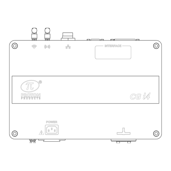
Page 10: Dimensional Drawings (Cg- I 4 Control Box )
(CG- IMENSIONAL DRAWINGS ONTROL CG-i4 Serie Capacitance Gauges Instruction Manual (Issue 1c) Page 10... -
Page 11: Nnotated Rawings
NNOTATED RAWINGS VERVIEW Description CG-i4 insulation capacitance gauge head. Push-fit water inlet / outlet (for production lines without fully submerged water cooling). Removable ceramic cable guide end cap. CG-i4 gauge head to Control Box connection cable (1.5m fixed length). Control Box (signal processing and interface unit). ONTROL ONNECTOR ANEL... -
Page 12: Led Status Indicators
LED S TATUS NDICATORS Designation Description LED status Indication Continuous red Unit is powered on Power indicator LED Extinguished Unit is powered off Continuous green CANbus online CANbus indicator LED Extinguished No CANbus communications Continuous green Industrial bus online i-BUS Industrial bus indicator LED Extinguished No industrial bus communications... -
Page 13: Installation
The CG-I4 gauge head end cap ceramic cable seals should be regularly checked for dirt or debris and cleaned accordingly. End cap cable seals should be replaced if they exhibit wear or damage. Replacement CG-I4 gauge head end caps may be ordered from your Proton Products representative:... -
Page 14: Mechanical Installation
ECHANICAL NSTALLATION • The CG-I4 gauge head is designed to be mounted in the post-extrusion water cooling trough and requires its bore to be fully flooded with water for accurate capacitance measurement. • The CG-I4 gauge head should be mounted in the water cooling trough such that the interconnection cable connector is kept above the water surface. -
Page 15: Electrical Installation
All earth wires must be bonded to a reliable earth point. Communications interfaces Connect to the required communications interface (CANbus if using a Proton Products CDI4, RS-232 or i-BUS). For further information, refer to the chapters detailing the relevant communications interface. -
Page 16: Power Supply
Power supply Specification Minimum Typical Maximum Units AC Power supply voltage AC Power supply frequency AC Power consumption Powering on the unit The unit is not fitted with a power switch; as soon as DC power is applied it will power up and perform self-tests before commencing measurements. -
Page 17: Operation
PERATION Set Zero offset Prior to setting the Zero offset, ensure that: • No wire is running through the CG-I4 gauge head. • The CG-I4 gauge head bore is completely flooded with water. In the absence of any wire in the CG-I4 gauge head, set the “Zero offset” parameter on Measurement page 1 via CDI4 so that the “Measured capacitance value”... -
Page 18: Configuration Via Cdi4
CDI4 ONFIGURATION VIA Power on screen When the gauge is powered on, the Proton screen will be displayed momentarily. Touch screen calibration The CDI4 touch screen can be calibrated using the following procedure. 1. Press the “Click to calibrate touch screen” message during gauge power on to access the screen calibration function. -
Page 19: Home
Home page 1 - Gauge status - Measured capacitance - Capacitance error (measured capacitance – preset capacitance) - Graphic display of variation from preset value (green = within tolerance levels; red= tolerance levels exceeded) Press the button to access the function menu page. button to advance to “Home Page 2”. -
Page 20: Function Menus
Function menus Press the button on the home page to access this page. Press the Home icon to return to the home page; or press the other icons to access the respective configuration pages. Preset Press the Presets icon on the home page to access the Presets page 1. -
Page 21: Measurement
EASUREMENT Press the Measurement icon on the Menu page to access the measurement page 1. - Select the measurement unit from options: Metric; Imperial. - Set the time window over which capacitance measurements are averaged. - Set the compensation coefficient to compensate the measured capacitance value. -
Page 22: Simulation Mode
- Switch ON or OFF the simulation mode. - Set a simulation capacitance value. - Select the software language from options: English; Chinese. - Input “63000” for the password then click “OK” on the pop- up page to restore all parameters to factory defaults. Press the button to return to the home page. -
Page 23: Communications
- Set the Modbus ID of the gauge head. - Select RS232 baud rate from options: 4800; 9600; 19200; 38400; 115200. - Select RS232 mode from options: PROTON; Modbus. - Select RS422 baud rate from options: 4800; 9600; 19200; 38400;115200. - Page 24 - Enable or disable the DHCP function. - Set the IP address of the gauge head then click the “OK” button to confirm. - Set the Subnet Mask of the network then click the “OK” button to confirm. - Set the Gateway IP address of the network then click the “OK”...
- Page 25 - Enable or disable the DHCP function. - Set the IP address of the gauge head then click the “OK” button to confirm. - Set the Subnet Mask of the WiFi network then click the “OK” button to confirm. - Set the Gateway IP address of the WiFi network then click the “OK”...
- Page 26 - Current iBUS type display - Select the industrial communication bus type. Note that if the iBUS type is changed, the gauge must be reboot to take effect. - Set the device ID of the gauge. - Select the DeviceNet baud rate from options: 125K; 250K; 500K.
-
Page 27: Interface
INTERFACE Press the Interface icon on the function menu page to access the Interface page 1. - Select the analogue output 1 function. - Select the analogue output 2 function. - Select the analogue output 3 function. - Set the analogue output 1 full scale. - Set the analogue output 2 full scale. - Page 28 - Select the condition under which this relay contact will close (short-circuit). - Same as above. - Same as above. - Same as above. - Set the relay contact closure time duration (this setting applies to all four relays). Note that “Closure time” only works on the tolerance functions: Over upper limit and Under lower limit.
- Page 29 - Select the logic input 1 function. - Select the logic input 1 polarity. - Select the logic input 2 function. - Select the logic input 2 polarity. Press the button to return to the home page. Press the button to access the function menu page. Press the button to advance to the next page.
-
Page 30: Gauge Information
- Set the PID controller output voltage range (0 to 50%). - Set the wire path distance between the gauge and the PID controlled equipment (extruder or capstan). - Set the response time of the PID controlled equipment (extruder or capstan; typically 1s). - Set the minimum line speed for PID controller operation. - Page 31 - Last gauge calibration date. - Number of days since last gauge calibration. - 0=ok (no need for calibration); 1=alarm (more than 365 days since last calibration and needs to be recalibrated) - Gauge total run time. - Gauge power up time. - Highest value of the gauge case temperature.
-
Page 32: Store
Store Press the Store icon on the function menu page to access this page. - Enter the parameter group (1 to 50). - Click the “Recall” button to recall the stored input parameter values in the group. - Click the “Save” button to save changes to the current active group after modifying the input parameter values. -
Page 33: Fft
Press the FFT icon on the function menu page to access this page. - FFT graph. - Set the FFT sampling cable length. - Set the velocity of propagation (in percentage) at which an electrical signal can propagate through the cable in comparison to the speed of light. - Page 34 FFT graph X axis: capacitance variation frequency (Hz); Y axis: the capacitance variation amplitude value (pF/m) SRL graph X axis: The frequency of the test signal (MHz); Y axis: SRL value (dB). CG-i4 Serie Capacitance Gauges Instruction Manual (Issue 1c) Page 34...
-
Page 35: Access Levels
ACCESS LEVELS Press the Access levels icon on the function menu page and input the password “18018” to enter the access levels pages. The “Access levels” page is a password protected page which restricts the setting of parameters. The Home pages and the function menu pages can be locked or unlocked by selecting “Locked” or “Unlocked”. -
Page 36: Standard Communications Interfaces
This CAN-bus interface is fitted as standard. It operates independently of the other communications interfaces and may be accessed at the same time as them. The CAN-bus interface uses a proprietary Proton Products protocol. It is exclusively used to communicate between the unit and other Proton Products modules. The unit automatically detects connection to other modules and configures the bus appropriately;... -
Page 37: Ethernet Communications
RS422_Y CTS1 RTS1 RS422_Z Ensure that the cable shield is connected to this Shield via the plug shield connection. The above table also shows the configuration of a cable for connection to a personal computer (PC) type DB9 serial port. The maximum baud rate depends on the cable capacitance and length. -
Page 38: I-Bus Communications
I-BUS communications This communications interface operates independently of the other communications interfaces and may be used at the same time as them. IBUS interface The IBUS interface may be accessed through the “I-BUS” connector. Connector type: DB9 female (socket) PROFIBUS ETHERNET / IP / PROFINET Comments PROFI B... -
Page 39: Standard Electrical Interfaces
TANDARD LECTRICAL NTERFACES Logic inputs Two logic inputs are fitted as standard and may be accessed through the “INTERFACE” connector. Connector type: DB25 female (socket) Designation Description Notes LIN2 Logic input 2 DGND Digital ground Ground reference for LIN1 and LIN2. LIN1 Logic input 1 Ensure that the cable shield is connected to this via the plug... - Page 40 Pull down Pull up +15V +15V 5.1kΩ 5.1kΩ 820Ω From PLC Active High Logic Output 820Ω DGND DGND CG-i4 Serie Capacitance Gauges Instruction Manual (Issue 1c) Page 40...
-
Page 41: Relay Outputs
On resistance (at a current of 10mA) Speed pulse inputs The speed pulse input may be connected to a line speed gauge (such as a Proton Products SL or SLR series non-contact laser speed and length gauge). Measured line speed input is required for: •... -
Page 42: Speed Pulse Input Connection
Speed pulse input connection The speed pulse input is fitted as standard and may be accessed through the “INTERFACE” connector. Connector type: DB25 female (socket) Designation Description Notes DGND Digital ground Ground reference for SPD1 and SPD2. SPD2 Speed pulse input 2 For low voltage speed pulses (e.g. -
Page 43: Optional Electrical Interfaces
PTIONAL ELECTRICAL INTERFACES Speed analogue input The analogue input may be connected to a 0 to +10V signal from a line speed gauge. Measured line speed input is required for: • PI feedback controller operation. • Statistical Process Control (SPC) operation. Analogue input connection If installed, the analogue input may be accessed through the “INTERFACE”... -
Page 44: Analogue Outputs
Analogue outputs Analogue outputs are an optional extra that must be ordered for installation during manufacture; they cannot be retrofitted to the gauge. The analogue outputs may be configured to output capacitance or error measurements as an analogue output voltage. Analogue outputs connection Three analogue outputs may be accessed through the “INTERFACE”... -
Page 45: Interface Connector Pin Outs
NTERFACE CONNECTOR PIN OUTS Connector type: DB25 female (socket) Designation Functional group Description Notes PI feedback controller PI feedback controller ground Isolated ground POUT PI feedback controller PI feedback controller output ±10V isolated output ±10V full scale isolated AOUT1 Analogue outputs Analogue output 1 output ±10V full scale isolated... -
Page 46: Roton Tandard Arameter Ccess Rotocol
ROTOCOL This protocol provides access to individual parameters or blocks of parameters and is typically used in a production environment where the Proton Products instrument is connected to a computer, Modbus connected PLC or similar device. The parameters consist of 16-bit words (DW) and are divided into input and output groups: •... - Page 47 For Modbus protocol communications via the RS-232 serial port, the RS-232 data format is: Number of data bits Parity Number of stop bits Flow control Default baud rate None None 115200 bit / s CG-i4 Serie Capacitance Gauges Instruction Manual (Issue 1c) Page 47...
-
Page 48: Input Parameters
NPUT PARAMETERS Comments Unit Range/Remark Default value Measurement Reserved Unit 0=Metric;1=Imperial Preset capacitance 1=0.1pF/m / 1000 value 1=0.01pF/ft Preset capacitance 1=0.1pF/m / value upper limit 1=0.01pF/ft Preset capacitance 1=0.1pF/m / value lower limit 1=0.01pF/ft Capacitance zero 1=0.1pF/m / offset 1=0.01pF/ft Average time 1=1ms 1~5000... - Page 49 Comments Unit Range/Remark Default value 1=Over upper limit; 2=Under lower limit; Relay 4 function DW102 Relay closure time 1=1ms 1~5000 DW103 Relay alarm filter time 1=1ms 1~5000 Logic input LIN1 function LIN2 function 0=Reset DW104 Reserved LIN1 polarity 0=Active low; LIN2 polarity 1=Active high Reserved...
- Page 50 Comments Unit Range/Remark Default value DW113 Analogue O/P Analogue O/P 1 DW114 0=Capacitance; 1=Capacitance Error; Analogue O/P2 Analogue O/P 3 0=Capacitance; DW115 1=Capacitance Error; Analogue O/P4 (reserved) Full scale for 1=0.1pF/m / DW116 0~65535 10000 analogue O/P 1 1=0.01pF/ft Full scale for 1=0.1pF/m / DW117 0~65535...
- Page 51 Interface output DW127 0=Averaged;1=Instant response DW128 DW129 Communication DW200 Modbus ID 0~255 0=4800;1=9600;2=19200 DW201 RS232 baud rate ;3=38400;4=115200 DW202 RS232 protocol 0=Modbus;1=Proton; 0=4800;1=9600;2=19200 RS422/RS485 baud ;3=38400;4=115200;5=2 DW203 rate 30400;6=460800;7=9216 RS422/RS485 DW204 0=Modbus;1=Proton protocol DW205 DW206 DW207 CANBUS address 0~255 0=250;1=500;2=1000;oth...
- Page 52 Comments Unit Range/Remark Default value DW224 0=NONE;1=PROFIBUS;2 DW225 iBus type selection =PROFINET;3=Ethernet/I iBus little endian/big 0=Big Endian;1=Little DW226 endian Endian; DW227 Profibus ID 0~125 DW228 DeviceNet address 0~63 DW229 DeviceNet baud rate 0=125K;1=250K;2=500K DW230 DW231 iBus DHCP 0=Disabled;1=Enabled DW232 C0A80170(192. iBus IP address xx.xx.xx.xx 168.1.112)
-
Page 53: Output Parameters
Comments Unit Range/Remark Default value DW320 DW321 30 bytes DW322 OPC server DW355 0=No, 1=Yes anonymous OPC TCP port DW356 0~65535 4840 number DW357 DW358 DW359 DW360 16 bytes OPC user name admin DW361 DW362 DW363 DW364 DW365 DW366 DW367 DW368 16 bytes OPC user password... - Page 54 Comments Units Range/Remark No Cable 0=OK;1=No Cable Overload 0=OK;1=Overload Parameter changed Over upper limit 0=OK;1=Over limit Under lower limit 0=OK;1=Under limit Capacitance value 1=0.1pF/m / 1=0.01pF/ft Capacitance error DW10 DW11 Line speed 1=0.1m/min{1=0.1ft/min} -32768~32767 DW12 Length 1=0.001m{1=0.001ft} DW13 DW14 Control status 0=OFF;1=ON;2=Reset;3=Ready DW15 Control output...
- Page 55 Comments Units Range/Remark DW32 FFT peak 1=0.01pF/m / 1=0.01pF/ft DW33 FFT peak length 1=1cm(1=1inch) 0~65535cm DW34 FFT peak freq 1=0.1Hz DW35 Communication 0=NONE;1=PROFIBUS;2=PROFIN DW200 iBus Type ET;3=Ethernet/IP; DW201 Not used DW202 IP address for ETH xx.xx.xx.xx DW203 DW204 Subnet mask for ETH xx.xx.xx.xx DW205 DW206...
-
Page 56: Ontact Details For Enquiries Sales And Service
Proton Products is not responsible for consequential or incidental damage related to the provision or use of the information contained in this manual. • The information contained in this manual is the property of Proton Products and may not be circulated or distributed to third parties. •...
Need help?
Do you have a question about the InteliSENS CG-i4 Series and is the answer not in the manual?
Questions and answers