
Related Manuals for Daikin ERA250AMYFB


Summary of Contents for Daikin ERA250AMYFB
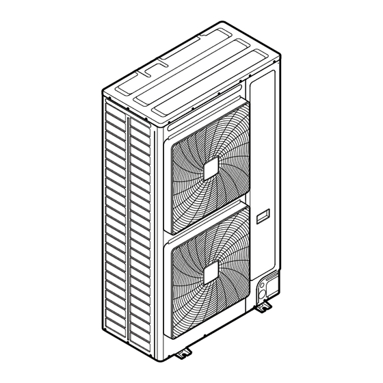
- Page 1 Installer and user reference guide Inverter outdoor unit for AHU option kit and air curtains ERA200AMYFB ERA250AMYFB ERA300AMYFB...
-
Page 2: Table Of Contents
Table of contents Table of contents 1 About this document Meaning of warnings and symbols ..........................2 General safety precautions For the installer ................................2.1.1 General................................2.1.2 Installation site............................... 2.1.3 Refrigerant — in case of R410A or R32......................2.1.4 Electrical................................. 3 Specific installer safety instructions Instructions for equipment using R32 refrigerant...................... - Page 3 Table of contents For the installer 13 About the box 13.1 To unpack the outdoor unit ............................13.2 To handle the outdoor unit............................13.3 To remove the accessories from the outdoor unit......................13.4 To remove the transportation stay..........................14 About the units and options 14.1 Identification label: Outdoor unit ..........................
- Page 4 Table of contents 18.7 To fix the fluorinated greenhouse gases label....................... 18.8 To check refrigerant piping joints for leaks after charging refrigerant................. 19 Electrical installation 19.1 About connecting the electrical wiring.......................... 19.1.1 Precautions when connecting the electrical wiring..................19.1.2 About the electrical wiring ..........................19.1.3 Guidelines for making knockout holes ......................
-
Page 5: About This Document
Preparation of the installation, reference data,… Detailed step-by-step instructions and background information for basic and advanced usage Format: Digital files on https://www.daikin.eu. Use the search function find your model. The latest revision of the supplied documentation is published on the regional Daikin website and is available via your dealer. - Page 6 About this document WARNING: FLAMMABLE MATERIAL CAUTION Indicates a situation that could result in minor or moderate injury. NOTICE Indicates a situation that could result in equipment or property damage. INFORMATION Indicates useful tips or additional information. Symbols used on the unit: Symbol Explanation Before installation, read the installation and operation...
-
Page 7: General Safety Precautions
WARNING Improper installation or attachment of equipment or accessories could result in electrical shock, short-circuit, leaks, fire or other damage to the equipment. ONLY use accessories, optional equipment and spare parts made or approved by Daikin unless otherwise specified. WARNING Make sure installation, testing and applied materials comply with applicable legislation (on top of the instructions described in the Daikin documentation). -
Page 8: Installation Site
General safety precautions CAUTION ▪ Do NOT place any objects or equipment on top of the unit. ▪ Do NOT sit, climb or stand on the unit. NOTICE Works executed on the outdoor unit are best done under dry weather conditions to avoid water ingress. - Page 9 General safety precautions WARNING During tests, NEVER pressurise the product with a pressure higher than the maximum allowable pressure (as indicated on the nameplate of the unit). WARNING Take sufficient precautions in case of refrigerant leakage. If refrigerant gas leaks, ventilate the area immediately.
-
Page 10: Electrical
General safety precautions Then A siphon tube is NOT present Charge with the cylinder upside down. ▪ Open refrigerant cylinders slowly. ▪ Charge the refrigerant in liquid form. Adding it in gas form may prevent normal operation. CAUTION When the refrigerant charging procedure is done or when pausing, close the valve of the refrigerant tank immediately. - Page 11 General safety precautions WARNING ▪ After finishing the electrical work, confirm that each electrical component and terminal inside the switch box is connected securely. ▪ Make sure all covers are closed before starting up the unit. CAUTION ▪ When connecting the power supply: connect the earth cable first, before making the current-carrying connections.
-
Page 12: Specific Installer Safety Instructions
Specific installer safety instructions 3 Specific installer safety instructions Always observe the following safety instructions and regulations. Installation site (see "16.1 Preparing the installation site" [ 65]) WARNING Follow the service space dimensions in this manual to install the unit correctly. See "26.1 Service space: Outdoor unit" [ 141]. - Page 13 Specific installer safety instructions CAUTION ▪ Do NOT use mineral oil on flared part. ▪ Do NOT reuse piping from previous installations. ▪ NEVER install a drier to this unit to guarantee its lifetime. The drying material may dissolve and damage the system. CAUTION Install the refrigerant piping or components in a position where they are unlikely to be exposed to any substance which may corrode components containing refrigerant,...
- Page 14 Specific installer safety instructions "18 Charging refrigerant" [ 89]) Charging refrigerant (see WARNING ▪ The refrigerant inside the unit is mildly flammable, but normally does NOT leak. If the refrigerant leaks in the room and comes in contact with fire from a burner, a heater, or a cooker, this may result in fire, or the formation of a harmful gas.
- Page 15 Specific installer safety instructions WARNING ▪ All wiring MUST be performed by an authorised electrician and MUST comply with the national wiring regulation. ▪ Make electrical connections to the fixed wiring. ▪ All components procured on-site and all electrical construction MUST comply with the applicable legislation.
-
Page 16: Instructions For Equipment Using R32 Refrigerant
53]. WARNING Make sure installation, servicing, maintenance and repair comply with instructions from Daikin and with applicable legislation (for example national gas regulation) and are executed ONLY by authorised persons. ERA200~300AMYFB Installer and user reference guide Inverter outdoor unit for AHU option kit and air curtains... - Page 17 Specific installer safety instructions WARNING ▪ Take precautions to avoid excessive vibration or pulsation to refrigeration piping. ▪ Protect the protection devices, piping and fittings as much as possible against adverse environmental effects. ▪ ALWAYS support the piping at distances of 1 m and 2 m from the indoor unit. ▪...
-
Page 18: For The User
For the user ERA200~300AMYFB Installer and user reference guide Inverter outdoor unit for AHU option kit and air curtains 4P780154-1 – 2024.09... -
Page 19: User Safety Instructions
User safety instructions 4 User safety instructions Always observe the following safety instructions and regulations. In this chapter General....................................Instructions for safe operation............................... 4.1 General WARNING If you are NOT sure how to operate the unit, contact your installer. WARNING This appliance can be used by children aged from 8 years and above and persons with reduced physical, sensory or mental capabilities or lack of experience and knowledge if... -
Page 20: Instructions For Safe Operation
4.2 Instructions for safe operation WARNING Make sure installation, servicing, maintenance, repair and applied materials follow the instructions from Daikin (including all documents listed in “Documentation set”) and, in addition, comply with applicable legislation and are performed by qualified persons only. In Europe and areas where IEC standards apply, EN/IEC 60335-2-40 is the applicable standard. - Page 21 User safety instructions CAUTION ▪ NEVER touch the internal parts of the controller. ▪ Do NOT remove the front panel. Some parts inside are dangerous to touch and appliance problems may happen. For checking and adjusting the internal parts, contact your dealer. CAUTION Do NOT operate the system when using a room fumigation-type insecticide.
- Page 22 User safety instructions CAUTION Do NOT insert fingers, rods or other objects into the air inlet or outlet. Do NOT remove the fan guard. When the fan is rotating at high speed, it will cause injury. CAUTION: Pay attention to the fan! It is dangerous to inspect the unit while the fan is running.
- Page 23 User safety instructions WARNING ▪ Do NOT pierce or burn refrigerant cycle parts. ▪ Do NOT use cleaning materials or means to accelerate the defrosting process other than those recommended by the manufacturer. ▪ Be aware that the refrigerant inside the system is odourless.
- Page 24 User safety instructions CAUTION Do NOT touch the heat exchanger fins. These fins are sharp and could result in cutting injuries. ERA200~300AMYFB Installer and user reference guide Inverter outdoor unit for AHU option kit and air curtains 4P780154-1 – 2024.09...
-
Page 25: About The System
About the system 5 About the system The ERA uses R32 refrigerant which is rated as A2L and is mildly flammable. For compliance with the requirements for enhanced tightness refrigerating systems and IEC60335-2-40 the installer must take extra measures. For more information, "3.1 Instructions for equipment using R32 refrigerant" [ 16]. -
Page 26: System Layout
About the system 5.1 System layout INFORMATION The following figure is an example and may NOT completely match your system layout. AHU connection O / U A H U E K E X V A B R C E K E A C o n t r . -
Page 27: User Interface
User interface 6 User interface CAUTION ▪ NEVER touch the internal parts of the controller. ▪ Do NOT remove the front panel. Some parts inside are dangerous to touch and appliance problems may happen. For checking and adjusting the internal parts, contact your dealer. -
Page 28: Operation
Operation 7 Operation In this chapter Before operation ..................................Operation range..................................Operating the system ................................7.3.1 About operating the system ..........................7.3.2 About cooling, heating, fan only, and automatic operation ................. 7.3.3 About the heating operation ..........................7.3.4 To operate the system (WITHOUT cool/heat changeover remote control switch) ..........7.3.5 To operate the system (WITH cool/heat changeover remote control switch) ............ -
Page 29: Operating The System
Operation To avoid condensation and water dripping out of the unit. If the temperature or the humidity is beyond these conditions, safety devices may be put in action and the air conditioner may not operate. Above operation range is only valid in case direct expansion indoor units are connected to the ERA system. -
Page 30: To Operate The System (Without Cool/Heat Changeover Remote Control Switch)
Operation INFORMATION ▪ The heating capacity drops when the outside temperature falls. If this happens, use another heating device together with the unit. (When using together with appliances that produce open fire, ventilate the room constantly). Do not place appliances that produce open fire in places exposed to the air flow from the unit or under the unit. - Page 31 Operation 2 Press the ON/OFF button on the user interface. Result: The operation lamp lights up and the system starts operating. To stop 3 Press the ON/OFF button on the user interface once again. Result: The operation lamp goes out and the system stops operating. NOTICE Do not turn off power immediately after the unit stops, but wait for at least 5 minutes.
-
Page 32: Energy Saving And Optimum Operation
Energy saving and optimum operation 8 Energy saving and optimum operation Observe the following precautions to ensure the system operates properly. ▪ Adjust the air outlet properly and avoid direct air flow to room inhabitants. ▪ Adjust the room temperature properly for a comfortable environment. Avoid excessive heating or cooling. -
Page 33: Available Main Operation Methods
Energy saving and optimum operation 8.1 Available main operation methods Basic The refrigerant temperature is fixed independent from the situation. Automatic The refrigerant temperature is set depending on the outdoor ambient conditions. As such adjusting the refrigerant temperature to match the required load (which is also related to the outdoor ambient conditions). -
Page 34: Maintenance And Service
Maintenance and service 9 Maintenance and service In this chapter Precautions for maintenance and service..........................About the refrigerant ................................After-sales service................................... 9.3.1 Recommended maintenance and inspection......................9.3.2 Recommended maintenance and inspection cycles..................... 9.3.3 Shortened maintenance and replacement cycles....................9.1 Precautions for maintenance and service CAUTION "4 User safety instructions" [... -
Page 35: After-Sales Service
Maintenance and service 9.3 After-sales service 9.3.1 Recommended maintenance and inspection Since dust collects when using the unit for several years, performance of the unit will deteriorate to some extent. As taking apart and cleaning interiors of units requires technical expertise and in order to ensure the best possible maintenance of your units, we recommend to enter into a maintenance and inspection contract on top of normal maintenance activities. -
Page 36: Shortened Maintenance And Replacement Cycles
Maintenance and service NOTICE ▪ The table indicates main components. Refer to your maintenance and inspection contract for more details. ▪ The table indicates recommended intervals of maintenance cycles. However, in order to keep the unit operational as long as possible, maintenance work may be required sooner. -
Page 37: Troubleshooting
Troubleshooting 10 Troubleshooting If one of the following malfunctions occurs, take the measures shown below and contact your dealer. WARNING Stop operation and shut OFF the power if anything unusual occurs (burning smells etc.). Leaving the unit running under such circumstances may cause breakage, electrical shock or fire. - Page 38 Troubleshooting Malfunction Measure The system operates but ▪ Check if air inlet or outlet of outdoor or indoor cooling or heating is unit is not blocked by obstacles. Remove any insufficient. obstacles and make sure the air can flow freely. ▪...
-
Page 39: Error Codes: Overview
Troubleshooting 10.1 Error codes: Overview In case a malfunction code appears on the indoor unit user interface display, contact your installer and inform the malfunction code, the unit type, and serial number (you can find this information on the nameplate of the unit). For your reference, a list with malfunction codes is provided. -
Page 40: Symptoms That Are Not System Malfunctions
Troubleshooting Main code Contents Suction temperature sensor malfunction (outdoor) De-icing temperature sensor malfunction (outdoor) or heat exchanger gas temperature sensor malfunction (outdoor) Liquid temperature sensor (after subcool HE) malfunction (outdoor) Liquid temperature sensor (coil) malfunction (outdoor) Gas temperature sensor (after subcool HE) malfunction (outdoor) High pressure sensor malfunction (S1NPH) Low pressure sensor malfunction (S1NPL) INV PCB abnormal... -
Page 41: Symptom: The System Does Not Operate
Troubleshooting 10.2.1 Symptom: The system does not operate ▪ The air conditioner does not start immediately after the ON/OFF button on the user interface is pressed. If the operation lamp lights, the system is in normal condition. To prevent overloading of the compressor motor, the air conditioner starts 5 minutes after it is turned ON again in case it was turned OFF just before. -
Page 42: Symptom: Noise Of Air Conditioners (Outdoor Unit)
Troubleshooting ▪ A hissing sound which is heard at the start or immediately after stopping operation or defrost operation. This is the noise of refrigerant caused by flow stop or flow change. 10.2.8 Symptom: Noise of air conditioners (Outdoor unit) When the tone of operating noise changes. -
Page 43: Relocation
Relocation 11 Relocation Contact your dealer to remove and reinstall the entire unit. Moving units requires technical expertise. ERA200~300AMYFB Installer and user reference guide Inverter outdoor unit for AHU option kit and air curtains 4P780154-1 – 2024.09... -
Page 44: Disposal
Disposal 12 Disposal This unit uses hydrofluorocarbon. Contact your dealer when discarding this unit. It is required by law to collect, transport and discard the refrigerant in accordance with the "hydrofluorocarbon collection and destruction" regulations. NOTICE Do NOT try to dismantle the system yourself: dismantling of the system, treatment of the refrigerant, oil and other parts MUST comply with applicable legislation. -
Page 45: For The Installer
For the installer ERA200~300AMYFB Installer and user reference guide Inverter outdoor unit for AHU option kit and air curtains 4P780154-1 – 2024.09... -
Page 46: About The Box
About the box 13 About the box Keep the following in mind: ▪ At delivery, the unit MUST be checked for damage and completeness. Any damage or missing parts MUST be reported immediately to the claims agent of the carrier. ▪... -
Page 47: To Handle The Outdoor Unit
About the box ERA250+300 4× 13.2 To handle the outdoor unit CAUTION To avoid injury, do NOT touch the air inlet or aluminium fins of the unit. Forklift. If the unit remains on its pallet, Crane. For ERA250+300 models, you you can also use a forklift. -
Page 48: To Remove The Accessories From The Outdoor Unit
About the box ERA200 ±134 ERA250+300 ±163 13.3 To remove the accessories from the outdoor unit 1 Remove the service cover. See "16.2.2 To open the outdoor unit" [ 70]. 2 Remove the accessories. ERA200 ERA250+300 1× 2× 1× 1× 1× 1× 1×... - Page 49 About the box The transportation stay for protecting the unit during transport must be removed. Proceed as shown in the figure and procedure below. 1 Remove the bolt (a) and washers. 2 Remove the transportation stay (b) as shown in the figure below. a Bolt b Transportation stay ERA200~300AMYFB...
-
Page 50: About The Units And Options
About the units and options 14 About the units and options In this chapter 14.1 Identification label: Outdoor unit............................14.2 About the outdoor unit ................................14.3 System layout..................................14.4 Combining units and options ..............................14.4.1 About combining units and options ........................14.4.2 Possible options for the outdoor unit........................ -
Page 51: System Layout
About the units and options 14.3 System layout WARNING The installation MUST comply with the requirements that apply to this R32 equipment. For more information, see "15 Special requirements for R32 units" [ 53]. INFORMATION The following figure is an example and may NOT completely match your system layout. -
Page 52: Combining Units And Options
About the units and options f Centralised controller (optional) INFORMATION An air curtain is a heating-only product designed primarily for providing air separation. Therefore, it cannot be considered a comfort product. 14.4 Combining units and options INFORMATION Certain options may NOT be available in your country. 14.4.1 About combining units and options NOTICE Only one indoor unit pair application is allowed for the ERA outdoor unit, this means:... -
Page 53: Special Requirements For R32 Units
Special requirements for R32 units 15 Special requirements for R32 units In this chapter 15.1 Requirements for compatible air curtains ..........................15.1.1 Installation space requirements ..........................15.1.2 System layout requirements..........................15.1.3 To determine the required safety measures......................15.1.4 Safety measures ..............................15.2 Requirements for air handling units............................ - Page 54 Special requirements for R32 units For more information about the SVS output, see "19.3 To connect the external outputs" [ 104]. Indoor unit installation For installation of the compatible air curtain, refer to the installation and operation manual delivered with the air curtain. For compatibility of air curtain refer to the latest version of the technical data book of this outdoor unit.
-
Page 55: To Determine The Required Safety Measures
Special requirements for R32 units 15.1.3 To determine the required safety measures Step 1 – Determine the total amount of refrigerant in the system. Use the values on the unit nameplate to determine the total amount of refrigerant in the system. Contains fluorinated greenhouse gases GWP: xxx GWP ×... - Page 56 Special requirements for R32 units [m²] [m²] m [kg] Lowest underground floor All other floors m [kg] Lowest underground floor All other floors No safety measure Alarm OR No safety measure No safety measure Alarm OR No safety measure Natural ventilation Natural ventilation 15.4 10.3...
- Page 57 Special requirements for R32 units NOTICE A compatible air curtain cannot be installed lower than 1.8 m from the lowest point of the floor. Example The total amount of refrigerant in the ERA system is 10 kg. The air curtain is installed in spaces that do NOT belong to the lowest underground floor of the building.
-
Page 58: Overview: Flowchart
Special requirements for R32 units Overview: flowchart Procedure to check required countermeasure for indoor unit Determine total amount of See Step 1 in above text refrigerant in the system. Total charge amount [kg] Determine the area of the room where an See Step 2 in above text air curtain is installed/serving. -
Page 59: Safety Measures
Special requirements for R32 units 15.1.4 Safety measures No safety measure When the room area is sufficiently large, no safety measures are required. This also includes an indoor unit installed in the lowest underground floor. Therefore the R32 safety system in the indoor unit in a sufficiently large room can be deactivated (active by default) by changing the setting in the user interface as shown below: Field settings... - Page 60 Special requirements for R32 units Note: The remote controllers with built-in alarm will generate a visible and audible warning. E.g. the BRC1H52/82* remote controllers can generate an alarm of 65 dB (sound pressure, measured at 1 m distance of the alarm). Sound data is available in the technical data sheet of the remote controller.
- Page 61 Special requirements for R32 units 2 Indoor units without remote controller are not allowed. 3 In case of two R32 safety system compatible remote controllers, at least one remote controller should be in the room of the indoor. 4 In particular situations it is mandatory to install a remote controller at a supervised location.
- Page 62 Special requirements for R32 units [m²] [kg] 10.1 13.5 16.8 20.2 23.6 27.0 30.3 33.7 37.1 40.5 43.9 47.2 50.6 54.0 57.4 60.7 64.1 67.5 70.9 74.2 77.6 79.6 79.8 79.8 m [kg] 79.8 m Total refrigerant charge limit in the system [kg] Area of the room with natural ventilation [m²] A Area of the room where an air curtain is installed/serving [m²] Note: Round down the derived values.
- Page 63 Special requirements for R32 units ▪ The area of any openings above 300 mm from the floor does not count when determining A nvmin ▪ At least 50% of A is less than 200 mm above the floor nvmin ▪ The bottom of the lower opening is ≤100 mm from the floor ▪...
-
Page 64: Requirements For Air Handling Units
Special requirements for R32 units Overview: flowchart Alarm Natural ventilation No safety measure Do NOT use 'Alarm' as the ONLY safety measure in case the air Make field settings in the curtain is installed in an occupied space where people are Determine total room area (= total area of the space with natural indoor unit accordingly. -
Page 65: Unit Installation
Unit installation 16 Unit installation WARNING The installation MUST comply with the requirements that apply to this R32 equipment. For more information, see "15 Special requirements for R32 units" [ 53]. In this chapter 16.1 Preparing the installation site ..............................16.1.1 Installation site requirements of the outdoor unit ....................16.1.2 Additional installation site requirements of the outdoor unit in cold climates ........... - Page 66 Unit installation INFORMATION Equipment meets the requirement for commercial and light-industrial location when professionally installed and maintained. ▪ The outdoor unit is designed for outdoor installation only, and for the following ambient temperatures: Heating –20~21°C DB –20~15.5°C WB Cooling –5~52°C DB Note: For indoor installation of the outdoor unit, check the applicable legislation. NOTICE The equipment described in this manual may cause electronic noise generated from radio-frequency energy.
- Page 67 Unit installation ▪ Heat exchanger fins are sharp and injury is possible. Choose an installation location where there is no risk for injury (especially in areas where children play). Do NOT install the unit in the following places: ▪ In potentially explosive atmospheres. ▪...
- Page 68 Unit installation a Sea wind b Building c Outdoor unit d Windbreaker Strong winds (≥18 km/h) blowing against the outdoor unit’s air outlet causes short circuit (suction of discharge air). This may result in: ▪ deterioration of the operational capacity; ▪ frequent frost acceleration in heating operation;...
-
Page 69: Additional Installation Site Requirements Of The Outdoor Unit In Cold Climates
Unit installation a Make sure there is enough installation space Set the air outlet side at a right angle to the direction of the wind. a Prevailing wind direction b Air outlet 16.1.2 Additional installation site requirements of the outdoor unit in cold climates Protect the outdoor unit against direct snowfall and take care that the outdoor unit is NEVER snowed up. -
Page 70: Opening And Closing The Unit
If the unit is selected to operate at ambient temperatures lower than –5°C for 5 days or longer, with relative humidity levels exceeding 95%, we recommend to apply a Daikin range specifically designed for such application and/or to contact your dealer for further advice. -
Page 71: To Close The Outdoor Unit
Unit installation 2× 3× 16.2.3 To close the outdoor unit NOTICE When closing the outdoor unit cover, make sure that the tightening torque does NOT exceed 4.1 N•m. ERA200 ERA250+300 2× 3× 16.3 Mounting the outdoor unit 16.3.1 To provide the installation structure Check the strength and level of the installation ground so that the unit will not cause any operating vibration or noise. -
Page 72: To Install The Outdoor Unit
Unit installation INFORMATION The recommended height of the upper protruding part of the bolts is 20 mm. NOTICE Fix the outdoor unit to the foundation bolts using nuts with resin washers (a). If the coating on the fastening area is stripped off, the metal can rust easily. 16.3.2 To install the outdoor unit 4×... -
Page 73: To Prevent The Outdoor Unit From Falling Over
Unit installation NOTICE If drain holes of the outdoor unit are covered by a mounting base or by floor surface, raise the unit to provide a free space of more than 150 mm under the outdoor unit. Drain holes (dimensions in mm) Model Bottom view [mm] ERA200... -
Page 74: Piping Installation
Piping installation 17 Piping installation CAUTION "3 Specific installer safety instructions" [ 12] to make sure this installation complies with all safety regulations. In this chapter 17.1 Preparing refrigerant piping ..............................17.1.1 Refrigerant piping requirements ........................... 17.1.2 Refrigerant piping material............................ 17.1.3 Refrigerant piping insulation .......................... -
Page 75: Refrigerant Piping Insulation
Piping installation Piping temper grade and thickness Outer diameter (Ø) Temper grade Thickness (t) Ø 9.5 mm (3/8") Annealed (O) ≥0.80 mm 12.7 mm (1/2") 15.9 mm (5/8") Annealed (O) ≥0.99 mm 19.1 mm (3/4") Half hard (1/2H) ≥0.80 mm 22.2 mm (7/8") Depending on the applicable legislation and the maximum working pressure of the unit (see "PS High"... -
Page 76: Refrigerant Piping Length And Height Difference
Piping installation Outdoor unit capacity Piping outer diameter [mm] type Gas pipe Liquid pipe ERA200 19.1 ERA250 ERA300 22.2 12.7 17.1.6 Refrigerant piping length and height difference The piping length and height difference must comply with the following requirements: a Outdoor unit b Air handling unit (AHU) c EKEXVA-kit Term... -
Page 77: Precautions When Connecting The Refrigerant Piping
Piping installation ▪ Connecting the refrigerant piping to the outdoor unit ▪ Connecting the refrigerant piping to the indoor unit ▪ Insulating the refrigerant piping ▪ Keeping in mind the guidelines for: Pipe bending Flaring pipe ends Brazing Using the stop valves 17.2.2 Precautions when connecting the refrigerant piping INFORMATION Also read the precautions and requirements in the following chapters:... -
Page 78: Pipe Bending Guidelines
Piping installation 17.2.3 Pipe bending guidelines Use a pipe bender for bending. All pipe bends should be as gentle as possible (bending radius should be 30~40 mm or larger). 17.2.4 Using the stop valve and service port To handle the stop valve Take the following guidelines into account: ▪... -
Page 79: To Remove The Pinched Pipes
Piping installation 4 Install the dust cap. Result: The valve is now open. NOTICE Reinstall dust cap to prevent aging of O-ring and risk of leakage. To close the stop valve 1 Remove the stop valve cover. 2 Insert a hexagon wrench into the stop valve and turn the stop valve clockwise. 3 When the stop valve cannot be turned any further, stop turning. - Page 80 Piping installation 2 Connect the vacuuming/recovery unit through a manifold to the service port of all stop valves. a Service port b Stop valve 3 Recover gas and oil from the pinched piping by using a recovery unit. CAUTION Do NOT vent gases into the atmosphere. 4 When all gas and oil is recovered from the pinched piping, disconnect the charge hose and close the service ports.
-
Page 81: To Braze The Pipe End
Piping installation 17.2.6 To braze the pipe end NOTICE Precautions when connecting field piping. Add brazing material as shown in the figure. ≤Ø25.4 >Ø25.4 ▪ When brazing, blow through with nitrogen to prevent creation of large quantities of oxidised film on the inside of the piping. This film adversely affects valves and compressors in the refrigerating system and prevents proper operation. - Page 82 Piping installation INFORMATION ▪ Punch out the knockout (a) in the bottom plate or cover plate by tapping on the attachment points with a flat head screwdriver and a hammer. ▪ Optionally, cut out the slits (b) with a metal saw. NOTICE Precautions when making knockout holes: ▪...
- Page 83 Piping installation NOTICE When brazing: First braze the liquid side piping, then the gas side piping. Enter the electrode from the front of the unit and the welding torch from the right side to braze with the flames facing outside and avoid the compressor sound insulation and other piping.
-
Page 84: Checking The Refrigerant Piping
Piping installation The connections to the branch kits are the responsibility of the installer (field piping). 17.3 Checking the refrigerant piping 17.3.1 About checking the refrigerant piping Refrigerant piping works are Finish piping work finished? The indoor and outdoor unit are already powered ON? Use procedure: "Method 1: Before power ON... -
Page 85: Checking Refrigerant Piping: General Guidelines
Piping installation ▪ Performing vacuum drying to remove all moisture, air or nitrogen in the refrigerant piping. If there is a possibility of moisture being present in the refrigerant piping (for example, water may have entered the piping), first carry out the vacuum drying procedure below until all moisture has been removed. -
Page 86: To Perform A Leak Test
Piping installation Valve Status Valve A Open Valve B Open Valve C Open Liquid line stop valve Close Gas line stop valve Close NOTICE Indoor units should also be leak and vacuum tested. Keep any possible (field supplied) field piping valves open as well. 17.3.4 To perform a leak test The leak test must satisfy the specifications of EN378‑2. -
Page 87: To Insulate The Refrigerant Piping
Piping installation To remove all moisture from the system, proceed as follows: 1 Evacuate the system for at least 2 hours to a target vacuum of – 1 00.7 kPa (– 1 .007 bar)(5 Torr absolute). 2 Check that, with the vacuum pump turned off, the target vacuum is maintained for at least 1 hour. -
Page 88: To Check For Leaks After Charging Refrigerant
Piping installation f Liquid pipe insulation g Finishing tape 2 Install the service cover. Inside the outdoor unit To insulate the refrigerant piping, proceed as follows: a Insulation material b Caulking etc. 1 Insulate the liquid and gas piping. 2 Wind heat insulation around the curves, and then cover it with vinyl tape. 3 Make sure the field piping does not touch any compressor components. -
Page 89: Charging Refrigerant
Charging refrigerant 18 Charging refrigerant In this chapter 18.1 Precautions when charging refrigerant ..........................18.2 About charging refrigerant..............................18.3 About the refrigerant ................................18.4 To determine the additional refrigerant amount ........................18.5 To charge refrigerant................................18.6 Error codes when charging refrigerant ..........................18.7 To fix the fluorinated greenhouse gases label........................ -
Page 90: About Charging Refrigerant
Charging refrigerant NOTICE In case of maintenance and the system (outdoor unit+field piping+indoor unit(s)) does not contain any refrigerant any more (e.g., after refrigerant reclaim operation), the unit has to be charged with its original amount of refrigerant (refer to the nameplate on the unit) and the determined additional refrigerant amount. -
Page 91: To Determine The Additional Refrigerant Amount
Charging refrigerant Periodical inspections for refrigerant leaks may be required depending on the applicable legislation. Contact your installer for more information. NOTICE Applicable legislation on fluorinated greenhouse gases requires that the refrigerant charge of the unit is indicated both in weight and CO equivalent. -
Page 92: To Charge Refrigerant
Charging refrigerant 18.5 To charge refrigerant To speed up the refrigerant charging process, it is in case of larger systems recommended to first pre-charge a portion of refrigerant through the liquid line before proceeding with the manual charging. It can be skipped, but charging will take longer then. - Page 93 Charging refrigerant Then The determined additional refrigerant Disconnect the manifold from the amount is not reached yet liquid line. Continue with the "Charging refrigerant (in manual additional refrigerant charge mode)" instructions. Charging refrigerant (in manual additional refrigerant charge mode) The remaining additional refrigerant charge can be charged by operating the outdoor unit by means of the manual additional refrigerant charge mode.
-
Page 94: Error Codes When Charging Refrigerant
Charging refrigerant INFORMATION The manual refrigerant charge operation will automatically stop within 30 minutes. If charging is not completed after 30 minutes, perform the additional refrigerant charging operation again. 10 Open valve A. 11 Charge refrigerant until the remaining determined additional refrigerant amount is added, and then close valve A. -
Page 95: To Check Refrigerant Piping Joints For Leaks After Charging Refrigerant
Charging refrigerant NOTICE Applicable legislation on fluorinated greenhouse gases requires that the refrigerant charge of the unit is indicated both in weight and CO equivalent. Formula to calculate the quantity in CO equivalent tonnes: GWP value of the refrigerant × total refrigerant charge [in kg] / 1000 Use the GWP value mentioned on the refrigerant charge label. -
Page 96: Electrical Installation
Electrical installation 19 Electrical installation CAUTION "3 Specific installer safety instructions" [ 12] to make sure this installation complies with all safety regulations. In this chapter 19.1 About connecting the electrical wiring ..........................19.1.1 Precautions when connecting the electrical wiring ....................19.1.2 About the electrical wiring............................. - Page 97 Electrical installation INFORMATION Also read the precautions and requirements in the "2 General safety precautions" [ 7]. WARNING ▪ If the power supply has a missing or wrong N-phase, equipment might break down. ▪ Establish proper earthing. Do NOT earth the unit to a utility pipe, surge absorber, or telephone earth.
-
Page 98: About The Electrical Wiring
Electrical installation NOTICE ▪ The reversed phase protection detector of this product only functions when the product starts up. Consequently reversed phase detection is not performed during normal operation of the product. ▪ The reversed phase protection detector is designed to stop the product in the event of an abnormality when the product is started up. -
Page 99: Guidelines When Connecting The Electrical Wiring
Electrical installation a Knockout hole b Burr c Remove burrs d If there are any possibilities that small animals enter the system through the knockout holes, close the holes with packing materials (to be prepared on-site) 19.1.4 Guidelines when connecting the electrical wiring NOTICE We recommend using solid (single-core) wires. - Page 100 Electrical installation Use the following methods for installing wires: Wire type Installation method Single-core wire AA´ A´ Stranded conductor wire twisted to "solid-like" connection a Curled wire (single-core or twisted stranded conductor wire) b Screw c Flat washer Stranded conductor wire with round crimp-style terminal a Terminal...
-
Page 101: About Electrical Compliance
Electrical installation 19.1.5 About electrical compliance This equipment complies with: ▪ EN/IEC 61000‑3‑12 provided that the short-circuit power S is greater than or equal to the minimum S value at the interface point between the user's supply and the public system. EN/IEC 61000‑3‑12 = European/International Technical Standard setting the limits for harmonic currents produced by equipment connected to public low- voltage systems with input current >16 A and ≤75 A per phase. -
Page 102: To Connect The Electrical Wiring To The Outdoor Unit
Electrical installation NOTICE When using residual current operated circuit breakers, be sure to use a high-speed type 300 mA rated residual operating current. 19.2 To connect the electrical wiring to the outdoor unit CAUTION ▪ When connecting the power supply: connect the earth cable first, before making the current-carrying connections. - Page 103 Electrical installation a P-clamp for cable shield earthing Note: For ERA250+300 , the interconnection cable MUST pass through the ferrite core 3 times (3 passes, 2 turns). See illustration below: 3× a Interconnection cable b Ferrite core 4 Connect the power supply as follows: 3N~ 50 / 60 Hz 380-415 / 400 V L1 L2 L3...
-
Page 104: To Connect The External Outputs
Electrical installation 6 Route the cables through the frame according to the illustration below. Note: for ERA200, choose one of the two possibilities to route the cables through the frame. ERA250+300 ERA200 a Interconnection cable b Power supply cable 7 Remove the selected knockout holes by tapping on the attachment points with a flat head screwdriver and a hammer. -
Page 105: To Connect The Cool/Heat Selector Switch Option
Electrical installation Outdoor output connection requirements Wire size Only use harmonised wiring providing double insulation and suitable for the applicable voltage. 2-core cable Minimum cable section of 0.75 mm² NOTICE Do NOT use the outputs as a power source. Instead, use each output to energize a relay that controls the external circuit. -
Page 106: To Check The Insulation Resistance Of The Compressor
Electrical installation ERA200 ERA250+300 A6P Printed circuit board (cool/heat selector) a Cable to cool/heat selector switch (KRC19-26A ) b Cable tie 3 Turn ON the DIP switch (DS1‑1). See "20.1.2 Field setting components" [ 108] for more information on the DIP switch. DS1 DIP switch 1 19.5 To check the insulation resistance of the compressor NOTICE... -
Page 107: Configuration
Configuration 20 Configuration DANGER: RISK OF ELECTROCUTION INFORMATION It is important that all information in this chapter is read sequentially by the installer and that the system is configured as applicable. In this chapter 20.1 Making field settings................................107 20.1.1 About making field settings ........................... -
Page 108: Field Setting Components
Configuration See also: ▪ "20.1.2 Field setting components" [ 108] Mode 1 and 2 Mode Description Mode 1 Mode 1 can be used to monitor the current situation of the outdoor unit. Some field setting contents can be (monitoring settings) monitored as well. Mode 2 Mode 2 is used to change the field settings of the system. -
Page 109: To Use Mode 1
Configuration Turn ON the power supply of the outdoor unit and indoor unit. When the communication between indoor unit and outdoor unit is established and normal, the 7‑segment display indication state will be as below (default situation when shipped from factory). Stage Display When turning on the power supply: blinking as indicated. -
Page 110: To Use Mode 2
Configuration What To quit and return to the initial Push BS1. status Example: Checking the content of parameter [1‑10] (to know how many indoor units are connected to the system). [Mode‑Setting]=Value in this case is defined as: Mode=1; Setting=10; Value=the value we want to know/monitor. -
Page 111: Mode 1: Monitoring Settings
Configuration [Mode‑Setting]=Value in this case is defined as: Mode=2; Setting=18; Value=the value we want to know/change. 1 Make sure the 7‑segment display indication is in the default situation (normal operation). 2 Push BS1 for more than five seconds. Result: Mode 2 is accessed: 3 Push BS2 18 times (or press and hold BS2 until the display reaches 18, then release). - Page 112 Configuration [1‑2] Description Unit is currently operating under power consumption limitation. Power consumption limitation can be set in mode 2. There are two methods to activate power consumption limitation of the outdoor unit system. ▪ The first method is to enable a forced power consumption limitation by field setting.
-
Page 113: Mode 2: Field Settings
Configuration 20.1.7 Mode 2: field settings [2‑8] target temperature during cooling operation. [2‑8] target [°C] 0 (default) Auto For more information and advice about the impact of these settings, see "20.2 Energy saving and optimum operation" [ 118]. [2‑9] target temperature during heating operation. [2‑9] target [°C] 0 (default) - Page 114 Configuration [2‑18] Description 0 (default) Deactivated. Activated. [2‑20] Manual additional refrigerant charge. In order to add the additional refrigerant charge amount in a manual way (without automatic refrigerant charging functionality), following setting should be applied. Further instructions regarding the different ways to charge additional refrigerant into your system can be found in chapter "18.2 About charging refrigerant" [...
- Page 115 Configuration [2‑22] Description Level 1 Level 5<Level 4<Level 3<Level 2<Level 1 Level 2 Level 3 Level 4 Level 5 [2‑25] Low noise operation level via the external control adaptor. If the system needs to be running under low noise operation conditions when an external signal is sent to the unit, this setting defines the level of low noise that will be applied.
- Page 116 Configuration If the system needs to be running under power consumption limitation conditions when an external signal is sent to the unit, this setting defines the level power consumption limitation that will be applied for step 1. The level is according to the table.
-
Page 117: Indoor Unit Field Setting
Configuration [2‑35] Description 1 (default) — Other changes/limitations to the circuit apply, for more information see "17.1.6 Refrigerant piping length and height difference" [ 76]. [2‑60] Supervisor remote controller setting. A power reset is required to save this setting. For details about the supervisor remote controller, see "15.1.2 ... -
Page 118: Energy Saving And Optimum Operation
Configuration Safety system deactivation Setting code Function code Description 15/25 R32 leak safety Disabled system setting Enabled 20.2 Energy saving and optimum operation This heat pump system is equipped with advanced energy saving functionality. Depending on the priority, emphasis can be put on energy saving or comfort level. Several parameters can be selected, resulting in the optimal balance between energy consumption and comfort for the particular application. -
Page 119: Available Comfort Settings
Configuration Hi-sensible/economic (cooling/heating) The refrigerant temperature is set higher/lower (cooling/heating) compared to basic operation. The focus under high sensible mode is comfort feeling for the customer. The selection method of indoor units is important and has to be considered as the available capacity is not the same as under basic operation. - Page 120 Configuration To activate this in… Change… Heating operation [2‑82]=3 This setting is used in conjunction with setting [2‑9] Quick Overshoot (during heating operation) or undershoot (during cooling operation) is allowed compared to the requested refrigerant temperature, in order to achieve the required room temperature very fast.
-
Page 121: Example: Automatic Mode During Cooling
Configuration To activate this in… Change… Heating operation [2‑82]=0 This setting is used in conjunction with setting [2‑9]. 20.2.3 Example: Automatic mode during cooling 100% 6°C 3°C 35°C A Actual load curve B Virtual load curve (initial capacity automatic mode) C Virtual target value (initial evaporation temperature value automatic mode) D Required evaporation temperature value E Load factor... -
Page 122: Example: Automatic Mode During Heating
Configuration 20.2.4 Example: Automatic mode during heating 100% 49°C 46°C 2°C A Virtual load curve (default automatic mode peak capacity) B Load curve C Virtual target value (initial condensation temperature value automatic mode) D Design temperature E Load factor F Outside air temperature Condensing temperature Quick Powerful... -
Page 123: Commissioning
NOTICE General commissioning checklist. Next to the commissioning instructions in this chapter, a general commissioning checklist is also available on the Daikin Business Portal (authentication required). The general commissioning checklist is complementary to the instructions in this chapter and can be used as a guideline and reporting template during commissioning and hand-over to the user. -
Page 124: Checklist Before Commissioning
Commissioning CAUTION Do NOT perform the test operation while working on the indoor unit(s). When performing the test operation, NOT ONLY the outdoor unit, but the connected indoor unit will operate as well. Working on an indoor unit while performing a test operation is dangerous. -
Page 125: Checklist During Commissioning
Commissioning Insulation test of the main power circuit Using a megatester for 500 V, check that the insulation resistance of 2 MΩ or more is attained by applying a voltage of 500 V DC between power terminals and earth. NEVER use the megatester for the interconnection wiring. Fuses, circuit breakers, or protection devices Check that the fuses, circuit breakers, or the locally installed protection devices are of the size and type specified in the chapter... -
Page 126: About The System Test Run
Commissioning 21.5 About the system test run NOTICE Make sure to carry out the test run after the first installation. Otherwise, the malfunction code will be displayed on the user interface and normal operation or individual indoor unit test run cannot be carried out. The procedure below describes the test operation of the complete system. -
Page 127: Correcting After Abnormal Completion Of The Test Run
Commissioning Step Description Unit stop INFORMATION During the test operation, it is not possible to stop the unit operation from a user interface. To abort the operation, press BS3. The unit will stop after ±30 seconds. 5 Check the test operation results on the outdoor unit 7‑segment display. Completion Description Normal completion... -
Page 128: Hand-Over To The User
Hand-over to the user 22 Hand-over to the user Once the test run is finished and the unit operates properly, make sure the following is clear for the user: ▪ Make sure that the user has the printed documentation and ask him/her to keep it for future reference. -
Page 129: Maintenance And Service
Maintenance and service 23 Maintenance and service NOTICE Maintenance MUST be done by an authorised installer or service agent. We recommend performing maintenance at least once a year. However, applicable legislation might require shorter maintenance intervals. NOTICE Applicable legislation on fluorinated greenhouse gases requires that the refrigerant charge of the unit is indicated both in weight and CO equivalent. -
Page 130: Checklist For Yearly Maintenance Of The Outdoor Unit
Maintenance and service measured is still higher than 50 V DC, discharge the capacitors in a safe manner by using a dedicated capacitor discharge pen to avoid possibility of sparking. ERA200 ERA250+300 a Connector for capacitor voltage check 3 Pull out junction connectors X1A, X2A for the fan motors in the outdoor unit before starting service operation on the inverter equipment. -
Page 131: To Recover Refrigerant
Maintenance and service 3 Press BS3 to stop vacuuming mode. 23.3.2 To recover refrigerant This should be done with a refrigerant recovery unit. Follow the same procedure as for vacuuming method. DANGER: RISK OF EXPLOSION Pump down – Refrigerant leakage. If you want to pump down the system, and there is a leak in the refrigerant circuit: ▪... -
Page 132: Troubleshooting
Troubleshooting 24 Troubleshooting CAUTION "3 Specific installer safety instructions" [ 12] to make sure troubleshooting complies with all safety regulations. In this chapter 24.1 Overview: Troubleshooting ..............................132 24.2 Precautions when troubleshooting............................132 24.3 Solving problems based on error codes..........................132 24.3.1 Error codes: Overview............................ -
Page 133: Error Codes: Overview
Troubleshooting The malfunction code which is displayed on the outdoor unit will indicate a main malfunction code and a sub code. The sub code indicates more detailed information about the malfunction code. The malfunction code will be displayed intermittent. Example: Code Example Main code... - Page 134 Troubleshooting Main Cause Solution SVEO code code Earth leakage detector activated Restart the unit. If the problem reoccurs, contact your dealer. Earth leakage detector malfunction Check connection on PCB or actuator. (open circuit) - A1P (X101A) High pressure switch was activated Check stop valve situation or (S1PH) –...
- Page 135 Troubleshooting Main Cause Solution SVEO code code Discharge temperature sensor Check connection on PCB or actuator. malfunction (R21T): open circuit – main PCB (X33A) Discharge temperature sensor Check connection on PCB or actuator. malfunction (R21T): short circuit - main PCB (X33A) Compressor casing temperature Check connection on PCB or actuator.
- Page 136 Troubleshooting Main Cause Solution SVEO code code INV1 unbalanced power supply voltage Check if power supply is within range. Reversed power supply phase Correct phase order. malfunction Reversed power supply phase Correct phase order. malfunction INV1 voltage power shortage Check if power supply is within range. INV1 power phase loss Check if power supply is within range.
-
Page 137: Refrigerant Leak Detection System
Troubleshooting 24.4 Refrigerant leak detection system Normal operation During normal operation, the alarm only and supervisor remote controller have no functionality. The screen of the remote controller in alarm only and supervisor mode will be off. Operation of the remote controller can be checked by pushing button to open the installer menu. - Page 138 Troubleshooting j Error code 'A0–11' and audible alarm and red warning signal is generated from this supervisor remote controller. The unit address is displayed on this remote controller. Note: It is possible to stop the leak detection alarm from the remote controller and from the app.
-
Page 139: Disposal
Disposal 25 Disposal NOTICE Do NOT try to dismantle the system yourself: dismantling of the system, treatment of the refrigerant, oil and other parts MUST comply with applicable legislation. Units MUST be treated at a specialised treatment facility for reuse, recycling and recovery. ERA200~300AMYFB Installer and user reference guide Inverter outdoor unit for AHU option kit and air curtains... -
Page 140: Technical Data
Technical data 26 Technical data A subset of the latest technical data is available on the regional Daikin website (publicly accessible). The full set of the latest technical data is available on the Daikin Business Portal (authentication required). In this chapter 26.1... -
Page 141: Service Space: Outdoor Unit
Technical data 26.1 Service space: Outdoor unit When mounting units side by side, the piping route must be to the front or downwards. In this case the piping route to the side is not possible. Single unit ( ) | Single row of units ( [mm] —... - Page 142 Technical data Multiple rows of units ( b [mm] ≥100 ≥100 ≤½H b≥250 ½H <H ≤H b≥300 ≥100 ≥100 ≥100 >H ≥2000 ≥100 ≥3000 ≥200 ≥100 ≥1000 ≥600 ≥1500 Note: For better serviceability, use a side by side distance ≥250 mm (instead of ≥100 mm as shown on the figures above).
-
Page 143: Piping Diagram: Outdoor Unit
Technical data 26.2 Piping diagram: Outdoor unit Piping diagram: ERA200 S1NPL S1NPH S1PH R21T INV M1C Piping diagram: ERA250+300 S1NPL S1NPH S1PH R21T INV M1C Legend: a Stop valve (gas) b Stop valve (liquid) c Filter (6×) d Accumulator e Subcool tube heat exchanger ERA200~300AMYFB Installer and user reference guide Inverter outdoor unit for AHU option kit and air curtains... - Page 144 Technical data f Pressure regulating valve g Heat exchanger h Service port i Oil separator j Capillary tube (2×) k Charge port l Heat sink M1C Compressor M1F-M2F Fan motor R1T Thermistor (air) R3T Thermistor (suction accumulator) R4T Thermistor (heat exchanger, liquid) R5T Thermistor (liquid) R6T Thermistor (subcool heat exchanger, gas) R7T Thermistor (de-icer)
-
Page 145: Wiring Diagram: Outdoor Unit
Technical data 26.3 Wiring diagram: Outdoor unit The wiring diagram is delivered with the unit, located at the inside of the service cover. Notes: Symbols (see below). Refer to the installation or service manual on how to use the BS1~BS3 push buttons and DS1~DS2 switches. - Page 146 Technical data Legend for wiring diagram: Printed circuit board (main) Printed circuit board (noise filter) Printed circuit board (inverter) Printed circuit board (fan 1) Printed circuit board (fan 2) Printed circuit board (cool/heat selector) BS* (A1P) Push button switch DS* (A1P) DIP switch E1HC Crankcase heater...
- Page 147 Technical data Electronic expansion valve (subcool heat exchanger) Electronic expansion valve (inverter cooling) Electronic expansion valve (liquid injection) Solenoid valve (4‑way valve) Solenoid valve (accumulator oil return) Error operation output (SVEO)(field supply) Leak sensor output (SVS)(field supply) Noise filter (ferrite core) ERA200~300AMYFB Installer and user reference guide Inverter outdoor unit for AHU option kit and air curtains...
-
Page 148: Glossary
Optional equipment Equipment made or approved by Daikin that can be combined with the product according to the instructions in the accompanying documentation. Field supply Equipment NOT made by Daikin that can be combined with the product according to the instructions in the accompanying documentation. - Page 152 4P780154-1 2024.09...
Need help?
Do you have a question about the ERA250AMYFB and is the answer not in the manual?
Questions and answers