Table of Contents
Advertisement
Quick Links
SNR-S2940-8G-POE Installation Guide
Chapter 1 Introduction ............................................................. 1-1
1.1 Product Brief ...................................................................................... 1-1
1.2 Physical Specifications .................................................................... 1-1
1.3 Description of Hardware .................................................................. 1-2
1.3.1 Front Panel ...............................................................................................1-2
1.3.2 Back Panel ...............................................................................................1-2
1.3.3 Status LEDs .............................................................................................1-2
1.3.4 Front Panel Port Description .................................................................1-4
Chapter 2 Hardware Installation .............................................. 2-1
2.1 Installation Notice ............................................................................. 2-1
2.1.1 Environmental Requirements ................................................................2-1
2.1.2 Installation Notice ...................................................................................2-4
2.1.3 Security Warnings ...................................................................................2-4
2.2 Installation Preparation .................................................................... 2-5
2.2.1 Verify the Package Contents ..................................................................2-5
2.2.2 Required Tools and Materials ................................................................2-5
2.3 Installation Guide .............................................................................. 2-6
2.3.1 Installing the Switch ...............................................................................2-6
2.3.2 Connecting Console ...............................................................................2-7
2.3.3 SFP Transceiver Installation ..................................................................2-7
2.3.4 Copper Cable/Fiber Cable Connection .................................................2-7
2.3.5 AC Power Supply Connection ...............................................................2-8
2.3.6 POE Power Supply Connection .............................................................2-9
Content
1
Content
Advertisement
Table of Contents

Related Manuals for SNR SNR-S2940-8G-POE


Summary of Contents for SNR SNR-S2940-8G-POE
-
Page 1: Table Of Contents
SNR-S2940-8G-POE Installation Guide Content Content Chapter 1 Introduction ............. 1-1 1.1 Product Brief ..................1-1 1.2 Physical Specifications ..............1-1 1.3 Description of Hardware ..............1-2 1.3.1 Front Panel ....................1-2 1.3.2 Back Panel ....................1-2 1.3.3 Status LEDs .....................1-2 1.3.4 Front Panel Port Description ..............1-4 Chapter 2 Hardware Installation .......... -
Page 2: Chapter 1 Introduction
1.1 Product Brief SNR-S2940-8G-POE switch are 1000Mb layer 2 switch. SNR-S2940-8G-POE switch include 12 models, as follows: SNR-S2940-8G-POE has 9 fixed ports (8 10/100Base-T fixed port, 1 1000Mb COMBO port), and provides PoE power for 8 100Mb ports. SNR-S2940-8G-POE switch with advanced intelligent and secure features, can serve ideally as distribution layer switches for the access device of campus networks, enterprise networks and IP metropolitan networks. -
Page 3: Description Of Hardware
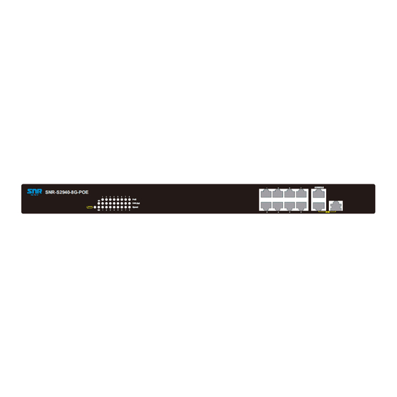
Min. 80, 000 Hours MTBF 1.3 Description of Hardware 1.3.1 Front Panel SNR-S2940-8G-POE has 8 10/100Base-T ports, 1 Combo port (1 RJ-45 and 1 SFP port), 1 Console port and 27 LEDs. The front panel of SNR-S2940-8G-POE is shown as below: Fig 1-2 Front Panel of SNR-S2940-8G-POE 1.3.2 Back Panel... -
Page 4: System Status Indicator Description
SNR-S2940-8G-POE Installation Guide Chapter 1 Introduction Fig 1-4 SNR-S2940-8G-POE LED diagram Table 1-1 SNR-S2940-8G-POE system port indicator description Panel Symbol Status Description On (Green) The port is linked successfully port linked successfully, Port1-8(Link/Act) Flash(Green) receive/send data The port is not link... -
Page 5: Front Panel Port Description
On (Green) The internal power is operating normally Power Power is off or error 1.3.3.3 PoE Indicator Description Fig 1-6 SNR-S2940-8G-POE LED diagram Table 1-3 SNR-S2940-8G-POE system PoE indicator description Status Description Green Port is power on Port is power off 1.3.4 Front Panel Port Description... - Page 6 SNR-S2940-8G-POE Installation Guide Chapter 1 Introduction 550m) • SFP-LX-20-L transcever 1310nm lightwave, 9/125um single mode fiber: 20km • SFP-LX-40 transceiver 9/125um single mode fiber: 40km • SFP-LH-70-L transceiver 9/125um single mode fiber: 70km • SFP-LH-120-L transceiver 9/125um single mode fiber: 120km SFP-GT ...
-
Page 7: Chapter 2 Hardware Installation
2.1.1.1 Dust and Particles Dust is harmful to the safe operation of SNR-S2940-8G-POE. Dust can lead to electrostatic adherence, especially likely under low relative humidity, causing poor contact of metal connectors or contacts. Electrostatic adherence will result in not only reduced product lifespan, but also increased chance of communication failures. -
Page 8: Temperature And Humidity
SNR-S2940-8G-POE Installation Guide Chapter 2 Hardware Installation Table 2-1 Environmental Requirements: Dust content In addition, salt, acid and sulfide in the air are also harmful to the switch. Such harmful gases will aggravate metal corrosion and the aging of some parts. The site should... -
Page 9: Power Supply
SNR-S2940-8G-POE Installation Guide Chapter 2 Hardware Installation operation conditions refers to the ambient temperature and relative humidity value that may occur during an air-conditioning system failure, and normal operation conditions should be recovered within 5 hours. 2.1.1.3 Power Supply It is adopted module switch power for the switch, the input parameters of power are... -
Page 10: Rack Configuration
Caution! If a standard 19’’ rack is not available, the SNR-S2940-8G-POE can be placed on a clean level desktop, leave a clearance of 100mm around the switch for ventilation, and do not place anything on top of the switch. -
Page 11: Installation Preparation
SNR-S2940-8G-POE Installation Guide Chapter 2 Hardware Installation cause physical injury. Do not install, move or disclose the switch and its modules when the switch is in operation. Do not open the switch shell. Do not drop metals into the switch. It can cause short-circuit. -
Page 12: Installation Guide
2.3 Installation Guide 2.3.1 Installing the Switch Please mount the switch as below: 1. Attach the 2 brackets on the SNR-S2940-8G-POE with screws provided in the accessory kit. Fig 2-1 Fasten the Brackets to the Switch 2. Put the bracket-mounted switch smoothly into a standard 19’’ rack. Fasten the SNR-S2940-8G-POE to the rack with the screws provided. -
Page 13: Connecting Console
SNR-S2940-8G-POE Installation Guide Chapter 2 Hardware Installation 2.3.2 Connecting Console SNR-S2940-8G-POE provide a RJ45 serial console port. Fig 2-3 Connecting Console to switch The connection procedure is listed below: Find the console cable provided in the accessory kit. Attach the RJ45 end to console port of the switch. -
Page 14: Ac Power Supply Connection
Do not stare at the fiber bore when the switch is in operation. That may hurt your eyes. 2.3.5 AC Power Supply Connection SNR-S2940-8G-POE use the power is 220VAC. Please read the power input specification for the detailed information. AC Power supply connection procedure is described as below:... -
Page 15: Poe Power Supply Connection
2. Check the power status indicator in the front panel of the switch. The corresponding power indicator should light. SNR-S2940-8G-POE are self-adjustable for the input voltage. As soon as the input voltage is in the range printed on the switch surface, the switch can operate correctly. - Page 16 SNR-S2940-8G-POE Installation Guide Chapter 2 Hardware Installation damaged or malfunction. Please connect the power according to power polarity. When the switch is not powered on or not be enabled, the PoE power supply is shutdown. Do not open the switch shell without permission. It can cause physical injury.
Need help?
Do you have a question about the SNR-S2940-8G-POE and is the answer not in the manual?
Questions and answers