Table of Contents
Advertisement
Quick Links
Advertisement
Table of Contents

Related Manuals for SNR SNR-S2970G-24S


Summary of Contents for SNR SNR-S2970G-24S
- Page 1 SNR-S2970G-24S Hardware Installation Manual...
-
Page 2: Table Of Contents
2.3.3 Cabinet Configuration..........................7 2.3.4 Power Requirements ..........................8 2.4 Installation Tools and Device ..........................8 Chapter 3 Installing the SNR-S2970G-24S Switch ....................... 9 3.1 Installation Flow of SNR-S2970G-24S ........................9 3.2 Installing the Machine Box of the Switch ....................... 9 3.2.1 Installing the Machine Box on the Desk .................... -
Page 3: Chapter 1 Snr-S2970G-24S Introduction
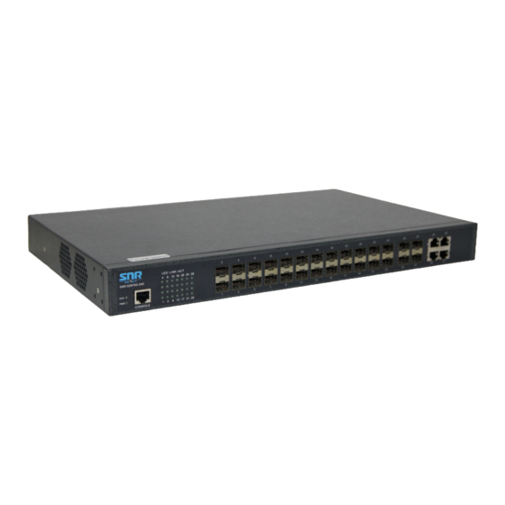
LINK/ACT indicators Console port An RJ45 port with a rate of 9600 bps The SNR-S2970G-24S switch also has a grounding column, one power socket and one on-off at its back. Figure 1-1 Front template of the SNR-S2970G-24S switch Table 1-2 Parts at the front template of the SNR-S2970G-24S switch Abbrev. - Page 4 SNR-S2970G-24S Hardware Installation Manual ports Forward the 1000M-Ethernet optical 24 SFP ports none signals. Figure 1-2 Back template of the SNR-S2970G-24S switch Table 1-3 Parts at the back template of the SNR-S2970G-24S switch Abbrev. Name Description none Grounding The grounding must be fine.
-
Page 5: Characteristic Parameters Of Snr-S2970G-24S
SNR-S2970G-24S Hardware Installation Manual Characteristic Parameters of SNR-S2970G-24S IEEE 802.1d Spanning Tree Protocol IEEE 802.1s multiple spanning trees IEEE 802.1p Class of Service IEEE 802.1q tagged VLAN Supported standard IEEE 802.3x Flow control Prot IEEE 802.3z asymmetric flow control ocol IEEE 802.3ad Link aggregation... -
Page 6: Rohs Description
SNR-S2970G-24S Hardware Installation Manual 1.3 ROHS Description - 4 -... -
Page 7: Chapter 2 Installation Preparation
Similar to other electronic products, the semiconductor chip easily gets damaged if you power on and off abruptly and frequently. To restart up the switch of SNR-S2970G-24S, you have to open the power on-off three or five seconds after the power is cut off. -
Page 8: Safety Principles For Live Working
SNR-S2970G-24S Hardware Installation Manual Pull out the AC power socket and close the direct-current power before operating on the machine box or working beside the power source. The final configuration of products must comply with relative national laws and regulations. -
Page 9: Electrostatic Discharge Prevention
SNR-S2970G-24S Hardware Installation Manual 2.2.4 Electrostatic Discharge Prevention Electrostatic discharge may damage devices and circuits. Improper treatment may cause the switch to malfunction completely or discontinuously. Move or locate the devices according to the measures of electrostatic discharge prevention, ensuring the machine box connects the ground. Another measure is to wear the static-proof hand ring. -
Page 10: Power Requirements
2.4 Installation Tools and Device The tools and devices to install the SNR-S2970G-24S switch are not provided by the SNR-S2970G-24S switch. You yourself need to prepare them. The following are the tools and devices needed for the typical installation of the SNR-S2970G-24S switch: ... -
Page 11: Chapter 3 Installing The Snr-S2970G-24S Switch
SNR-S2970G-24S Hardware Installation Manual Chapter 3 Installing the SNR-S2970G-24S Switch Caution: Only professionals are allowed to install or replace the devices of SNR-S2970G-24S. 3.1 Installation Flow of SNR-S2970G-24S 3.2 Installing the Machine Box of the Switch The installation of the machine box concludes the following cases: ... -
Page 12: Installing The Machine Box On The Desk
SNR-S2970G-24S Hardware Installation Manual 3.2.1 Installing the Machine Box on the Desk The SNR-S2970G-24S switch can be directly put on the smooth and safe desk. Note: Do not put things weighing 4.5 kg or over 4.5 kg on the top of the switch. - Page 13 RJ45 socket, whose pins can be aligned from left to right with the value from 1 to 8. Figure 3-3 RJ-45 connector of the console port Figure 3-4 Connecting the console port of SNR-S2970G-24S and computer Table 3-1 Definition of the pins of the UTP port Name...
-
Page 14: Connecting The 1000M Ethernet Sfp Port
One end of the cable is an 8-pin RJ45 plug and the other end is a 9-hole plug (DB9). The RJ45 plug is put into the socket of the console port on the SNR-S2970G-24S switch. The inner line connection in the cable is shown in figure 3-5. The console cable is numbered as RLC0301. -
Page 15: Connecting The Ethernet Electrical Port
3.3.3 Connecting the Ethernet Electrical Port The SNR-S2970G-24S switch has four 10/100/1000Base-T ports. Each electrical port uses the two indicators corresponding to those of the SFP port, indicating the LINK/ACT state of the port. You can connect other Ethernet terminal devices to the UTP port through the cut-through or cross network cable. -
Page 16: Checking After Installation
SNR-S2970G-24S Hardware Installation Manual Receiving normal RXD1+ Input phase of the data Sending the normal phase TXD2+ Output of the data Sending the paraphase of TXD2- Output the data Receiving the paraphase RXD1- Input of the data Receiving normal RXD2+... -
Page 17: Chapter 4 Maintaining The Switch
SNR-S2970G-24S Hardware Installation Manual Chapter 4 Maintaining the Switch Caution: Before opening the machine box, make sure that you have released the static you carried and then turn off the power on-off of the switch. Before operating any step in Appendix B, read the section “Safety Advice”. -
Page 18: Closing Machine Box
Reinstall the switch on the cabinet or the desk. Reconnect all cables of the switch. 4.3 Memory Upgrade 4.3.1 SDRAM Expansion Because SDRAM of SNR-S2970G-24S adopts the patch design, you have to offer your SDRAM expansion requirement before purchase. - 16 -... -
Page 19: Chapter 5 Hardware Fault Analysis
9600 bps, eight data bits, no sum check bit, one stop bit and no traffic control. 5.2 Indicator Description The LED indicator shows that the switch is running. The following table shows the indicators of the SNR-S2970G-24S switch and their description: - 17 -... - Page 20 SNR-S2970G-24S Hardware Installation Manual Abbrev. Name Description If the switch is powered on, the indicator Power indicator is on. If the indicator is always on, the system is being started. System indicator If the indicator flickers, the system works normally.
Need help?
Do you have a question about the SNR-S2970G-24S and is the answer not in the manual?
Questions and answers