Table of Contents
Advertisement
Quick Links
SNR-S4550-24XQ-AC switch Installation Guide
Introduction ........................................................................... 1-1
1.1 Product Brief ......................................................................................................1-1
1.1.1 Overview ..................................................................................................1-1
1.1.2 Features and Benefits ............................................................................1-1
1.2 Description of Hardware ...................................................................................1-3
1.2.1 Front Panel ..............................................................................................1-3
1.2.2 Back Panel ...............................................................................................1-4
1.3 Status LEDs ........................................................................................................1-4
1.4 Port Description ................................................................................................1-5
1.5 M6000-AC Power Supply Module ....................................................................1-6
1.6 M6000-FAN Fan Module ....................................................................................1-7
1.7 System Specifications ......................................................................................1-7
Installation Notice ................................................................. 2-1
2.1 Environmental Requirements ..........................................................................2-1
2.1.1 Dust and Particles ...................................................................................2-1
2.1.2 Temperature and Humidity .....................................................................2-2
2.1.3 Power Supply ..........................................................................................2-3
2.1.4 Preventing Electrostatic Discharge Damage .......................................2-3
2.1.5 Anti-interference .....................................................................................2-3
2.1.6 Rack Configuration .................................................................................2-3
2.2 Installation Notice ..............................................................................................2-4
2.3 Security Warnings .............................................................................................2-4
Device Installation ................................................................. 3-1
3.1 Installation Preparation .....................................................................................3-1
3.1.1 Verify the Package Contents ..................................................................3-1
3.1.2 Required Tools and Utilities ...................................................................3-1
3.2 Device Installation .............................................................................................3-1
3.2.1 Installing the Switch ...............................................................................3-1
3.2.2 Installing the Power Supply Module .....................................................3-2
3.2.3 Installing the Fan .....................................................................................3-3
3.2.4 Connecting Console ...............................................................................3-4
3.2.5 SFP/SFP+/QSFP+ Transceiver Installation ...........................................3-5
3.2.6 Copper Cable/Fiber Cable Connection .................................................3-5
3.2.7 AC Power Supply Connection ...............................................................3-7
3.2.8 Earthing Cable Connection ....................................................................3-8
3.2.9 Checking the Switch ...............................................................................3-9
Content
1
Content
Advertisement
Table of Contents

Related Manuals for SNR SNR-S4550-24XQ-AC


Summary of Contents for SNR SNR-S4550-24XQ-AC
-
Page 1: Table Of Contents
SNR-S4550-24XQ-AC switch Installation Guide Content Content Chapter 1 Introduction ................1-1 1.1 Product Brief ......................1-1 1.1.1 Overview ....................1-1 1.1.2 Features and Benefits ................1-1 1.2 Description of Hardware ...................1-3 1.2.1 Front Panel ....................1-3 1.2.2 Back Panel ....................1-4 1.3 Status LEDs ......................1-4 1.4 Port Description ....................1-5... -
Page 2: Chapter 1 Introduction
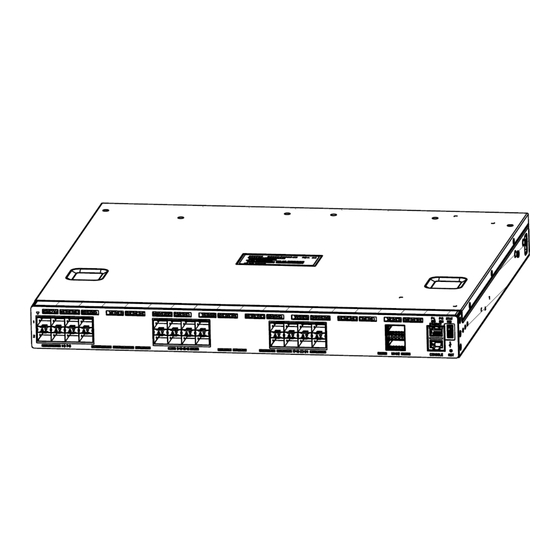
IP metropolitan networks; as well as core layer switches for small and medium-sized networks. 1.1.2 Features and Benefits Various Interfaces SNR-S4550-24XQ-AC switch provides 24 10Gb SFP+ ports and 2 40Gb ports of QSFP+ ports. Each QSFP+ port can be split into 4 10Gb SFP+ ports. - Page 3 10Gb Ethernet which adopts full-duplex technology instead of low-speed, half-duplex CSMA/CD protocol, is a big leap in the evolution of Ethernet. 10Gb Ethernet can be deployed in star or ring topologies. With 10Gb Ethernet, SNR-S4550-24XQ-AC switch provides broad bandwidth and powerful processing capacity. It is suitable for metropolitan networks and wide area networks.
-
Page 4: Description Of Hardware
IPv6 and MPLS implement high-performance wire speed forward at the same time, and provides more help for building the grand IP network. SNR-S4550-24XQ-AC supports LDP function and MPLS VPN (it can acce ss the public network), and it can be deployed as PE and P. -
Page 5: Back Panel
Fig 1-4 Back panel of SNR-S4550-24XQ-AC (full in) 1.3 Status LEDs The indicator light on front panel of SNR-S4550-24XQ-AC has 24 SFP+ port indicator light, 2 QSFP+ port indicator light, 2 power supply indicator light and system automatic diagnoses LED. They are shown below and described in the following table. -
Page 6: Port Description
QSFP+ port Wink The port is transmitting data. Put out No connection or fail to connect. 1.4 Port Description SNR-S4550-24XQ-AC provides 24 10G SFP+ ports and 2 40Gb QSFP+ ports. SNR-S4550-24XQ-AC switch supports the following SFP transceivers: SFP-SX-L transceiver SFP-LX-L transceiver ... -
Page 7: M6000-Ac Power Supply Module
QSFP+ 40GBASE-SR4 transceiver 850nm, MMF, OM3/OM4, 100m SNR-S4550-24XQ-AC provides 2 QSFP+ ports and supports the QSFP+ cable. It enhances the flexibility of the network. User can select the cables according to the demand. 1.5 M6000-AC Power Supply Module M6000-AC is the power supply module of SNR-S4550-24XQ-AC. The whole... -
Page 8: M6000-Fan Fan Module
SNR-S4550-24XQ-AC switch Installation Guide Chapter 1 Introduction 1.6 M6000-FAN Fan Module M6000-FAN is the fan module of SNR-S4550-24XQ-AC. The whole appearance sketch map is below: Fig 1-6 The sketch map of M6000-FAN SNR-S4550-24XQ-AC switch has 5 M6000-FAN in standard configuration. The rotate speed of fan adjusts itself adapt to the system temperature. -
Page 9: Chapter 2 Installation Notice
2.1.1 Dust and Particles Dust is harmful to the safe operation of SNR-S4550-24XQ-AC. Dust can lead to electrostatic adherence, especially likely under low relative humidity, causing poor contact of metal connectors or contacts. Electrostatic adherence will result in not only reduced product lifespan, but also increased chance of communication failures. -
Page 10: Temperature And Humidity
SNR-S4550-24XQ-AC switch Installation Guide Chapter 2 Installation Notice Average (mg/m³) Max (mg/m³) 0.006 0.03 0.04 0.15 0.05 0.15 0.01 Table 2-2 Environmental Requirements: Particles 2.1.2 Temperature and Humidity Although the switch is designed to use 5 fans, the site should still maintain a desirable temperature and humidity. -
Page 11: Power Supply
SNR-S4550-24XQ-AC switch Installation Guide Chapter 2 Installation Notice 2.1.3 Power Supply Before powering on the power supply, please check the power input to ensure proper grounding of the power supply system. The input source for the switch should be reliable and secure;... -
Page 12: Installation Notice
Caution! If a standard 19’’ rack is not available, the SNR-S4550-24XQ-AC can be placed on a clean level desktop, leave a clearance of 100mm around the switch for ventilation, and do not place anything on top of the switch. - Page 13 SNR-S4550-24XQ-AC switch Installation Guide Chapter 2 Installation Notice Have the emergence power switch on the site. In case of emergence, switch off the power immediately. Caution! Potential risk include: Electric leakage, Power supply arcing, Power line breakage, Imperfect earth, Overload circuit and Electrical short circuit. If electric shock, fire, electrical short circuit occurs, please cut off the electricity supply and alarm rapidly.
-
Page 14: Chapter 3 Device Installation
Antistatic uniform Caution! Users should prepare the required tools and utilities by themselves. 3.2 Device Installation 3.2.1 Installing the Switch Figure 3-1 SNR-S4550-24XQ-AC switch install sketch map on the rack using stock Please mount SNR-S4550-24XQ-AC on the 19’’ rack as below:... -
Page 15: Installing The Power Supply Module
There is no back horn iron in standard configuration. If users bought it, the figure of installation is below: Figure 3-2 The figure of SNR-S4550-24XQ-AC switch installing on the rack by using the front and back horn iron 3.2.2 Installing the Power Supply Module... -
Page 16: Installing The Fan
SNR-S4550-24XQ-AC switch Installation Guide Chapter 3 Device Installation Figure 3-3 The figure of SNR-S4550-24XQ-AC switch power supply installing Please install the power supply module according to the following approach: Take out the power supply module from the little packing box. -
Page 17: Connecting Console
Chapter 3 Device Installation Figure 3-4 The figure of SNR-S4550-24XQ-AC switch installing the fan Please install the fan module according to the following approach: The golden finger is inward and adown and aim at the fan rabbet of the back machine flatly to the end. -
Page 18: Sfp/Sfp+/Qsfp+ Transceiver Installation
Power on the switch and the character terminal. Configure the switch through the character terminal. 3.2.5 SFP/SFP+/QSFP+ Transceiver Installation SNR-S4550-24XQ-AC provides 24 SFP/SFP+ transceiver slots and 2 QSFP+ ports. The procedure for installing the SFP/SFP+/QSFP+ transceiver is shown below: Step 1: Put on a ESD wrist strap (or antistatic gloves) Step 2: Insert the SFP/SFP+/QSFP+ transceiver to the guide rail inside the SFP/SFP+/QSFP+ port. - Page 19 SNR-S4550-24XQ-AC switch Installation Guide Chapter 3 Device Installation Copper cables should be connected as below: Step 1: Insert one end of the Ethernet cable to the RJ-45 Ethernet port in the switch copper port; Step 2: Insert the other end of the Ethernet cable to the RJ-45 Ethernet port of other device;...
-
Page 20: Ac Power Supply Connection
If LINK light puts out, it means the lines have trouble and please check out the line connection. 3.2.7 AC Power Supply Connection SNR-S4550-24XQ-AC uses 220VAC power supply by default. Please read the power input specification for the detailed information. -
Page 21: Earthing Cable Connection
Chapter 3 Device Installation Figure 3-7 Connect the power supply cable to the SNR-S4550-24XQ-AC switch AC Power supply connection procedure is described as below: 1. Insert one end of the power cable provided in the accessory kit into power source socket, and the other end to the power socket (with overload and leakage protection). -
Page 22: Checking The Switch
SNR-S4550-24XQ-AC switch Installation Guide Chapter 3 Device Installation Figure 3-8 Connect the earthing cable to the SNR-S4550-24XQ-AC switch Please connect the earthing cable according to the following approach: Screw out the fixed nut on the earthing pillar of the switch.
Need help?
Do you have a question about the SNR-S4550-24XQ-AC and is the answer not in the manual?
Questions and answers