Table of Contents
Advertisement
Quick Links
Advertisement
Table of Contents

Related Manuals for SNR SNR-S212i-8POE Series


Summary of Contents for SNR SNR-S212i-8POE Series
- Page 1 SNR-S212i-8POE Installation Guide...
- Page 2 NAG LLC provides customers with comprehensive technical support and services. For any assistance, please contact office Website: http://shop.nag.ru Tel: +7 343 3799838 Email: support@nag.com Address: 57/2 Predelnaya st., Ekaterinburg, Russia Postal code: 620016 ----------------------------------------------------------------------------------------------------------------------------- ------------...
- Page 3 SNR-S212i-8POE Installation Guide Preface Preface Objectives This document describes overview, hardware structure, technical specifications, hardware installation, networking applications, and management and maintenance of the network- manageable guide-rail Layer 2 PoE industrial Ethernet switch. The appendix lists compliant standards and protocols, terms, acronyms, and abbreviations involved in this document.
- Page 4 SNR-S212i-8POE Installation Guide Preface General conventions Convention Description Times New Roman Normal paragraphs are in Times New Roman. Arial Paragraphs in Warning, Caution, Notes, and Tip are in Arial. Boldface Names of files, directories, folders, and users are in boldface.
-
Page 5: Table Of Contents
SNR-S212i-8POE Installation Guide Contents Contents 1 Overview ..........................1-1 1.1 Introduction ............................1-1 1.2 Characteristics ............................1-1 1.2.1 Outstanding industrial features ....................... 1-1 1.2.2 Rich product types ......................... 1-2 1.2.3 Powerful PoE power supply ......................1-2 1.2.4 Flexible networking ........................1-2 1.2.5 Strict QoS ............................ - Page 6 SNR-S212i-8POE Installation Guide Contents 2.7 Cables ..............................15 2.7.1 Console cable ..........................15 2.7.2 Ethernet cable ..........................16 2.7.3 AC power cable ..........................19 2.7.4 DC power cable ..........................21 2.7.5 Grounding cable ..........................22 2.7.6 Alarm cable .............................24 2.7.7 Digital input cable ...........................25 3 Technical specifications ......................27 3.1 Overall parameters............................27...
- Page 7 SNR-S212i-8POE Installation Guide Contents 5.2.7 Watchdog ............................42 5.2.8 Port mirroring ..........................42 6 Appendix ..........................43 6.1 Terms ...............................43 6.2 Acronyms and abbreviations ........................48 Shop.Nag.Ru 2016...
- Page 8 Figures Figure 2-1 Front appearance ..........................6 Figure 2-2 Side appearance ..........................7 Figure 2-3 Top appearance of the SNR-S212i-8POE DC ................8 Figure 2-4 Rear appearance ..........................9 Figure 2-5 AC power interface ........................13 Figure 2-6 DC power interface ........................14 Figure 2-7 RJ45 Console cable ........................15...
- Page 9 SNR-S212i-8POE Installation Guide Tables Tables Table 1-1 Models............................1-4 Table 2-1 Interfaces ............................9 Table 2-1 Management and auxiliary interfaces ....................10 Table 2-2 Reset button ............................10 Table 2-3 Parameters of the 1000BASE-X SFP optical interface ..............11 Table 2-4 Parameters of the 100BASE-FX SFP optical interface ..............11 Table 2-5 Parameters of the 10/100BASE-TX RJ45 electrical interface ............
- Page 10 SNR-S212i-8POE Installation Guide Tables Table 3-1 Overall parameters ..........................27 Table 3-2 PoE power supply ...........................28 Table 3-3 Environment standard requirements ....................29 Table 4-1 Power supply requirements for operation ..................30 Table 4-2 Check after installation........................37 Shop.Nag.Ru 2016...
-
Page 11: Overview
SNR-S212i-8POE Installation Guide Overview Overview This chapter is an overview of the SNR-S212i-8POE, including the following sections: Introduction Characteristics Models 1.1 Introduction The network-manageable guide-rail Layer 2 PoE industrial Ethernet switch SNR-S212i-8POE (hereinafter referred to as the SNR-S212i-8POE) adopts a guide-rail chassis, with all-metal shell and fan-free design for heat dissipation (with cooling fin). -
Page 12: Rich Product Types
Support a Mean Time Between Failure (MTBF) of 35 years. 1.2.2 Rich product types The SNR-S212i-8POE, with flexible interface configurations, can meet special industrial environment requirements, with the following characteristics: Provide 8 RJ45 electrical interfaces and 4 SFP optical interfaces. -
Page 13: Complete Security Guarantee
Support IEEE 802.1x security access control. Support storm control (over broadcast packets, unknown multicast packets, and unknown unicast packets), thus effectively guaranteeing proper operation of the SNR- S212i-8POE in bad network conditions. Support IEEE 802.1Q interface-based VLAN partitioning to implement isolation of physical interfaces. -
Page 14: Table 1-1 Models
SNR-S212i-8POE Installation Guide Overview Table 1-1 Models Model Description Support eight 10/100 Mbit/s Ethernet electrical interfaces, SNR-S212i-8POE-AC support IEEE 802.3af and IEEE 802.3at, and non-standard PDs. It supports up to 8 interfaces with 15.54 W power on each interface or up to 4 interfaces with 30 W power on each interface. -
Page 15: Hardware Structure
SNR-S212i-8POE Installation Guide Hardware structure Hardware structure This chapter describes hardware structure of the SNR-S212i-8POE, including the following sections: Appearance Interfaces Reset button Interface parameters LEDs Power modules Cables 2.1 Appearance The dimensions of the chassis is 98 mm (Width) -
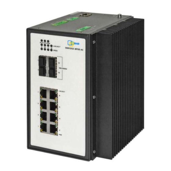
Page 16: Figure 2-1 Front Appearance
SNR-S212i-8POE Installation Guide Hardware structure Figure 2-1 Front appearance LEDs (ALM, SYS, PWR, LNK/ACT, and SPD) Service interfaces 9 12 (100/1000 Mbit/s SFP optical interface) Service interfaces 1 8 (100 Mbit/s electrical interface, supporting PoE) and LEDs LNK/ACT and POE) -
Page 17: Side Appearance
SNR-S212i-8POE Installation Guide Hardware structure 2.1.2 Side appearance Figure 2-2 shows side appearance of the SNR-S212i-8POE. Figure 2-2 Side appearance 2.1.3 Top appearance 0 and Figure 2-3 show the top appearance of the SNR-S212i-8POE Top appearance of the SNR-S212i-8POE-AC Shop.Nag.Ru 2016... -
Page 18: Rear Appearance
2 RST button 3 Alarm interface (ALM) 4 Digital input interface 5 Grounding terminal 6 AC power interface (PWR) Figure 2-3 Top appearance of the SNR-S212i-8POE DC 1 Console interface 2 RST button 3 Alarm interface (ALM) 4 Digital input interface... -
Page 19: Interfaces
1 Clamping connector 2 Sliding connector 2.2 Interfaces 2.2.1 Service interfaces The SNR-S212i-8POE provides four 1000 Mbit/s SFP optical interfaces and eight 100 Mbit/s PoE RJ45 electrical interfaces. Table 2-1 lists types and usage of interfaces on the SNR-S212i-8POE. Table 2-1 Interfaces... -
Page 20: Management And Auxiliary Interfaces
SNR-S212i-8POE Installation Guide Hardware structure 2.2.2 Management and auxiliary interfaces Table 2-1 lists management and auxiliary interfaces on the SNR-S212i-8POE. Table 2-1 Management and auxiliary interfaces Interface Description Console Use the RJ45 Console cable to connect to the PC. Alarm interface (ALM) 3-PIN Phoenix terminal (5.08 mm space) for outputting... -
Page 21: 100Base-Fx Sfp Optical Interface
SNR-S212i-8POE Installation Guide Hardware structure Table 2-3 Parameters of the 1000BASE-X SFP optical interface Parameter Description Connector type LC/PC Optical interface properties Depend on the selected SFP optical module. Coding type 8B/10B Working mode Full duplex Compliant standard IEEE 802.3 Supported network protocol 2.4.2 100BASE-FX SFP optical interface... -
Page 22: Console Interface
Working mode Duplex UART Electrical feature RS-232 Baud rate 9600 Baud Cable specification 4-core shielded cable 2.5 LEDs Table 2-7 lists LEDs on the SNR-S212i-8POE. Table 2-7 LEDs Print Status Description Green: the electrical interface is in Electrical LNK/ACT Green Link Up status. -
Page 23: Power Modules
The AC or DC power interface is a 7.62 mm 3-PIN Phoenix terminal interface. AC power interface Figure 2-5 shows the AC power interface. Figure 2-5 AC power interface Table 2-8 describes the AC power interface on the top of the SNR-S212i-8POE. Shop.Nag.Ru 2016... -
Page 24: Specifications
L-wire terminal connecting to the AC power DC power interface Figure 2-6 shows the DC power interface. Figure 2-6 DC power interface Table 2-9 describes the DC power interface on the top of the SNR-S212i-8POE. Table 2-9 DC power interface Power module Print... -
Page 25: Cables
2.7.1 Console cable Introduction With the Console cable, you can log in to the SNR-S212i-8POE through the Console interface, and then debug and maintain it from a PC. The RJ45 Console cable is an 8-core unshielded cable, with connectors as below:... -
Page 26: Ethernet Cable
Number of cores Length 2.7.2 Ethernet cable Introduction For the SNR-S212i-8POE, the Ethernet cable connects the Ethernet electrical interface and other devices. The Ethernet interface on the SNR-S212i-8POE is self-adaptive to straight-through cable mode and crossover cable mode. If required, make the Ethernet cable on site according to technical specifications. -
Page 27: Figure 2-9 Ethernet Cable
SNR-S212i-8POE Installation Guide Hardware structure Figure 2-9 Ethernet cable Technical specifications The Ethernet cables have two types: Straight-through cable: used to connect devices of different type, such as between a PC and a switch, between a switch and a router... -
Page 28: Figure 2-10 Wiring Of The Straight-Through Cable
SNR-S212i-8POE Installation Guide Hardware structure Straight-through cable Both two RJ45 connectors of the straight-through cable follow EIA/TIA568 B standard wiring. Figure 2-10 shows the wiring of the straight-through cable. Figure 2-10 Wiring of the straight-through cable Crossover cable The wiring of the 100 Mbit/s crossover cable is different from that of the 1000 Mbit/s crossover cable. -
Page 29: Ac Power Cable
The AC power cable supplies 110 V/220 V AC power from the power souring equipment to the power interface on the SNR-S212i-8POE, and then transmits power to the entire device. The AC power cables of the SNR-S212i-8POE are different according to regional standards. -
Page 30: Table 2-15 European Standard Ac Power Cable
SNR-S212i-8POE Installation Guide Hardware structure Table 2-15 European standard AC power cable The AC power cable which meets American standard is composed of the American standard 3-pin plug and coaxial cable, as shown in Table 2-16. Table 2-16 American standard AC power cable Technical specifications Table 2-17 lists specifications of the European standard AC power cable. -
Page 31: Dc Power Cable
Introduction The DC power cable supplies 48 VDC power from the power souring equipment to the power interface on the SNR-S212i-8POE, and then transmits power to the entire device. Appearance The DC power cable is composed of a connector and conducting wire, as shown in Figure 2-... -
Page 32: Grounding Cable
The grounding cable is used to connect the SNR-S212i-8POE to the ground. Appearance The grounding cable is composed of grounding terminals and the coaxial cable. The grounding terminal is usually an OT non-insulated terminal. -
Page 33: Table 2-20 Technical Specifications Of The Grounding Cable
Thickness of soldering lug: 0.6 mm Cross-sectional area of 16 15 AWG (1.2 1.5 mm the conducting wire The SNR-S212i-8POE is delivered without the grounding cable. If required, make the grounding cable on site according to technical specifications. Shop.Nag.Ru 2016... -
Page 34: Alarm Cable
2.7.6 Alarm cable Introduction The alarm interface on the SNR-S212i-8POE is a 3-PIN Phoenix terminal interface (5.08 mm space). When the SNR-S212i-8POE is in abnormal status (temperature, voltage, etc.), it can output alarms through the control terminal to the on-site maintenance personnel and the NMS. -
Page 35: Digital Input Cable
2.7.7 Digital input cable Introduction The digital input interface on the SNR-S212i-8POE uses 4 PINs of the 5-PIN Phoenix terminal (5.08 mm space) to input external alarms from an external device. The digital input interfaces supports dual way input. Each way supports two statuses: Status 1: the input voltage is 13 30 V. -
Page 36: Table 2-24 Technical Specifications Of The Digital Input Cable
Table 2-24 Technical specifications of the digital input cable Item Description Connector 5.08-8Pin-head/RoHS Specifications Copper core multi-strand conducting wire 18AWG (0.75 mm The digital input cable is not delivered with the SNR-S212i-8POE. If you need it, make it on site according to technical specifications. Shop.Nag.Ru 2016... -
Page 37: Technical Specifications
SNR-S212i-8POE Installation Guide Technical specifications Technical specifications This chapter describes technical specifications of the SNR-S212i-8POE, including the following sections: Overall parameters PoE power EMC standards Environmental standards 3.1 Overall parameters Table 3-1 lists overall parameters of the SNR-S212i-8POE. Table 3-1 Overall parameters... -
Page 38: Poe Power
55 60 C 65 W 70 75 C 60 65 C 35 W > 75 C > 65 C 3.3 EMC standards The SNR-S212i-8POE complies with the following EMC standards. Electro Magnetic Interference (EMI): CISPR 22 CLASS A Shop.Nag.Ru 2016... -
Page 39: Environmental Standards
Conduction noise immunity: IEC 61000-4-6 level 3 AC voltage DIPS and short interruptions noise immunity: IEC 61000-4-29 3.4 Environmental standards The SNR-S212i-8POE is applied to an industrial environment, with environmental standards requirements as listed in Table 3-3. Table 3-3 Environment standard requirements... -
Page 40: Hardware Installation
The switch supports the following installation modes: Guide-rail installation Wall-mounting installation Before installing the SNR-S212i-8POE, ensure that the environment where the SNR- S212i-8POE is to be installed complies with environment requirements. For details, see section 3.4 Environmental standards. 4.1.2 Power supply conditions Table 4-1 lists power supply requirements for operation of the SNR-S212i-8POE. -
Page 41: Static Electricity Conditions
4.2 Installing device 4.2.1 Guide-rail installation When you take the SNR-S212i-8POE from the package, it is installed with a guide- rail kit at its rear panel. Install the SNR-S212i-8POE on the guide rail as below: Step 1 Hang the sliding connector on the guide rail. -
Page 42: Wall-Mounting Installation
Step 3 Check whether the sliding connector is properly installed on the guide rail. 4.2.2 Wall-mounting installation Before install the SNR-S212i-8POE on the wall, remove the rail-clamping kit from the SNR-S212i-8POE. The wall-mount plane is not delivered with the SNR-S212i-8POE. Purchase one if needed. -
Page 43: Figure 4-3 Removing The Rail-Clamping Kit
Hardware installation Figure 4-3 Removing the rail-clamping kit Step 2 Install the wall-mount plane against the rear panel of the SNR-S212i-8POE, and fasten screws clockwise, as shown in Figure 4-4. Figure 4-4 Installing the wall-mount plane against the rear panel Step 3 Install the wall-mount plane on the wall. -
Page 44: Grounding Device
SNR-S212i-8POE Installation Guide Hardware installation Figure 4-5 Installing the wall-mount plane on the wall 4.3 Grounding device Connecting the grounding cable properly is an important guarantee to lightning protection, shock proof, and anti-interference. When installing and using the device, ensure that the grounding cable is properly connected; otherwise, personnel injury or equipment damage may be caused. -
Page 45: Connecting Cables
Step 1 Choose a proper length for the Ethernet cable according to cabling path, and make an Ethernet cable accordingly. Step 2 Insert the RJ45 connector of the Ethernet cable into the Ethernet interface of the SNR-S212i- 8POE, as shown in Figure 4-8. -
Page 46: Connecting Power
SNR-S212i-8POE. There is invisible laser inside the SNR-S212i-8POE and it harms eyes. Do not directly stare into the optical interface, fiber connector, or breakage of fiber. -
Page 47: Powering On Device
Step 2 After self-check and initialization, the SNR-S212i-8POE enters the working status. The interface LED indicates the working status (Green, Blinking green, or Off). 4.6 Check after installation After installation is complete, check the SNR-S212i-8POE and environment as listed in Table 4-2. Table 4-2 Check after installation... - Page 48 SNR-S212i-8POE Installation Guide Hardware installation Item Method Space for heat dissipation is reserved around the device. No heavy object is laid on View. the device. Shop.Nag.Ru 2016...
-
Page 49: Management And Maintenance
Internet. Applied with the Telnet protocol, a local PC can be a terminal for the remote host system. You can log in to the SNR-S212i-8POE through the PC which runs the Telnet program. You can type commands through Telnet, and these commands will be executed on the SNR-S212i-8POE as you directly execute commands on the SNR-S212i-8POE. -
Page 50: Web Mode
The network management system can visit the agent only by specifying its community name correctly. If the community name carried in a SNMP packet is not accepted by the SNR-S212i-8POE, the packet will be dropped. -
Page 51: Traceroute
The system log refers that the SNR-S212i-8POE records the system information and debugging information in a log and sends the log to the specified destination. When the SNR- S212i-8POE fails to work, you can check and locate the fault easily. -
Page 52: Watchdog
Internal voltage Tx bias current Tx optical power Rx optical power With this function, you can globally configure optical modules on the SNR-S212i-8POE, view and export the following tables: Optical module information table Optical module detection table Optical module current period detection table Optical module period detection table. -
Page 53: Appendix
Appendix This chapter lists terms, acronyms, and abbreviations involved in this document, including the following sections: Terms Acronyms and abbreviations 6.1 Terms A series of ordered rules composed of permit | deny sentences. These Access rules are based on the source MAC address, destination MAC address, Control List source IP address, destination IP address, interface ID, etc. - Page 54 CHAP is a widely supported authentication method in which a representation of the user's password, rather than the password itself, is sent during the authentication process. With CHAP, the remote access server sends a challenge to the remote access client. The remote access client uses a hash algorithm (also known as a hash function) to compute Challenge a Message Digest-5 (MD5) hash result based on the challenge and a...
- Page 55 Generic Framing Procedure (GFP) is a generic mapping technology. It can group variable-length or fixed-length data for unified adaption, encapsulation making data services transmitted through multiple high-speed physical transmission channels. Half duplex In a communication link, both parties can receive or send data at a time. Institute of A professional society serving electrical engineers through its Electrical and...
- Page 56 Multi-mode In this fiber, multi-mode optical signals are transmitted. fiber A time synchronization protocol defined by RFC1305. It is used to synchronize time between distributed time server and clients. NTP is Network Time used to perform clock synchronization on all devices that have clocks in Protocol the network.
- Page 57 802.1Q in 802.1Q (QinQ), also called Stacked VLAN or Double VLAN, is extended from 802.1Q and defined by IEEE 802.1ad recommendation. This VLAN feature allows the equipment to add a VLAN tag to a tagged packet. The implementation of QinQ is to add a public VLAN tag to a packet with a private VLAN tag, making the packet encapsulated with QinQ two layers of VLAN tags.
-
Page 58: Acronyms And Abbreviations
VLAN is a protocol proposed to solve broadcast and security issues for Virtual Local Ethernet. It divides devices in a LAN into different segments logically Area Network rather than physically, thus implementing multiple virtual work groups (VLAN) which are based on Layer 2 isolation and do not affect each other. VLAN mapping is mainly used to replace the private VLAN Tag of the Ethernet service packet with the ISP's VLAN Tag, making the packet transmitted according to ISP's VLAN forwarding rules. - Page 59 Customer Edge CHAP Challenge Handshake Authentication Protocol CIDR Classless Inter-Domain Routing Committed Information Rate CIST Common Internal Spanning Tree Command Line Interface Class of Service Central Processing Unit Cyclic Redundancy Check CSMA/CD Carrier Sense Multiple Access/Collision Detection Common Spanning Tree Dynamic ARP Inspection Dynamic Bandwidth Allocation Direct Current...
- Page 60 File Transfer Protocol GARP Generic Attribute Registration Protocol Gigabit Ethernet GMRP GARP Multicast Registration Protocol Global Positioning System GVRP Generic VLAN Registration Protocol HDLC High-level Data Link Control HTTP Hyper Text Transfer Protocol IANA Internet Assigned Numbers Authority ICMP Internet Control Message Protocol Internet Explorer International Electro technical Commission IEEE...
- Page 61 Medium Access Control Medium Dependent Interface MDI-X Medium Dependent Interface cross-over Management Information Base MSTI Multiple Spanning Tree Instance MSTP Multiple Spanning Tree Protocol MTBF Mean Time Between Failure Maximum Transmission Unit Multicast VLAN Registration Network Management System Network Node Management Network Time Protocol Operation, Administration, and Management Ordinary Clock...
- Page 62 PPPoE PPP over Ethernet Precision Time Protocol Quality of Service RADIUS Remote Authentication Dial In User Service Random Early Detection Relative Humidity Routing Information Protocol RMON Remote Network Monitoring Ring Protection Link RRPS Redundant Ring Protection Switching RSTP Rapid Spanning Tree Protocol RSVP Resource Reservation Protocol SCADA...
- Page 63 Type of Service TPID Tag Protocol Identifier Time To Live User Datagram Protocol User-Based Security Model VLAN Virtual Local Area Network Wide Area Network Weight Round Robin...
Need help?
Do you have a question about the SNR-S212i-8POE Series and is the answer not in the manual?
Questions and answers