Table of Contents
Advertisement
Quick Links
Advertisement
Table of Contents

Related Manuals for ACU-RITE CSS I/O


Summary of Contents for ACU-RITE CSS I/O
- Page 1 ACU-RITE ® User’s Manual CSS I/O English (en) 10/2009...
-
Page 3: Table Of Contents
Configuration of CSS ..15 CSS operating mode ..16 Activating the DAC output ..17 Connecting the CSS I/O to the inverter of the lathe ..18 I - 4 Diagnostics ..19 General Information ..19 Switching I/O functions ..19 CSS, and Mill Spindle .. -
Page 5: I Operating Instructions
Operating Instructions CSS I/O... -
Page 6: General Information
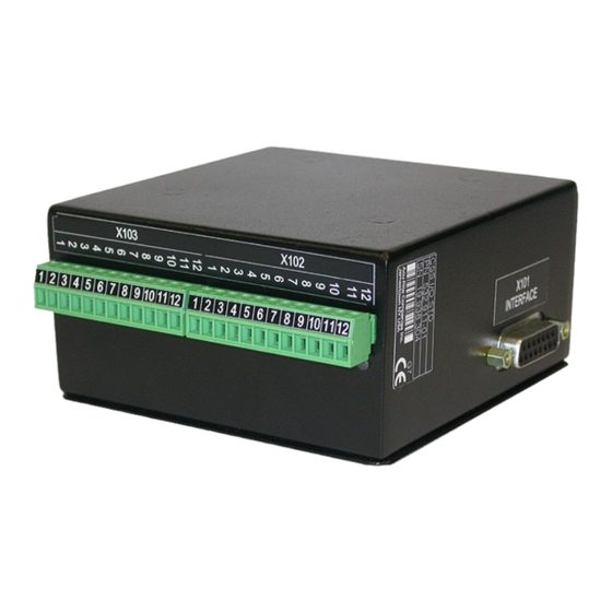
Connecting the CSS I/O to X101 for executing switching functions (milling) or controlling the constant surface speed CSS (turning) When the CSS I/O is connected to DRO’s that support this feature, the functionality described above are available. Contact an authorized Acu-Rite product distributor for more information. -
Page 7: Execution Of Switching Functions
I - 1 Execution of Switching Functions If you want to use both the CSS I/O and the KT 130 edge finder at the same time or if you want to transmit measured values via the external switching output, the distribution cable with ID 593761-01 is required. - Page 8 The CONDITION field is used to assign an axis to the output and to specify whether the axis position is an actual-value or distance-to-go position. You also specify the position display value at which the relay is activated, and the required condition. The POINT/RANGE field is used to define whether the conditions refers to a point on the axis or refers to a range about zero.
- Page 9 FALSE to TRUE. If the switching conditions transitions to TRUE before the period has timed out, the timer will start over. The switching functions cannot be used for coupled axes or for axes with backlash compensation. Relay Pulsed mode shown: Condition CSS I/O...
-
Page 10: Spindle Speed Control (Rpm)
The Mill Spindle Speed Control is for milling systems only, and provides an open loop spindle speed control. The spindle speed control requires the CSS I/O box. The spindle speed control is only available for milling systems. If the DRO is configured for a turning system, then no Spindle Settings will be displayed. -
Page 11: Display
Mill Spindle Installation setup The configuration parameters are found under Installation Setup. The Spindle Settings only appear in the list if the CSS I/O box is detected. Select Spindle Settings from the Installation Setup menu, and press the ENTER key. -
Page 12: Voltage / Rpm Setup
Voltage / RPM Setup The voltage setup fields are used to establish the relationship between the DAC output signal (0 - 10 V), and the spindle speed for each gear. Enter min, and max voltage levels for each gear. Press ENTER to save the settings, and exit the form, or press the C key to exit without saving the changes. -
Page 13: Voltage Offset / Rpm Source
These are run time limits, and must fit in within the actual hardware limits. Press ENTER to save the settings, and exit the form, or press the C key to exit without saving the changes. CSS I/O... -
Page 14: Operation / Job Execution
Operation / Job Execution The operation of the Mill Spindle is associated with the use of the selected tool from the tool table, and the spindle parameters for running the tool. Refer to the DRO User’s Manual for setting up, and using a tool from the tool table. -
Page 15: Mill Spindle Feature Run
To go back to the program control screen from the mill spindle control, press the LEFT, or RIGHT ARROW keys. The speed of the mill spindle can also be adjusted while in the program control screen by pressing the SPEED +/- soft keys. CSS I/O... -
Page 16: Controlling The Constant Surface Speed (Css)
DAC output signal. The READY output (X103-12) is active when the readout has recognized the CSS I/O hardware, is monitoring the inputs, and is controlling the output relays. If the CSS I/O detects a communications error with the readout, the READY relay will be de- energized. -
Page 17: Configuration Of Css
V = 10 · (S ) / (S ) + V Offset Press ENTER to save the parameters and exit the input form. Press the C key to exit without saving the changes you made. CSS I/O... -
Page 18: Css Operating Mode
CSS operating mode The operating parameters are set in the CSS / DIRECT RPM form. Press the CSS SETUP soft key to open the form or select the parameter from the JOB SETUP menu. The SETTINGS field is used to select the mode of operation and the control settings. -
Page 19: Activating The Dac Output
The SPEED + and SPEED – soft keys are used to increase or decrease the current surface speed or spindle speed. The value is increased or decreased by 5% each time the soft key is pressed. CSS I/O... -
Page 20: Connecting The Css I/O To The Inverter Of The Lathe
Connecting the CSS I/O to the inverter of the lathe Example of gear detection and switching to manual spindle speed control Example of switching to manual spindle speed control I Operating Instructions... -
Page 21: I - 4 Diagnostics
All currently active relay outputs (1 to 9) are shown in the OFF field. The CALIBRATE soft key is used to re-synchronize the communication with the CSS I/O. This, however, is only required if the module is not detected upon power on. -
Page 22: Css, And Mill Spindle
The state of the switching inputs and outputs is also shown. The CAN STATUS field shows the state of the bus communication between the DRO, and the CSS I/O. The status information has the following meaning: Information... - Page 23 Potentiometer relay is active (X102-10) DAC output relay is active (X102-11) The CALIBRATE soft key is used to re-synchronize the communication with the CSS I/O. This, however, is only required if the module was not detected at switch-on. CSS I/O...
- Page 24 I Operating Instructions...
- Page 25 Configuration of CSS ... 9, 15 Connecting the CSS I/O to the inverter of the lathe ... 18 Connecting the CSS I/O to X101 ... 4 Controlling the constant surface speed (CSS) ... 8, 14 CSS, and Mill Spindle ... 20 CSS DIAGNOSTICS ...
- Page 28 HEIDENHAIN CORPORATION 333 East State Parkway Schaumburg, IL 60173-5337 USA +1 (847) 490-1191 +1 (847) 490-3931 E-Mail: info@heidenhain.com www.heidenhain.com 638296-21 Ver 01 01/2010...
Need help?
Do you have a question about the CSS I/O and is the answer not in the manual?
Questions and answers