Advertisement
Quick Links
Advertisement

Related Manuals for ACU-RITE SENC 50


Summary of Contents for ACU-RITE SENC 50
- Page 1 Digital Readouts Linear Encoders For Manually-Operated Machine Tools 04/2019...
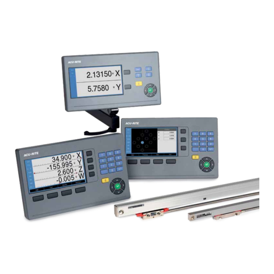
- Page 2 Digital readouts from ACU-RITE make your manually operated machine tools more profitable, improve productivity and raise the quality of the machined workpiece. The 7" TFT color flat panel display shows the actual axis position lucidly and clearly. The context- sensitive graphical user guidance makes working with digital readouts from ACU-RITE a pleasure.
- Page 3 IOB 610 external input/output unit for DRO300 Interfaces Linear encoders Linear encoders – For manually-operated machine tools Mounting instructions Specifications SENC 50 – Compact linear encoder for limited installation space SENC 150 – Standard linear encoder Interfaces Incremental signals « TTL Electrical connection Cable...
- Page 4 Selection guide Number of axes Reference points/ Functions Tool data DRO100 1, 2 or 3 1 datum General: • Absolute/incremental display Digital readout for general applications • mm/inch switching with up to three axes • 7” TFT color display Turning: •...
- Page 5 Encoder Switching inputs/ Data Models Page inputs outputs interface « TTL – DRO101, Type C DRO102, DRO103 « TTL – DRO203 Type C « TTL For KT edge finder; DRO303, additional ones via Type C DRO304 IOB 610...
- Page 6 • Workpiece centerline as reference line • Circle center as datum Tool compensation for milling machines The ACU-RITE digital readouts save tool data Convenient datum setting with an edge finder in a tool table (i.e., diameter and length of the tool used).
- Page 7 – Distance-to-go display (DRO100, DRO203, DRO300) – Dynamic zoom (DRO203, DRO300) Distance-to-go display for turning and milling The distance-to-go display feature simplifies your work considerably: you enter the next nominal position, and the display shows you the distance remaining to the target position. This means that you simply move to the display value zero.
- Page 8 Functions – Hole patterns (DRO203, DRO300) – Programming of machining steps (DRO300) Automatic calculation of bolt hole patterns for milling and drilling In milling machine mode, you can machine circular hole patterns (full circle or circle segments) and linear hole patterns without much calculation.
- Page 9 – Assistance for working with lathes (DRO203, DRO300, DRO303) Radius/diameter display In lathe mode, you can see the positions of the transverse axis in either radius or diameter values. You can switch at a keystroke. Sum display of longitudinal axes In lathe mode, the positions of the saddle and the top slide are displayed either separately or as the sum of both values.
- Page 10 DRO100 – Simple digital readout for one, two, or three axes The ACU-RITE DRO100 digital readouts are well-suited for general applications on milling, drilling, boring and lathe machines with one, two, or three axes. Design With its sturdy housing and splash-proof membrane keyboard, the DRO100 is built for the workshop.
- Page 11 DRO100 Axes* 1, 2 or 3 Encoder inputs « TTL Display step Adjustable, max. 7 digits Linear axis: 1 mm to 0.0001 mm Rotary axis: 1° to 0.001° (00° 00‘ 01”) Display 7” TFT color screen (15:9); resolution 800 x 400 pixels for position values and dialog Status display Freed rate, ABS/INC, mm/inch •...
- Page 12 DRO203 – Versatile digital readout for up to three axes The ACU-RITE DRO203 digital readout is especially well-suited for use on milling, drilling, boring, and lathes machines with up to three axes. Design The DRO203 digital readout is designed as a sturdy upright unit with splash-proof full- travel keypad for use in a workshop.
- Page 13 DRO203 Axes* 2 or 3 (can be configured); various axis designations Encoder inputs « TTL Adjustable, max. 7 digits Display step Linear axis: 1 mm to 0.0001 mm Rotary axis: 1° to 0.001° (00° 00‘ 01”) Display 7” TFT color screen (15:9); resolution 800 x 400 pixels for position values and dialog Status display Tool, reference point, operating function, feed rate, ABS/INC, mm/inch, stopwatch Functions...
- Page 14 DRO300 – Programmable digital readout for 3 or 4 axes The ACU-RITE DRO300 is a versatile digital readout designed primarily for milling, drill- ing, boring, and lathe machines with up to four axes. A separate I/O unit provides switching input/outputs for simple tasks in automation.
- Page 15 DRO300 Axes 3 or 4; various axis designations Encoder inputs « TTL Adjustable, max. 7 digits Display step Linear axis: 1 mm to 0.0001 mm Rotary axis: 1° to 0.001° (00° 00‘ 01”) Display 7” TFT color screen (15:9); resolution 800 x 400 pixels for position values and dialog Status display Tool, reference point, operating function, feed rate, ABS/INC, mm/inch, stopwatch Axis display...
- Page 16 Accessories – Edge finder KT 130 edge finder For any workpiece materials With spiral cable ID 283273-S1 The KT 130 is a 3-D triggering edge finder. This means it can also be used for nonconducting materials. The stylus is deflected when it contacts the workpiece, and the edge finder sends a triggering signal over the cable to the DRO300 digital readout.
- Page 17 – Mounting components The back panel of the digital displays has a VESA-MIS 100 standard mounting interface. There are several possible mounting configurations: • Single-Pos stand • Mounting frame • Mounting arm with holder m Cutout for mounting Accessories: • Stand ID 1197273-01 •...
- Page 18 – Mounting components You can use the mounting arm to easily place the display at a conveniently operable position. It can be attached to the machine either with a mounting bracket or directly. The display can also be swiveled with the holder mounted on the mounting arm.
- Page 19 – IOB 610 external input/output unit for DRO300 The DRO300 provides application-dependent IOB 610 additional functions that can be used when the IOB 610 external input/output unit is 6 switching inputs Zero reset of axes 1 to 4 (for milling applications) connected.
- Page 20 Switching outputs The IOB 610 features ten floating relay outputs. PIN 2, 3, 4, 6, 7 , 8, 10, 11, 12, 14 max. 0.5 A, AC/DC 30 V Standby The standby output is at LOW level if the PIN 1, 5, 9, 13 DRO300 cannot operate the IOB (e.g., not switched on, cable disconnected, etc.).
- Page 21 Interfaces – Digital readouts Pin layout of encoders « TTL Mating connector: 9-pin D-sub connector (male) Voltage supply Incremental signals Others « TTL ¢ £ ¤ Shield on housing; U = Power supply voltage KT 130 edge finder and IOB 610 Assignment (only DRO300) A 15-pin D-sub connection is provided for...
- Page 22 5-fold or 10-fold interpolation are suitable for these higher requirements. For limited installation space, for example on the slide of a lathe, the SENC 50 linear encoder may be the best solution. The SENC 150 linear encoders are used as universal linear encoders under normal mounting conditions.
- Page 23 Accessories Back-up spar for SENC 50 ID 680803-xx The SENC 50 can be mounted on a back-up spar to increase stability. SENC 150 The SENC 150 is fastened at its ends by their mounting blocks to a machined surface.
- Page 24 SENC 50 Incremental linear encoder • Extremely compact dimensions • Measuring steps 5 µm to 0.5 µm ML (mm) LL (inch) Qty. B 143.5/5.65” 20.96/0.825” 101.6/4” 168.9/6.65” 20.96/0.825” 127 .0/5” Dimensions without 194.3/7 .65” 33.66/1.325” 127 .0/5” tolerance ±0.2 mm 219.7/8.65”...
- Page 25 DC 5.1 V ±0.1 V/< 220 mA Without load Cable in metal armor, with 9-pin D-sub connector; length: 3 m Electrical connection Cable length 6 m (total length with ACU-RITE cable) Traversing speed 60 m/min Required moving force 2.2 N Operating conditions Temperature 0 °C to 50 °C;...
- Page 26 SENC 150 Incremental linear encoder • Sturdy design • Measuring lengths up to 3 m • Measuring steps 5 µm to 0.5 µm F = Machine guideway ML = Measuring length in mm LL = Measuring length in inches OT = Overrun 1.75" Ⓢ...
- Page 27 IP53 when mounted as per Mounting Instructions Mass 0.65 kg + 0.7 kg/m measuring length * Please indicate when ordering After 4-fold evaluation in the subsequent electronics Solutions over 3m are available in North America from HEIDENHAIN CORPORATION. Visit www.acu-rite.com for details.
- Page 28 Interfaces Incremental signals « TTL ACU-RITE encoders with « TTL interface Interface Square-wave signals « TTL incorporate electronics that digitize sinusoidal scanning signals with or without interpolation. Incremental signals Two TTL square-wave signals U and their inverted signals ¢, £...
- Page 29 Extension cables for SENC ACU-RITE linear encoders feature cables with D-sub connector for direct connection to ACU-RITE digital readouts. The exact length of the cable can be found in the Specifications. If the cable length is insufficient, extension cables are offered complete with connectors.
- Page 30 Pay attention to this when In place of Section 9.4 of IEC 61010-1 , the 3rd ed. • Use only original ACU-RITE cables. installing cables. corresponding sections in the standards Consider the voltage drop on supply lines • Do not install signal cable in the direct DIN EN 61010-1, EN 61010-1, UL 61010-1,...
- Page 31 Notes www.ACU-RITE.com...
- Page 32 HEIDENHAIN CORPORATION 333 E. State Parkway Schaumburg, IL 60173-5337 847-490-1191 847-490-3931 info@heidenhain.com www.heidenhain.us www.acu-rite.com HEIDENHAIN CORPORATION HEIDENHAIN CORPORATION HEIDENHAIN (SCHWEIZ) AG 226 Airport Parkway, Suite 620 11-335 Admiral Blvd Vieristraße 14 San Jose, CA 95110 USA Mississauga, ON L5T 2N2...
Need help?
Do you have a question about the SENC 50 and is the answer not in the manual?
Questions and answers