
Related Manuals for ACU-RITE VRO 300T


Summary of Contents for ACU-RITE VRO 300T
- Page 1 ™ VRO 300T SALES & SERVICE: A Tech Authority, Inc. 13745 Stockton Ave. Chino CA 91710 909-614-4522 sales@atechauthority.com REFERENCE MANUAL...
- Page 2 Readout Parameter Access Code An access code must be entered before machine-related parameters can be set or changed. This prevents inadvertent adjustments to the setup parameters. IMPORTANT The access code is 8891 INSTALLATION Refer to the Setup section. Begin by pressing the key, then the SETUP SETUP...
- Page 4 ACU-RITE will, at its option and expense, repair or replace any part of the ACU-RITE product that fails to meet this warranty. This warranty covers both materials and factory labor. In addition, authorized ACU-RITE service representatives will provide service labor (field service) for a period of one year at no charge.
-
Page 5: Table Of Contents
Table of Contents VRO 300T Introduction........................1 A Tour of the Readout....................1 Front and Back Views....................1 Connections......................2 Keypad...........................3 Display...........................4 Readout and Program Displays................5 Power-On Position Recovery ..................6 Position-Trac ......................6 Readout Operations....................... 7 Clear Key........................7 Absolute and Incremental Displays ................7 Absolute Display.......................7 Incremental Display ....................7... - Page 6 VRO 300T Table of Contents Setup ..........................32 Job Setup ........................33 Setting Up the Tool Library ..................33 Defining Tools with Auto-Offset ................33 Display Resolution....................35 Near Zero Warning....................35 Linear Error Compensation..................36 Anchoring the Segments ..................37 Compensation Entry Methods ................38 Feed Rate Units......................41 Remote Switch .......................41...
- Page 7 VRO 300T This symbol alerts you to the fact that important information concerning installation and operation of this readout has been included in this manual. Keep these instructions in a secure place for future reference.
-
Page 8: Introduction
VRO 300T Introduction Introduction ACU-RITE’s readout series provides the application-specific features VRO 300 required for you to obtain the most productivity from your manual machine tools. is designed specifically for turning applications. Special features VRO 300T include tool offsetting, axis lock (hold), programming, and vectoring. -
Page 9: Connections
Introduction VRO 300T Connections External video Ground wire output connection EXT VIDEO CONTRAST Remote switch PENDANT (pendant) input PARALLEL PORT Parallel (printer) port Power switch and voltage selector Model number and Serial number PN 200x00x SN 9766554 Control function Encoder inputs... -
Page 10: Keypad
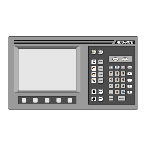
VRO 300T Introduction Keypad Selects absolute or incremental display INCR TOOL Selects radius or diameter display Application-specific function keys System System setup INFO SETUP information parameters and help English / metric conversion Begin a preset Zero an axis ZERO Enter all numeric values... -
Page 11: Display
Introduction VRO 300T Display The 9” CRT display screen is divided into four sections. Status bar – displays the feed rate, current tool, scale factor, the job clock, and inch/mm status. Information screen – displays information for the task being performed. -
Page 12: Readout And Program Displays
VRO 300T Introduction Readout and Program Displays keys switch the display between the digital readout (DRO) display and the program (PGM) display. In the DRO display, all standard readout operations are available. The display can show up to four axis positions simultaneously. If you use more than four, press the softkey to view the other axes. -
Page 13: Power-On Position Recovery
VRO 300T Power-On Position Recovery Position-Trac Certain ACU-RITE encoders, such as the ENC 150, contain closely-spaced reference marks that enable the display to show the correct position after a power interruption. The readout will indicate when power has been lost, and will prompt you to move each axis until a reference mark is located. -
Page 14: Readout Operations
VRO 300T Readout Operations Readout Operations Clear Key Use the key to erase digits that you have entered by mistake or to take CLEAR you back if you’ve pressed an incorrect function key. Absolute and Incremental Displays Absolute Zero, The tool is positioned at also called datum -1.625 ABS. -
Page 15: Radius / Diameter Displays
Readout Operations VRO 300T Radius / Diameter Displays Pressing the key lets you view the part dimension either as a radius or as a diameter. 1.250 0.625... -
Page 16: Zeroing The Displays
VRO 300T Readout Operations Zeroing the Displays 3.00 Absolute Zero 1.75 1.00 On many prints, the dimensions are measured from one or two surfaces of the part. By setting the readout’s absolute display to zero at a well- chosen surface, you can enter the part’s dimensions directly from the print, using absolute presets. - Page 17 Readout Operations VRO 300T Crossfeed Axis Touch the tool to the diameter of the workpiece. 1.25 Make sure that the absolute position is displayed. INCR Press the key for the appropriate axis. ZERO ZERO Enter the tool position—either as a radius or as a diameter, depending on the display.
- Page 18 VRO 300T Readout Operations Setting Absolute Zero with the Tool under Load Longitudinal Axis Make sure that the absolute position is displayed. INCR Machine the face of the workpiece. While the tool is still contacting the workpiece, press the key for the appropriate axis, then the ZERO softkey.
-
Page 19: Incremental Zero
Readout Operations VRO 300T Crossfeed Axis Make sure that the absolute position is displayed. INCR Machine the diameter. While the tool is still contacting the workpiece, press the key for the ZERO appropriate axis, then the softkey. The readout will lock LOCK AXIS this tool position in the display, even if you move the tool. -
Page 20: Presetting
VRO 300T Readout Operations Presetting When you preset a dimension, the readout places an incremental zero at the location you specify. Then, the display automatically switches to the incremental display so you can move to zero. Begin a preset by pressing an axis key ( example). -
Page 21: Absolute And Incremental Presets
• incremental presets for incremental dimensions. When you enter an absolute preset, it does not matter where the tool position is. The VRO 300T calculates the desired location automatically. The display shows this. 3.00 1.75... -
Page 22: Near Zero Warning
VRO 300T Readout Operations Near Zero Warning When you are moving to zero, the readout can “warn” you when you are getting close. This allows you to machine faster and avoid overshooting your desired location. You can set the near zero range in Setup. -
Page 23: Tool Offsetting
Readout Operations VRO 300T Tool Offsetting can store the dimensional offsets for up to 100 tools. When you VRO 300T change a workpiece and establish the absolute zero, all the tools are automatically referenced to the new zero. To select a tool, press the... -
Page 24: Program Operations
VRO 300T Program Operations Program Operations A program is a list of tool changes and position presets that you can save for later use. Creating a Program Press the key, and the program view screen appears. Program Name Axis Position... -
Page 25: Tool Steps
Program Operations VRO 300T Tool Steps Put this step in your program whenever you SET TOOL need to use a different tool. Press the TOOL TOOL key to bring up the Set Tool form. NUMBER —enter the tool number. When you press OFFSET -1.2540... -
Page 26: Position Steps
VRO 300T Program Operations Position Steps This step lets you program a positioning move. You can preset up to four axes at once. The dimension in each axis can be absolute or incremental. —press an axis key to specify which... -
Page 27: Saving And Loading Your Programs
To delete a program which has been saved, press the softkey, move to DELETE the program name, and press again. DELETE The VRO 300T will ask you for confirmation before you clear or delete a program. -
Page 28: Alphabet Entry
VRO 300T Program Operations Alphabet Entry When you need to enter alphabetic characters, press the softkey and ALPHABET the alphabet box appears. ALPHABET A B C D E F G H I J K L M N O P Q R... -
Page 29: Running A Program
Program Operations VRO 300T Running a Program To run a program, move to the first step and press the softkey. You must now execute the step and, when you are done, press the softkey NEXT to run the next step. -
Page 30: Teaching A Position
VRO 300T Program Operations Teaching a Position To teach a position to the readout as you are making a part, select a step as you normally would. In any field where a position is needed, instead of entering numeric position values, machine to the position that you want to enter, then use the softkey to enter the position value. -
Page 31: Other Features
Calculator VRO 300T Other Features Calculator The four-function calculator keys, , are available when you are in any numeric data entry field. Just use these keys as you would any calculator. The keys will act on a number that is already in the field. For example, if you move to a field which already has a value of 3.125, and you want to double it,... - Page 32 VRO 300T Calculator Trig functions are calculated by entering the angle first and then the appropriate trig function. For example, enter , then select the softkey. A value of 0.5000 (sin 30º) will be displayed. Taper Calculator You can calculate tapers either by entering...
- Page 33 Calculator VRO 300T RPM Calculator This feature lets you calculate the correct RPM CALCULATOR rotational speed based on the diameter you DIAMETER are cutting and the desired surface speed. 2.000 INCH —enter the workpiece diameter. You IAMETER SURFACE SPEED can change to metric with the key.
-
Page 34: Printing
VRO 300T Printing Printing If you have a printer connected to the , you can have the readout VRO 300T print various pieces of information. Softkeys are available whenever there is something that you can print. PRINT —when the axis positions are displayed, press the... - Page 35 Printing VRO 300T PRINT TOOL —when you are looking at the tool library, press the softkey IBRARY to print a copy of it. TOOL LIBRARY NUMBER X OFFSET OFFSET 0.5020 0.0021 INCH 0.2953 1.3822 INCH 2.0030 —the softkey is displayed in the Job Setup screen.
-
Page 36: Remote Interface
VRO 300T Remote Interface Remote Interface You can enter commands into the from a remote terminal or VRO 300T computer if you have configured the serial port as a . These remote COMPUTER commands are in the form of ANSI standard ASCII characters. The remote... -
Page 37: Keypad Commands
Remote Interface VRO 300T Keypad Commands Sending one of the control characters from the following table to the readout is equivalent to pressing the corresponding readout key. Control Readout Keypress Control Readout Keypress Character Character ZERO X ZERO Z1 ZERO Z2 ZERO Y . -
Page 38: Job Clock
VRO 300T Other Features Job Clock The job clock can help you Hours : Minutes estimate jobs or monitor throughput. It records to the nearest minute. You can start, stop, and reset the job clock using the softkeys in Setup. -
Page 39: Setup
Setup VRO 300T Setup key lets you change the system parameters. Some of these SETUP parameters are job related, meaning that they may change from job to job. Others are machine related and should be set as part of the installation. The... -
Page 40: Job Setup
VRO 300T Setup Job Setup Setting Up the Tool Library can store the dimensional offsets for up to 100 tools. When you VRO 300T change a workpiece and establish the absolute zero, all the tools are automatically referenced from the new workpiece zero. - Page 41 Setup VRO 300T Longitudinal Axis: Make a face cut. While the tool is still in contact with the workpiece, press the softkey. LOCK AXIS Move the tool away from the workpiece and measure the face location. Enter the measured value.
-
Page 42: Display Resolution
VRO 300T Setup Display Resolution The display resolution will normally be the DISPLAY RESOLUTION same as the encoder resolution. However, if the X AXIS job tolerance is coarser than the encoder 0.0005 resolution (for example, the job tolerance may be ±0.005"), you can adjust the display Z1 AXIS resolution so you won’t be tempted to waste... -
Page 43: Linear Error Compensation
Setup VRO 300T Linear Error Compensation includes a linear error compensation feature that enables you VRO 300T to compensate for machine tool inaccuracies. You can have up to 99 different compensation segments per encoder. In order for linear error compensation to function properly, the readout needs to be able to establish the segment boundaries in the same physical locations each time you turn on the readout. -
Page 44: Anchoring The Segments
VRO 300T Setup Anchoring the Segments If you anchor the beginning of the first segment at a known location on the encoder, then the segment boundary values will be the actual physical distances from the anchor point, as shown below. -
Page 45: Compensation Entry Methods
Setup VRO 300T Compensation Entry Methods You can enter the segment boundaries and compensation factors using the keypad, or you can have the readout calculate them for you. Normally, you would use the keypad entry method only to restore or adjust a known compensation value. - Page 46 VRO 300T Setup Calculated Entry This brings up the softkeys needed to have the readout calculate CALCULATE the compensation factors. COMP CLEAR ANCHOR CANCEL DONE SEGMENT TABLE SEGMENT 1 softkey brings up the CALCULATE SEGMENT form. SEGMENT —This is where you enter the actual...
- Page 47 Setup VRO 300T You will need a dial indicator and a measurement standard. Position the standard in the center of the segment. Enter one edge of the standard. FIRST POINT Enter the other edge of the standard. SECOND POINT Enter the actual size of the standard, including the probe diameter if necessary.
-
Page 48: Feed Rate Units
VRO 300T Setup Feed Rate Units Use the softkeys to change the feed rate units between MMPM inches per minute and mm per minute. Remote Switch The external switch (pendant or footswitch) REMOTE SWITCH can be enabled to perform any or all of the... -
Page 49: Vectoring
Setup VRO 300T Vectoring Vectoring breaks down the movement of the DIA 2 DIA 1 compound axis into the crossfeed or longitudinal axes. If you are turning threads, for example, vectoring lets you see the diameter of the thread in the X-axis display, even though you are moving the cutting tool with the compound axis handwheel. -
Page 50: Scale Factor
VRO 300T Setup Scale Factor The scale factor can be set to scale the workpiece up or down from the preset or programmed size. All preset and displayed dimensions are multiplied by this scale factor. All programmed dimensions will be multiplied by this scale factor when the program is run. -
Page 51: Installation Setup
Setup VRO 300T Installation Setup Display Configuration Individual encoders are connected to the at inputs numbered 1 VRO 300T through 6. The assignment of each encoder to an axis display (X, Z1, or Y for example) is done by completing this form. -
Page 52: Encoder Setup
VRO 300T Setup Encoder Setup You must tell the readout something about the encoders. Select ENCODER from the Installation Setup list and enter the encoder number (the SETUP number is defined by the input connector number on the back panel of the readout). -
Page 53: Serial Port
Setup VRO 300T Serial Port You can configure the serial port to connect to a printer or to a computer. Check the specifications for your printer or computer to determine how to complete the following information. For most items, the softkeys will provide you with the SERIAL PORT available choices. -
Page 54: Parallel Port
VRO 300T Setup Parallel Port Most printers connect to the parallel port. You can experiment with these settings to format the printed output. PARALLEL PORT —select to disable the port or UNCTION PORT CONFIGURATION FUNCTION PRINTER to enable it for printing. -
Page 55: Installation
40°C (32° to 104°F) with a non-condensing relative humidity of 25% to 85%. Proper Mounting ACU-RITE has developed special mounting kits for the readout which address the most common mounting requirements. Mounting kits include: • Column and base machine mountings •... - Page 56 VRO 300T Installation Connecting the Encoders Insert the connector from each encoder into the mating connector on the back of the readout. Fasten it with a small screwdriver. Provide enough slack in the encoder cables to allow for full travel of all machine axes.
-
Page 57: Readout Specifications
Reference signal: TTL square wave Control Function Compatible with ACU-RITE CFI box Interface (CFI) Edge finder input Compatible with ACU-RITE electronic edge finder Touch probe input Compatible with Heidenhain touch probe Ext. video output VGA 640 x 480 pixels Pendant input... -
Page 58: Troubleshooting
This section is intended to provide you with some basic troubleshooting assistance with your readout system. If you cannot correct the problem after following these instructions, contact your authorized ACU-RITE distributor or OEM/OEI for repair or replacement procedures. No Operation... - Page 59 Troubleshooting VRO 300T • Check fuse. With the power cord removed, use a thin straight-blade screwdriver to remove the cover of the electrical input module. Slide out the fuse holder and check the fuse. If necessary, replace it. Replace the input module cover by snapping it back into place, and reconnect the power cord.
- Page 60 VRO 300T Troubleshooting If the system seems to be displaying incorrect positions, check the following items. • Verify presets. Make sure that the numbers you entered are correct. • Verify tool. Check that the correct tool number is being used. Make sure the correct tool offset has been entered.
- Page 61 ACU-RITE Readout Systems are manufactured in the USA SALES & SERVICE: A Tech Authority, Inc. 13745 Stockton Ave. ACU-RITE IS AN ISO 9001 Chino CA 91710 909-614-4522 CERTIFIED sales@atechauthority.com MANUFACTURER ACU-RITE INCORPORATED ONE PRECISION WAY MASON INDUSTRIAL PARK JAMESTOWN, NEW YORK 14701...
Need help?
Do you have a question about the VRO 300T and is the answer not in the manual?
Questions and answers