
Subscribe to Our Youtube Channel
Related Manuals for Dexter Laundry T-450 C4


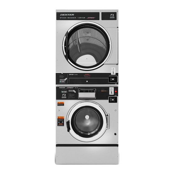
Summary of Contents for Dexter Laundry T-450 C4
- Page 1 USE THE BLUE TABS LOCATED ON THE RIGHT AND LEFT SIDES OF THE FOLLOWING DOCUMENT TO ADVANCE TO EACH SECTION. 8533-119-001 3/22...
- Page 2 Dexter Commercial Vended Stack Washer Dryer Caution! To reduce the risk of damage to the Water Inlet T-450 C4 Valve, do not supply inlet water with a temperature that exceeds 70˚ C. Parts & Service Manual...
- Page 3 Equipment Safety Warnings Indicates an imminently hazardous situation, Symbols and Terminology Used in this Equipment which if not avoided, will result in death or seri- ous injury. Indicates a potentially hazardous situation, Warning! Do not operate equipment if door glass is which if not avoided could result in death or damaged in any way.
- Page 4 WARNING WARNING •All washers must be installed in accordance to all Children should be supervised to applicable electrical, plumbing and all other local ensure they do not operate or play codes. in or around equipment. •These installation and operation instructions are for use by qualified personnel only.
- Page 5 Prohibited! Do not attempt to open, touch, or pro- Warning! Do not operate equipment if door glass is ceed before referring to the manual or unless quali- damaged in any way. fied. Mandatory! Read all supporting documentation be- fore operating or maintaining equipment. Warning! Keep clear of rotating parts.
-
Page 6: Table Of Contents
Dexter Safety Table of Contents Drain Valve Access ........118 Section 8: Guidelines Section 1: Drain Valve Cleaning ........118 Washer Electrical & Wiring Schematics Specifications, Mounting Dimensions Detergent Dispenser ........120 Start Circuit ..........146 Specifications..........15-16 Vacuum Breaker/Air Gap .......120 Fill Circuit ..........146-147 Dimensions.............17-18 WARNING... - Page 7 Stacked Washer Dryer Models Stacked Model Washer \ Dryer Electrical Specs. Designation Model # SC0450NE-17EC4X- DCS030ND-15EC2X- 120 or 208-240/60/1, Single 2 Wire + Ground, SWBCG-USA United States Quarter Optical Acceptor SWBCG-USA WCS450XC-12EC4X- 208-240/60/1or3, Single 2 Wire + Ground, 3 SWBCS-USA Phase 3 Wire + Ground, United States Quarter 9999-744-001 Optical Acceptor...
- Page 8 Stacked Washer Dryer Models Stacked Washer Dryer Models Stacked Model Washer \ Dryer Stacked Model Washer \ Dryer Electrical Specs Electrical Specs. Designation Model # Designation Model # SC0450NE-39AC4X- DCS030ND-39AC2X- 230/50/1, Single 2 Wire + Ground, No acceptor SC0450NE-39AC4X- DCS030ND-39AC2X- 230/50/1, Single 2 Wire + Ground, No acceptor SWKSG-VRX SWKMG-THX...
-
Page 9: Specifications
SPECIFICATIONS Washer Specifications: 30 lb. Commercial Dryer: T-30 SWD DCS030N_-15EC_X (60Hz), DCS030N_-39AC_X (50Hz) Cabinet Height (As a stand-alone dryer) 38 7/8” 987 mm. Dry Weight Capacity 30 lbs (13.6 kg) (Assumes minimum leveling leg adjustment) Cylinder Diameter 25” (63.5 cm) Cabinet Height (Combo washer/dryer) 78 3/4”... -
Page 10: Machine Dimensions
Machine Dimensions: SWD Mounting Pad Dimensions Part # 8533-119-001 3/22 Part # 8533-119-001 3/22... -
Page 11: Washer Installation
Washer Installation All washers must be installed in accordance with all local, state and national building, electrical, and plumbing codes in effect in the area. Foundation Requirements The washer must be securely bolted to a substantial concrete floor, or mounted upon a suitable base which is securely bolted and machine grouted to a substantial concrete floor. -
Page 12: Dryer Installation
Dryer Installation To Make Electrical Connections All commercial dryer installations must conform with local applicable local codes or in the absence of lo- Disconnect all power to the washer. Remove screw and lift out the cover located in the upper left corner cal codes, with the National Fuel Gas Code ANSI Z223.1A-1988. - Page 13 recommended that no more than 14 feet of straight 6” diameter pipe with two right angle elbows be used. NOTE: The following considerations must be observed for gas dryer installations where When more than two elbows are used, two feet of straight pipe should be removed for each additional dry cleaners are installed.
-
Page 14: Washer Operating Instructions
Washer Operating Instructions At the correct time in the wash bath cycle the “ADD BLEACH” Detergent will come on indicating the time and showing a diagram of Measurements Washer Emergency Stop / Safety Door Lock the location for adding bleach if desired. The timing is 2 1/2 minutes after start of wash bath the light will come on and This machine is equipped with a Safety Door Lock that locks the door closed from when the cycle is stay on for 2 1/2 minutes or end of wash bath . - Page 15 TRANSIENT VOLTAGE SURGE SUPPRESSORS Notes Like most electrical equipment your new machine can be damaged or have its life shortened by voltage surges due to lightning strikes which are not covered by factory warranty. Local power distribution problems also can be detrimental to the life of electrical components. We recommend the installation of transient voltage surge suppressors for your new equipment.
-
Page 16: Washer And Dryer Programming Instructions
PROGRAMMING INSTRUCTIONS: The washer control can be programmed to prompt the user for alternate vend prices, change washer cycle times, temperatures, and many other options. This can be accomplished in two ways: 1. Manual programming utilizing the “START”, “HOT”, “WARM”, and “COLD” buttons 2. -
Page 17: Rapid Advance Mode
Programing Selection: Optional Cycles Option: These alternate functions allow the user to move through a menu of options to choose various program- mable settings. Figure 2, shown below, shows the top level menu. Choosing an option from the top level This option allows the user to select the different test and short-cycle options. - Page 18 Prices Option: Final Rinse and Spin Option: This option allows the user to set values for coin acceptor inputs and to set the vend price. It also allows “Final Rinse and Spin” will begin only the Final Rinse Bath and Final Spin portions of the cycle without the the user to return the values to factory defaults.
- Page 19 Temp Pricing Option: Cycles Option: The Temperature Pricing option allows for the user to prompt the customer for varying vend prices based This option allows the user to set the bath time and spin time for the “Wash” bath. It also allows the user on the water temperature the customer selects.
-
Page 20: Default Temp
Final Spin: Plus Cycle Options: The washer “Final Spin” is the spin that occurs after all selected baths & intermediate spins have been The Plus Cycle options allow for the user to prompt the customer for varying vend prices based on addi- completed. -
Page 21: Settings Options
Pre-Wash: Settings Options: If the user programs a “CYCLE TIME” for Pre-Wash other then 0 (“NO CYCLE”), the feature becomes ac- The Settings options allow for the user to make various programming changes to change how the control tive. However, the customer will not be prompted to pay an additional vend price for Pre-Wash unless the operation affects the customer. - Page 22 Date: Sounds: The control uses a Real Time Clock (RTC) to internally track the time and date. The RTC continues opera- If the user programs the Sounds to “OFF”, the control will not sound the enunciator at the end of a wash tion even if the control loses external power.
- Page 23 Control Menu: Coin Audit: The Control menu allows for the user to observe important technical information for the control and Vari- able Frequency Drive system. No changes can be made at this menu. See below for detailed information The coin audit field shows the accumulation of coin pulses that were sent to the control over each of the on each sub menu.
-
Page 24: Dryer Programming
USB Menu: PROGRAMMING THE DRYER CONTROL The USB menu allows for the user to move programming files back and forth from a common USB memory The dryer control can be programmed to prompt the user for alternate vend prices, change dryer cycle stick. - Page 25 These alternate functions allow the user to move through a menu of options to choose various program- When manual programming mode is entered, the “START”, “HIGH”, “MEDIUM”, and “LOW” buttons per- mable settings. The figure below shows the top level menu. Choosing an option from the top level menu form alternate functions.
- Page 26 Continuous Test Option: Prices Option: Similar to the Quick Test, when the Continuous Test Option is chosen, the dryer will begin a dry cycle This option allows the user to set values for coin acceptor inputs, vend price and time and extend dry price without the displayed vend price being met.
- Page 27 Cycles Option: The figure below shows the sub menu options for Prices: This option allows the user to set temperature and cooldown information for the drying cycle. It also al- lows the user to return the values to factory defaults. 1.
- Page 28 Temperature Pricing Option: This option allows the user to require additional vend amounts be added based on the drying temperature chosen by the customer. This pricing adder is effective only for the Base Vend Price (it does not affect the NO HEAT –...
- Page 29 Settings Options: 8. “SHIFT HOURS”: This feature allows the user to shift the time used by the control from the time The Settings options allow for the user to make various programming changes to change how the control kept internally by the control. The control uses a Real Time Clock (RTC) to internally track operation affects the customer.
- Page 30 Usage Menu: The figure below shows the sub menu options for Settings: The Usage menu allows for the user to track data about machine usage. See below for detailed informa- tion on each sub menu option. 1. “COIN AUDIT”: The coin audit field shows the accumulation of coin pulses that were sent to the control over each of the left and right coin inputs.
- Page 31 Control Menu: The Control menu allows for the user to observe important technical information for the control. No changes can be made at this menu. See below for detailed information on each sub menu. 1. “SERIAL NUMBER”: This is the control serial number. 2.
- Page 32 Notes Part # 8533-119-001 3/22 Part # 8533-119-001 3/22...
-
Page 33: Dryer Service,Troubleshooting And Schematics
Service Procedures Clothes Door Removal 1. The clothes door may be removed from the hinge bracket by unscrewing and removing the allen- head pivot screw located at the door upper hinge point. 2. Next lean the door out of the top of the hinge bracket and lift the door from the bottom hinge pin. - Page 34 B. Manual Reset Over temperature Safety Thermostat- The second hi-limit Temperature Testing thermostat is located on the right side of the burner housing as you view from the back of the To check the temperature in the dryer tumbler, press and hold the start button and while holding the start machine.
- Page 35 Air Flow Switch Operation And Adjustment Ignition System-Function & Sequence During normal dryer operation, the following occurs: The air flow switch assembly is part of the ignition safety circuit and insures that the burners don’t operate unless there is air flow. When the drive motor and blower are running the flat actuator is pulled in against 1.
-
Page 36: Cylinder Removal
Main Burner Orifice Removal Notes 1. Remove manifold and gas valve assembly as above. 2. Using an open end wrench, remove orifices from manifold. Main Burner Removal Remove the 4 screws securing the cover for the burner housing and the one screw mounting the high limit cover. -
Page 37: Trouble Shooting Dryer
Trouble Shooting Dryer Electronic Control Diagnostic Lights The electronic control has 3 diagnostic lights to aid in service of the dryer. The Dryer has indicator lights for the motor circuit, door switch circuit, and the heat circuit. When the electronic control is carefully unlocked and moved forward these lights are visible on the circuit board. -
Page 38: Error Codes
Error Codes To enter a test Cycle Mode you will have to enter the programing mode: Symptom Probable Cause Suggested Remedy MANUAL PROGRAMMING: The dryer must be in idle mode for the manual programming menu to be accessed. Idle mode is when the PCB ERROR2 Analog / Digital Error Power machine down and try to reset... -
Page 39: Troubleshooting
TROUBLESHOOTING Probable Suggested Symptom Suggested Remedy Symptom Probable Cause Cause Remedy Tumbler turns Glass Fuse Check small glass control fuse in back of dryer. but no spark Replace if failed. Tumbler does not turn Drive Belts Check both drive belts. at burner Replace if failed. -
Page 40: End Of Cycle
60HZ Wiring Schematic Dryer Idle - No Coins Added Top Dryer Used For This Example Manual Reset Safety Shutoff Over-Temperature Thermostat Top Dryer Used For This Example 110 VAC 60Hz is supplied to the main power terminal block, L1 power, N=neutral, plus ground. BLK/Red coming off of L1 and BLK/BLU coming from N power the R1, and R2 motor relays. - Page 41 Wiring Schematic Dryer 60Hz Notes Part # 8533-119-001 3/22 Part # 8533-119-001 3/22...
- Page 42 Wiring Diagram Dryer 60Hz Notes Part # 8533-119-001 3/22 Part # 8533-119-001 3/22...
-
Page 43: Dryer Parts Data
Kits, Assemblies, & Common Parts Description Part Number SWD Makeup Air Kit 9732-333-001 Cleanout Duct Assembly 8” 9973-034-001 Temperature Probe 9501-010-001 Controls Blue 9857-199-002 Controls Black 9857-199-004 Coin Drop 9021-094-001 Optical Switch 9801-099-001 Coin Drop Screws 9545-053-002 Ignition Control Box 9857-182-001 Electrode Assembly 9875-002-003... - Page 44 Dryer Cabinet Group Cabinet Group 2, 3 Description T-30 SWD Panel Assy., Front- Upper (SS) 9989-602-001 Insulation Front Panel, half moon (top) 9277-063-001 Insulation Front Panel, half moon (bottom) 9277-063-002 Screw, FLHDCR, 10B x 1 9545-008-014 Washer, Finish, #10 8641-585-001 Nut, Spring 8640-442-001 Hinge ,Backup Plate...
- Page 45 Cabinet Group Continued Dryer Cabinet Group Key Description T-30 SWD Escutcheon, SWD, Dryer Coin 9994-041-001 Trim, Overlay Blue 9435-055-002 Trim, Overlay Black 9435-055-001 Screw, #4-40 x 3/16 9545-020-009 Nameplate Stack Dryer Express Blue 9412-202-002 Nameplate Stack Dryer Express Black 9412-202-001 Lint Drawer Assembly Blue 9866-004-001 Lint Drawer Assembly Black...
- Page 46 Dryer Modular Cabinet Group Dryer Back Panels and Guards (After Serial D1.23283.027) Description T-30 SWD Cabinet Base Assembly 9945-169-002 Back Panel Assembly 9989-739-002 RH Side Panel Assembly 9444-121-003 LH Side Panel Assembly 9444-121-004 RH Lint Rail Guide Assembly 9750-025-001 LH Lint Rail Guide Assembly 9750-026-001 Lower Baffle Brace 9046-106-001...
- Page 47 Air Flow Switch Assembly Dryer Burner Housing Group Key Description T-30 SWD Housing Assembly, Burner (All sheet metal parts not 9803-241-001 listed) Service Burner Plate Front 9454-991-001 Screw, 10B X 1/4” 9545-008-001 Service Plate baffle Recirculation Chamber Clean Out 9452-850-001 Screw, 10B x 3/8”...
- Page 48 Bearing Housing Group Key Description T-30 SWD Bearing Housing Complete Assy (Includes bearings 9803-160-003 & Spacer) Housing, Bearing 9241-161-002 Spacer, Bearing 9538-139-002 Bearing, Ball, Front & Rear 9036-130-001 Screw-Wizlock, 3/8-24x3/4 9545-049-002 Nut, 3/8-24 8640-400-002 Screw, 3/8-24x1 9545-049-001 Nut, 3/8-24 8640-415-002 Part # 8533-119-001 3/22 Part # 8533-119-001 3/22...
- Page 49 Tumbler Group Description T-30 SWD Key Description T-30 SWD Wire Harness Overtemperature Switch 9627-861-001 Tumbler Assy Complete W/Spider (GALV) 9848-147-001 Switch Assy, Air Flow 9801-095-001 Tumbler Assy (Galvanized) 9848-146-001 Switch, Air Flow 9539-461-009 Tumbler Assy Complete W/Spider (SS & Galv 9848-147-002 Bracket, Switch- Air Flow 9029-174-001...
- Page 50 Rear View Photos Description T-30 SWD Arm Assy-Tension, Complete 9861-022-001 Washer, Flat 8641-581-035 Ring-Retaining 9487-200-003 Pulley Assy, Intermediate with bronze flange bear- 9908-039-004 Bearing - Bronze Flange 9036-145-002 Spacer-Shaft (See Tumbler Group for Expanded 9538-164-002 View) Tolerance Ring 9487-234-005 Pulley, Driven 9908-049-002 Washer -Flat 8641-581-026...
- Page 51 Control Assembly Group Rear View Photos 6, 7 Part # 8533-119-001 3/22 Part # 8533-119-001 3/22...
- Page 52 Control Assembly Group Door Switch Group Key Description T-30 SWD Key Description T-30 SWD Door Switches 9539-487-001 Control, Rear 9857-233-001 Bracket-Mounting lint tray switch 9029-303-001 Bracket, Terminal Block Power 9029-202-001 Conduit-Wire 6068-051-001 Strip, Terminal Marker 9558-029-003 Grommet Wire 1/2 i.d. 9029-089-001 Terminal-Block, Power, 4 Pole 9897-035-001...
- Page 53 Coin Handling Group Notes Description Part Number Coin Acceptor, Optical, SWD, US Quarter 9021-094-001 Harness-Extention ,Control to Acceptor, Optical Dryer 9627-916-002 Retainer, Coin Acceptor 9486-145-001 Screw, Torx 9545-053-002 Switch Assembly, Optical Sensor, SWD 9801-099-003 Screw-Height Bar, 3mm 9545-039-002 Below not included Harness, Acceptor Mechanical (Control to Acceptor) 9627-783-003 Coin Vault...
- Page 54 Wiring Diagram 60Hz Coin Handling Group Electronic Description Part Number Kit, Electronic Coin Acceptor 9732-303-004 Acceptor-Electronic, US/CA 9021-054-001 Harness, Control to Acceptor, Dryer 9627-909-003 Harness, Control to Acceptor, Washer 9627-909-002 Lable-Wiring, Electronic Acceptor 8502-730-001 Retainer Coin Acceptor, Electronic 9486-155-001 Screw, 4B x 5/8 ss, Torx T-10 9545-053-002 Below not included Harness, Adaptor Electronic to Mechanical switch...
- Page 55 Wiring Schematic 60Hz Notes Part # 8533-119-001 3/22 Part # 8533-119-001 3/22...
-
Page 56: 50Hz Gas Dryers
-39 T-30 SWD 50 Hz Parts Description Part Number Strip, Terminal Marker -39 Models 9558-029-004 Transformer 8711-007-002 Instructions, Transformer Connect 8507-230-003 Ignition Control -39 Models 9857-182-001 Harness-Ignition Control, 9627-867-011 Wire Assembly High Voltage 9631-403-009 Motor 9376-318-002 Pulley, Motor Drive 9453-169-009 Harness Motor Extension 9627-864-007 Wiring Label Schematic/Diagram -39 models... - Page 57 Rear View Photos T-30 SWD -39 Gas Control Parts Description Part Number Kit-Honeywell VR86 Valve Flange 9732-162-001 Orifice, Main Burner #32 9425-069-009 Gas Control Valve 9857-132-004 Part # 8533-119-001 3/22 Part # 8533-119-001 3/22...
- Page 58 Wiring Diagram for Dryer 50hz 230V -39 Coin Handling Group Electronic Description Part Number Kit, Electronic Coin Acceptor 9732-303-004 Acceptor-Electronic, 9021-054-001 Harness, Control to Acceptor, Dryer (w/o lint door switch) 9627-909-003 Harness, Control to Acceptor, Dryer (with lint door switch) 9627-909-005 Harness, Control to Acceptor, Washer 9627-909-002...
- Page 59 Wiring Schematic for Dryer 50hz 230V -39 -59 Models 50 Hz Parts Part Number Description Quantity 9558-029-004 Strip, Terminal Marker (Before Serial) ........ 1 9558-033-001 Strip, Terminal Marker (After Serial) ........1 9183-030-001 Filter EMI ................ 1 8711-008-002 Transformer (Before Serial) ..........1 8711-004-004 Transformer (After Serial #) ..........
- Page 60 Wiring Diagram for Dryer 50hz -59 Notes Part # 8533-119-001 3/22 Part # 8533-119-001 3/22...
-
Page 61: Washer Service And Troubleshooting
Electronic Acceptor Coin Drop (Original Design) Setting the electronic coin acceptor switches Some washer models come equipped with an electronic coin acceptor. Follow the instructions below for setting the switches for the desired country and currencies. 1. The electronic coin acceptor has switch settings depending on the coins and country. See the table below for available values of the left and right coin inputs for the available countries. - Page 62 Maintenance Instructions -Electronic Acceptor (Original Design) Maintenance Instructions -Electronic Acceptor (Original Design) 1. Instructions to open the flap of the coin selector CENTER OF ROTATION Rotate the spring clockwise for about 40 to 60 degrees until it becomes free of the protrusion. Lift off the spring with the attached plastic part.
- Page 63 Maintenance Instructions -Electronic Acceptor (Original Design) Maintenance Instructions -Electronic Acceptor (Original Design) 4. Close the coin selector 6. Adding the bolt #4036 A bolt can be added to the EMP 500 v4 to reduce attempts of vandalism or to protect the unit from improper use. To shut the coin selector follow pictures 1 to 3 in NOTE: that some front plates/cashboxes might not allow mounting this additional device.
-
Page 64: Front Panel Removal
Optical Acceptor Front Soap Box removal Step 1: Remove front Panel Step 2: Remove the six 3/8 nuts and remove Soap Standard Coin Drop Acceptor Box mounting bracket and Soap Box, The drop style coin acceptor contains a optical switch that is sensed by each good coin that is accepted. followed by removing gasket. -
Page 65: Detergent Dispenser
Detergent Dispenser The detergent dispenser is located at the top of the front panel. It is fed water from the vacuum breaker assembly at the rear of the machine to flush the soap with hot water during the wash bath and the fabric ... -
Page 66: Adjusting The Loading Door
Adjusting the Loading Door Door cam Flat blade screw on check position The door can be adjusted by changing the number of shims behind the door hinge and the door lock door switch latching assembly. The vertical fit of the door to the tub can be altered by loosening the door hinge bolts and raising or lowering the door before retightening. -
Page 67: Loading Door Reassembly
Loading Door Reassembly Tub Back, Bearing, and Cylinder Assembly Step 1: Lay the door ring face down on a flat surface. Start the glass into one side of the door gasket. Step 2: Use one hand underneath to push the gasket out and the other hand on the top pulling the gasket in place. -
Page 68: Bolt Torque Chart
Basket Pulley, Bearing Housing, Water Seals, and Tub Back Reassembly Step 1: When installing new bearings into a bearing housing, first press the The cast iron basket pulley is retained by a bolt, locking washer, and a flat washer. front (large) bearing into the housing until it bottoms. With the bearing spacer in place, press the rear bearing in until the spacer is snug between the two bearings. -
Page 69: Control Mounting Trough
Control Mounting Trough Emergency Stop Button Switch Assembly Remove rear panel to access control trough. It sets on the right side of the machine and holds the control The stop button is mounted on right side of machine. Remove the top and access the rear of button. PCB’s, transformers,and pressure switch. -
Page 70: Switch Positions
Switch Positions: Electronic Pressure Sensor Depth (in): Pos 1 Pos 2 Pos 3 Pos 4 Pos 5 Pos 6 The Electronic Pressure Sensor comes standard on all models Starting September, 1st 2015. Machines 5.00 manufactured before this date can be upgraded with Kit 9732-314-001. The Pressure sensor is adjustable. 5.25 The Factory settings chart will let you know the starting values for each machine and by following the 5.50... -
Page 71: Delta Variable Frequency Drive
Common Washer Troubleshooting Solutions Symptom Probable Cause Suggested Remedy Machine Power Supply Check these areas: Circuit breakers, Voltage, Power leads, does not Power connections. Is front display LED showing a dollar start amount. Delta Variable Frequency Drive: Door Switch Check for continuity through door switch when door is Main power is connected to terminals L1, L2, and L3 on the Delta drive. - Page 72 Common Washer Troubleshooting Solutions Symptom Probable Cause Suggested Remedy Symptom Probable Cause Suggested Remedy Door will not Door Rod Check to see that door rod from gear motor to lock assemble is open long enough to allow lock assemble to disengage. If not, adjust Water does Pressure Switch Check pressure switch continuity between terminals.
- Page 73 Troubleshooting Machine Fault Errors Displayed on front of washer Fault Description Customer Action COMM I2C Bus Error Condition Washer controller communication error on the I2C The following pages are a description of fault codes that will appear on the front of the ERROR 1 bus.
- Page 74 Troubleshooting Machine Fault Errors Fault Description Customer Action Fault Description Customer Action COMM VFD Non Condition This error is when the washer controller cannot COMM Communication Condition If a state-of-health message reply is not seen by the ERROR 4 Existent Or communicate with the drive.
- Page 75 Troubleshooting Machine Fault Errors Troubleshooting Machine Fault Errors Fault Description Customer Action Fault Description Customer Action SLOW Drain Error Condition This error is when an empty water level is not DRAIN reach within 7 minutes. DRIVE VFD Over-Current Condition This error is an over-current on the VF drive ERROR Fault Delay...
- Page 76 Troubleshooting Machine Fault Errors Troubleshooting Machine Fault Errors Fault Description Customer Action Fault Description Customer Action INVALID Drive Is Not Condition The error indicates the VF drive is not a Dexter DRIVE Condition This error is over-heating on the VF drive DRIVE The Correct version of the Delta E-drive.
- Page 77 Troubleshooting Machine Fault Errors Notes Fault Description Customer Action CRC ERROR Firmware Condition This error occurs the washer control firmware corrupted fails a CRC check. Delay None Action When detected, the dryer control shall not be operational. Solution The error is fatal. The control must be replaced. Part # 8533-119-001 3/22 Part # 8533-119-001 3/22...
-
Page 78: Start Circuit
Electrical Path Circuit Schematics Start Circuit Power travels into the machine on L1, L2, (L3, if 3 phase used). L1 and L2 provide 208- 240VAC to the controls transformer which steps the voltage down to 24VAC for the controls. (The L1 connection at the controls transformer must be checked at start-up to coincide with machine operating voltage) The 24VAC travels out from the transformer on X-1 black/red wire to terminal and then through the red wire to the 7 amp circuit breaker. -
Page 79: Wash Circuit
Unlock Thermoactuator and Shake Out Circuit The prewash or wash LED will illuminate at this time, powered through the white wires from the P-3 connection of the main control PCB to the LED printed circuit board. Using the factory preset cycle as an example: The 70 seconds before the end of the cycle the main control PCB signals the relay PCB to remove 24VAC from washer fills the tub through the back of the machine with either one or both the C1 cold and H1 hot water the orange/blue wire at the P-17 connector on the lock thermoactuator. - Page 80 Wiring Schematic Washer 60 Hz Notes Part # 8533-119-001 3/22 Part # 8533-119-001 3/22...
- Page 81 Wiring Diagram Washer 60 Hz Kits, Assemblies, & Common Parts Description Part Number Kit - Door Lock Assy. & Cam, replaces 9885-024-001 9732-347-001 Kit - Door cam replacement 9732-346-002 Kit - Locking Pawl replacement 9732-346-001 Kit - 8650-012-003 Lock with spacer 9732-344-001 Kit - 3"...
- Page 82 SWD C-Series Accessories T-450 Description Part Number Hose, Water Supply 3/8” I.D. 9990-027-011 Washer, Inlet Hose (furnished) 8641-242-000 Strainer, Inlet Hose (furnished) 9565-003-001 Sealing compound 8538-151-002 TORX#20 Driver 8545-051-002 Special Tool For Removing Coin Acceptor Mounting Screws. (T-10 Torx) 8545-051-003 Flow Restrictors (in dispenser ) 9475-002-003 Battery 3V Lithium (used on Control PCB)
- Page 83 WCS450XA Rear View Access Parts Group Description Part Number Drive Motor, 3 Phase (Inverter duty) 9376-319-001 Rod, Motor Mtg 9497-222-006 Motor Bushing (Rubber) 9053-082-001 Clamp-Worm, 316SS, 1.5" (for Rubber bushing) 8654-117-019 Strap Bracket, Motor Tension 9029-206-002 Nut, Strap to Motor 8640-413-002 Washer 8641-581-006...
- Page 84 13 14 Part # 8533-119-001 3/22 Part # 8533-119-001 3/22...
-
Page 85: Cabinet And Front Panel Group
WSC450XA Cabinet and Front Panel Group WSC450XA Cylinder, Seals & Bearings Description Part Number Description Part Number Panel, Right Side-Painted 9989-604-002 Panel, Left Side - Painted 9989-605-002 Bearings and Seal Kit 9732-219-005 Screw 9545-018-023 Housing, Bearing- Assembly (items #2-#6) 9803-186-001 Panel Assy, Front 9989-606-001 Housing, Bearing... - Page 86 Door Latching Assembly (continued) Description Part Number Lock Assy, Complete (#1-22)(includes #1 thru #22) 9885-024-001 Plate Assy, Door Lock 9982-346-001 Washer, Flat 8641-581-030 Actuator, Latching Switch 9008-005-001 Pawl, Locking 9732-346-002 Washer, Spring 8641-569-003 11 G Ring, Retaining 9487-200-004 Bracket Switch 9029-163-001 Nut, Hex 10-32 UNF 8640-413-002...
- Page 87 Gear Motor Door Lock Assembly Description T-450 Actuator Assembly (Includes 1-10, Rod NOT included) 9892-017-002 Bracket Assy, Slide Lock Actuator 9985-199-001 Bracket Assy, Slide - Unlock 9985-196-001 Bracket Slide Lock 9029-278-001 Spacer, Plastic 9538-157-021 Arm - Door Lock 9001-063-001 Thermoactuator - Door Lock Relay 24VAC 9586-001-003 Spring - Extension 9534-350-001...
- Page 88 WCS450XA Loading Door Group Part # Water Inlet Valve Breakdown Description Part Number Loading Door, Complete #1-10 9960-309-001 Loading Door, Ring (180 Degrees) 9487-265-002 Gasket, Loading Door 9206-419-001 Window, Loading Door 9635-016-001 Shaft Assy, Locking (includes 4 thru 7) 9913-134-003 Shaft, Door Locking 9537-195-002 Cam, Locking...
- Page 89 Drain Valve Group Part # by Model WCS450XA Chassis and Drain by Part # Key Description Part Number Description Part Number Valve, Drain (includes #2 thru #11 9379-202-002 Body, Valve (w/ball) 9064-072-001 Base Assy,Frame 9945-150-002 Outer Tub Assy 9930-166-001 Motor & Gear Train (complete) 9914-137-022 Plate, Motor Mtg 9452-538-001...
-
Page 90: Electrical Components
Electrical Components, Control Trough Description Part Number Trough Assy,Controls 208-240 volt 9857-235-001 Trough only 9839-018-001 Transformer, Control (208/230/60 Hz In 24 VAC Out Volts) 8711-004-004 Wire Assembly, Red 28" 8220-062-025 Screw, #10B x 1/2 9545-008-026 Lockwasher Exttooth #10 8641-582-006 Wire Assembly, BLK/BLU 8220-001-231 9 10 Wire Assembly, BLK/RED... - Page 91 Electrical Components, Upper Channel Front Panel Control Group Part # Description Part Number Description Part Number Nameplate,Control Panel Blue (one piece) 9412-205-002 Terminal Block Assy, POWER 9897-033-002 Nameplate,Control Panel Black(one piece) 9412-205-001 Screw, Mtg 6ABx3/4” 9495-031-010 PCB assembly Control /Display 9473-010-001 Strip, Terminal Marker 9558-025-001...
-
Page 92: Labels
Labels and Diagrams by Part # Coin Handling Group Description Part Number Description Part Number Wiring Diagram, Coin 9506-827-001 Coin Acceptor, Optical, SWD, US Quarter 9021-094-001 Label High Voltage Warning 8502-614-004 Harness-Extention ,Control to Acceptor, Optical Dryer 9627-916-001 Cover controls 9074-267-001 Retainer, Coin Acceptor 9486-145-001... - Page 93 Wiring Schematic for 60hz Coin Washer Coin Handling Group Electronic Description Part Number Kit, Electronic Coin Acceptor 9732-303-004 Accecptor-Electronic, US/CA 9021-054-001 Harness, Control to Acceptor, Dryer 9627-909-003 Harness, Control to Acceptor, Washer 9627-909-002 Lable-Wiring, Electronic Acceptor 8502-730-001 Retainer Coin Acceptor, Electronic 9486-155-001 Screw, 4B x 5/8 ss, Torx T-10 9545-053-002...
- Page 94 Wiring Diagram for 60hz Coin Washer Notes Part # 8533-119-001 3/22 Part # 8533-119-001 3/22...
-
Page 95: 50Hz Washer
Coin Handling Part Description Wiringlabel-Diagram/Schematic -39 9506-829-001 Wiringlabel-Diagram/Schematic -12 9506-827-001 Elect. Acceptor for C series SWD, Malaysia, Singapore, Thailand 9732-303-001 Elect. Acceptor for C series SWD, Swiss, Euro 9732-303-002 Elect. Acceptor for C series SWD, Chile, Mexico 9732-303-003 Elect. Acceptor for C series SWD, US, CAN 9732-303-004 Elect. - Page 96 Wiring Diagram for 50hz Washer -39 Notes Part # 8533-119-001 3/22 Part # 8533-119-001 3/22...
- Page 97 Wiring Schematic for 50hz Washer -39 CE Parts Group (-59) After Serial # Description T-450 Controls Assembly - Trough, 9839-018-001 Circuit Breaker 5198-211-002 Instructions, Transformer Connect 8507-449-004 Controls Transformer 8711-004-004 Transformer 8711-009-003 Terminal Strip Marker 9558-028-002 Line Reactor 9477-006-001 Wiring Schematic & Diagram 9506-947-001 Do Not Enter/Confined Space Warning Label 8502-748-001...
- Page 98 Wiring Schematic for 50hz Washer -39 Notes Part # 8533-119-001 3/22 Part # 8533-119-001 3/22...
-
Page 99: Maintenance Washer
Preventative Maintenance Daily Step 1: Clean the lint screen free of lint and other debris. Use a soft brush and Hot water if necessary. Step 2: Check the lint screen for tears. Replace if necessary. Step 3: Clean lint from the lint screen compartment. Step 4: Inspect felt seal on lint screen assembly, replace if needed. - Page 100 Preventative Maintenance Notes Daily Step 1: Check that the loading door remains securely locked and cannot be opened during an entire cycle. Step 2: Clean the top, front, and sides of the cabinet to remove residue. Step 3: Clean the soap dispenser and lid and check that all dispenser mounting screws are in-place and tight.
Need help?
Do you have a question about the T-450 C4 and is the answer not in the manual?
Questions and answers