Sigenergy SigenStor Home User Manual
Three-phase system a1
Hide thumbs
Also See for SigenStor Home:
- Installation manual (43 pages) ,
- Important notice (18 pages) ,
- Quick start manual (2 pages)

Related Manuals for Sigenergy SigenStor Home


Summary of Contents for Sigenergy SigenStor Home
- Page 1 SigenStor Home User Manual Three-phase System Version: 05 Release date: 2024-12-06 1 / 40...
-
Page 2: Copyright Notice
Therefore, description in this document is provided for reference purpose only and constitutes neither an offer nor an acceptance. Sigenergy Technology Co., Ltd. may change the information at any time without notice. -
Page 3: Table Of Contents
Contents Revision History ..........................4 Overview ............................5 Chapter 1 Safety Precautions ..................... 6 Chapter 2 Introduction to energy storage system ..............9 2.1 Product Introduction ......................9 2.2 Appearance Introduction ....................12 2.2.1 Appearance and Dimensions ..................12 2.2.2 Port Introduction ......................13 2.3 Label Description ........................ -
Page 4: Revision History
User Manual Revision History Version Date Description 2024.12.06 Updated 2.5 Introduction to system wiring 2024.09.27 Updated 2.1 Product Introduction Updated 2.5 Introduction to system wiring Updated 5.1 Working Mode Updated 6.1 Routine Maintenance Updated 6.2 Equipment Power-on/Power-off 2024.05.31 Updated 2.5 Introduction to system wiring Updated Chapter 3 Site Selection Requirements Updated Chapter 4 Equipment Installation and Wiring... -
Page 5: Overview
User Manual Overview Introduction This document mainly introduces the product introduction, system wiring, system operation and maintenance of the devices in the SigenStor Home Three- phase system. Readers This document is suitable for product users and professionals Sign Definition The following signs may be used in the document to indicate security precautions or key information. -
Page 6: Chapter 1 Safety Precautions
User Manual Chapter 1 Safety Precautions Basic Information Before installation, operation, and maintenance of the equipment, familiarize yourself with this document. The "Danger ", "Warning", "Caution" items described in this manual are only supplementary to all precautions. The Company shall not be liable for equipment damage or property loss caused by the following reasons: Failure to obtain approval from the national, regional power authority. -
Page 7: Safety Requirements
User Manual Damage caused by the failure of the natural environment or external power parameters to meet the standard requirements of the equipment during actual operation (for example, the actual operating temperature of the equipment is too high or too low). The equipment was stolen. - Page 8 User Manual Do not use the equipment if it has any defects. If the equipment appears abnormal (for example, battery pack leakage or appearance distortion), contact your installer or sales representative. It is prohibited to disassemble the equipment by yourself. Carbon dioxide fire extinguishers and ABC dry powder fire extinguishers are ...
-
Page 9: Chapter 2 Introduction To Energy Storage System
User Manual Chapter 2 Introduction to energy storage system Product Introduction Inverter Product Function Model No. Name code specification Sigen Energy Controller SigenStor EC 5.0 TP 5.0 kW Three Phase Sigen Energy Controller SigenStor EC 6.0 TP 6.0 kW Three Phase Sigen Energy Controller SigenStor EC 8.0 TP Inverter;... - Page 10 User Manual SigenStor BAT. Sigen Storage Controller SigenStor AC 10.0 TP 10.0 kW Three Phase Sigen Storage Controller SigenStor AC 12.0 TP 12.0 kW Three Phase Sigen Storage Controller SigenStor AC 15.0 TP 15.0 kW Three Phase Sigen Storage Controller SigenStor AC 17.0 TP 17.0 kW Three Phase Sigen Storage Controller...
- Page 11 User Manual Battery Pack Product Function Model No. Name code specification It can store electric SigenStor BAT 5.0 Sigen Battery 5 kWh energy. Supports SigenStor two models of SigenStor BAT 8.0 Sigen Battery 8 kWh battery packs to be used together. Power Sensor Product Function...
-
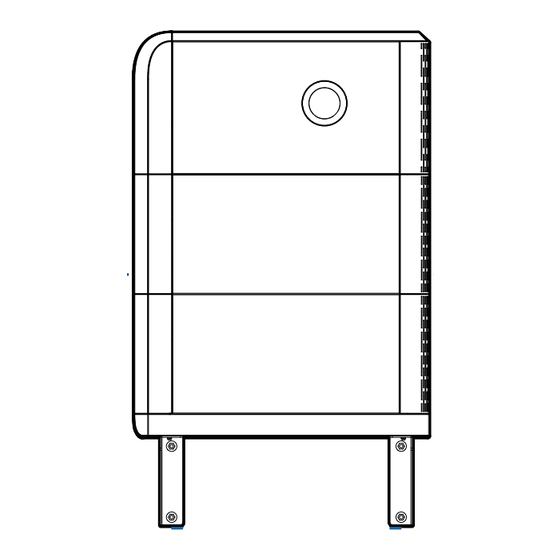
Page 12: Appearance Introduction
User Manual Appearance Introduction 2.2.1 Appearance and Dimensions Inverter and Battery Pack CommMod 12 / 40... -
Page 13: Port Introduction
User Manual 2.2.2 Port Introduction SigenStor EC/ SigenStor AC/Sigen Hybrid Left View Name Marking Decorative cover strip light connector LED Network interface RJ45 1/ RJ45 2 DC input interface PV1+/PV2+/ PV3+/PV4+/ PV1-/PV2- /PV3-/PV4- AC output interface Communication interface Ground screw Switch button ON/OFF DC switch... -
Page 14: Label Description
User Manual Label Description Symbols Definition Danger! High Voltage High voltage exists inside the equipment when powered on. Do not open the casing when the equipment is running. Any maintenance or servicing operations must be performed by trained and skilled electrical engineers. Warning! Life at risk. -
Page 15: Supported Power Supply Methods For The Power Grid
User Manual Supported Power Supply Methods for the Power Grid The grid supply methods supported include TN-S, TN-C, TN-C-S, TT and IT. When TT is used as the power supply technique for the power grid, the voltage between N and PE is required to be < 30 V. 15 / 40... -
Page 16: Introduction To System Wiring
User Manual Introduction to system wiring Our company’s products can be used for Home energy storage system. The Home energy storage system consists of photovoltaic panels, inverters, battery packs, master control switches, Gateway, loads, power grids, etc. The main function of Home energy storage system is to store the direct ... - Page 17 User Manual Whole home backup system wiring diagram A. PV panel B. SigenStor EC/SigenStor AC /Sigen Hybrid C. SigenStor BAT D. Gateway E. Backup Distribution panel F. Backup Household loads G. Diesel generator H. Smart loads I. Power grid J. mySigen K.
- Page 18 User Manual diesel generator can work in tandem with the Gateway to provide a smooth transition between PV, storage and diesel generation. All the power equipment in the owner's home can be connected as smart loads. To ensure that this product maximizes the benefits to users, it is recommended that the high-power equipment be connected as smart loads (heat pumps, pool heaters, clothes dryers, etc.), which can be cut off when the energy storage system has low power.
- Page 19 User Manual Partial home backup system wiring diagram A. PV panel B. SigenStor EC/SigenStor AC /Sigen Hybrid C. SigenStor BAT D. Gateway E1. Backup Distribution panel E2. Non-Backup Distribution panel F1. Backup Household loads F2. Non-Backup Household loads G. Diesel Generator H.
- Page 20 User Manual If F1 (backup household load) experiences leakage, it may pose a risk of electric shock. In order to avoid this hazard, a residual current device (RCD) must be installed between the D (Gateway) and the F1 (backup household load).
- Page 21 User Manual Non-backup system wiring diagram A. PV panel B. SigenStor EC/ SigenStor AC/Sigen Hybrid C. SigenStor BAT D.AC switch E. Distribution panel F.Household loads G. Power sensor H. Power grid I. mySigen J. Router K. Antenna L. CommMod No more than 25 SigenStor units can be cascaded. ...
- Page 22 User Manual SigenStor EC/SigenStor AC/Sigen Hybrid (5.0-8.0) TP: The rated current is 25 A SigenStor EC/SigenStor AC/Sigen Hybrid (10.0-15.0) TP: The rated current is 32 A SigenStor EC/SigenStor AC/Sigen Hybrid (17.0-20.0) TP: The rated current is 40 A SigenStor EC/SigenStor AC/Sigen Hybrid 25.0 TP: The rated current ...
-
Page 23: Chapter 3 Site Selection Requirements
User Manual Chapter 3 Site Selection Requirements The warranty applies when the equipment has been installed properly for its intended use and in accordance with the operating instructions. During actual installation, the selection of the installation location should comply with local regulations, firefighting regulations, and other relevant laws. - Page 24 User Manual Do not install the equipment in areas easily accessible to children. Do not install the equipment in a place with fire hazards or is prone to moisturizing. The equipment produces sound when it is operating. Please install the ...
- Page 25 User Manual The maximum operating temperature range applicable to the equipment is -20°C to 55°C, and the recommended optimal operating temperature range is 10°C ≤ T ≤ 35°C. When the battery pack temperature is below 0°C, immediate charging is ...
-
Page 26: Chapter 4 Equipment Installation And Wiring
Chapter 4 Equipment Installation and Wiring Only company authorized personnel should install and connect the equipment. For details, see SigenStor Home Installation Guide - Three- phase System A1. Parts and accessories supplied with the packing box are personal assets of the owner and must be kept safe. -
Page 27: Chapter 5 System Operation
User Manual Chapter 5 System Operation Working Mode There are six operating modes of the energy storage system: Sigen AI Mode, Fully Fed to Grid Mode, Self-Consumption Mode, Time-based Control Mode, Remote EMS Mode, Load Shedding. Sigen AI Mode can be used in some countries, which is explicitly stated ... - Page 28 User Manual maximum output capacity of the inverter or when no PV power is generated at night, the batteries are discharged to ensure that the inverter can maximize the output. Self-Consumption Mode When there is sufficient solar power, the electric energy generated by the PV system will first be used to power the loads, with any excess energy being stored in the batteries.
- Page 29 User Manual Remote EMS Mode After setting to this mode will allows a third-party EMS to schedule parameters related to the power station and the product set by the company. Do not enter or exit this mode without the installer's confirmation. Load Shedding In areas with frequent power outages, you can add your region and schedule in this mode, and the system will fully charge the battery in advance as scheduled,...
- Page 30 User Manual 30 / 40...
-
Page 31: Led Indicator State
User Manual LED Indicator State SigenStor EC/ SigenStor AC/Sigen Hybrid Indicator Indicator Color State Description Always on The DC side is connected but not running. Always on The DC side is running. The DC side is not connected. Flash The DC side is faulty. Always on Inverter failure. - Page 32 User Manual Indicator Color State Description The management system is not connected. Flash Connected to local App. Always on Connected to the management system using an FE or WLAN. Always on Connected to the management system over 4G. Flash Insufficient traffic for Sigen CommMod. CommMod Indicator Name State...
-
Page 33: Mysigen App Query
User Manual mySigen App Query The App can be downloaded in the following two ways. For details, see mySigen App User Manual. 33 / 40... -
Page 34: Chapter 6 System Maintenance
User Manual Chapter 6 System Maintenance Routine Maintenance To ensure the long-term operating of the equipment, you are advised to perform routine maintenance according to this section. Inspection Inspection method Power off Maintenance content or not cycle System Regularly check whether the Once every cleaning decorative cover or fan is covered... -
Page 35: Equipment Power-On/Power-Off
User Manual Equipment Power-on/Power-off Scheme 1: App operation In the mySigen app, tap "Settings" to turn the device on or off. 35 / 40... - Page 36 User Manual Scheme 2: Manual operation Follow the steps shown to remove the side and top decorative cover, and press the ON/OFF switch button. Press and hold for more than 3s to turn on or off the power; an interval of more than 10s is needed between power-on and power-off.
-
Page 37: Low Soc
User Manual Low SOC The self-discharge characteristic of battery pack will cause power loss. If the equipment is not charged for a long time, it may be damaged due to overdischarge of power. When the battery is low, charge the equipment in time. Under normal circumstances, the equipment can charge itself according to the running condition. -
Page 38: Emergency Treatment
User Manual Emergency Treatment Emergency in case of Fire Please shut down the equipment or disconnect the main power switch when it is safe. The high temperature may distort or damage the battery pack, resulting in electrolyte overflow or toxic gas leakage. Do not go near the battery pack and wear protective equipment. - Page 39 User Manual Emergency in case of Battery Pack Malfunctions When the battery pack has abnormal odor, electrolyte leakage, or heat, do not touch it, and contact professional personnel immediately. Professionals must wear protective equipment such as goggles, rubber gloves, gas masks, and protective clothing to protect themselves. The electrolyte is corrosive and contact may cause skin irritation or ...
-
Page 40: Chapter 7 Appendix
User Manual Chapter 7 Appendix Technical Parameter For details about equipment parameters, see the Data sheets of the product. 40 / 40...
Need help?
Do you have a question about the SigenStor Home and is the answer not in the manual?
Questions and answers
How do you change the system default settings for the maximum power imported from the grid
I have a 3Phase 144kw (18 batteries) system with 12kw inverters. Why does my battery system not start to charge until the load being drawn from the grid drops below 35kw.