
Subscribe to Our Youtube Channel
Related Manuals for Beck 42-109


Summary of Contents for Beck 42-109
- Page 1 MODEL 42-109 80-0042-01 Rev. 02 INSTRUCTION MANUAL CERTIFIED E L E C T R I C A C T U A T O R S F O R I N D U S T R I A L P R O C E S S C O N T R O L...
-
Page 2: Introduction To The Manual
Beck Model long, linear stroke applications requiring up to 42-109 Electronic Control Drives, manufactured by Harold Beck & Sons, Inc. of Newtown, 1,000 lbs. of thrust. Pennsylvania. NOTICE: This manual includes information that will make installation simple, efficient, and trouble- free. -
Page 3: Table Of Contents
80-0042-01 CONTENTS Product Description ........................... 4 General Specifications ..........................6 Outline Dimension Drawings ........................8 Installation ..............................10 Signal Wiring ............................11 Operation ..............................12 Digital Control Module (DCM) ........................14 DCM Local Interface Operation ............................15 Calibration ............................17 Switches ............................18 Demand ............................ -
Page 4: Product Description
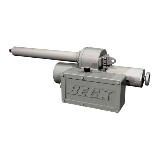
Protection Concepts, suitable for use in: slot in the Beck family of products. As with all Beck drives, the Group 42 is Class II, Division 1, Groups E, F and G; T4A designed for simple installation, no duty cycle... - Page 5 80-0042-01 42-109 Cutaway View Rear Mounting Clevis Actuator Housing Handswitch Handwheel Motor Output Shaft Clevis Contactless Position Sensor (CPS) Switches Digital Control Module Wiring Terminal Board (DCM)
-
Page 6: 42-109 General Specifications
80-0042-01 PRODUCT DESCRIPTION 42-109 GENERAL SPECIFICATIONS Output Thrust and Timing 1,000 lbs., 4.2 sec/in Stroke Range 8 to 18 inches Drive Power 120 V ac, single-phase, 50 or 60 Hz, 1.5 A 240 V ac, single-phase, 50 or 60 Hz, .75 A Weight Approx. - Page 7 80-0042-01 Over-travel Limit Two Form C (Retract and Extend) provide over-travel protection. Switches Auxiliary Switches Two Form C rated for 1 A, 250 V ac. (Field adjustable) Handswitch Permits local electrical operation, independent of Demand input signal. Handwheel Provides manual operation without electrical power. Motor 120 V ac, single-phase, no burnout, non-coasting.
-
Page 8: Outline Dimension Drawings
80-0042-01 OUTLINE DIMENSION DRAWINGS MODEL 42-109 SPECIFICATIONS (All dimensions are in inches & [mm] and are subject to change) “L” DIMENSION ±3/8” [10] 1 1/16” 3/4” ±1/16 [27] .754 ±.003 DIA. THRU [19 ±2] [19 ±.076] 11/16” ±1/16” [17 ±2] ø... -
Page 9: Rear View
80-0042-01 6 17/32” [166] 3 7/16” 3 1/2” [89] [87] .625 ±.010 .625 ±.010 [15.875 ±.254] [15.875 ±.254] 1 9/16” 2 5/8” [40] [67] XXXXXXXXXXXXXXXXXXXXX XXXXXXXXXXXXXXXXXXXXX XXXXXXXXXXXXXXXXXXXXX XXXXXXXXXXXXXXXXXXXXX XXXXXXXXXXXXXXXXXXXXX XXXXXXXXXXXXXXXXXXXXX XXXXXXXXXXXXXXXXXXXXX 3 13/32” XXXXXXXXXXXXXXXXXXXXX XXXXXXXXXXXXXXXXXXXXX XXXXXXXXXXXXXXXXXXXXX XXXXXXXXXXXXXXXXXXXXX XXXXXXXXXXXXXXXXXXXXX XXXXXXXXXXXXXXXXXXXXX XXXXXXXXXXXXXXXXXXXXX XXXXXXXXXXXXXXXXXXXXX XXXXXXXXXX XXXXXXXXX... -
Page 10: Installation
After unpacking, Refer to the wiring diagram furnished with this platform may be used to transport the drive to your Beck drive for proper AC power and signal the installation site. connections. It is advisable to provide normal short circuit protection on the AC power line. -
Page 11: Signal Wiring
80-0042-01 INSTALLATION SIGNAL WIRING Each Beck drive is custom built to match the control requirements of your system specified at the time of order. Each drive has a specific wiring diagram attached to the inside of the wiring terminal cover. Typical wiring connections are described below. -
Page 12: Operation
Handwheel, reduction gears, main gear and output proper operation. shaft. The output shaft is limited by mechanical stops to 1/8" beyond the maximum stroke range. NOTE: All Beck drives are shipped from the factory ready for installation; no electrical SELF-LOCKING adjustments are required before placing MECHANISM (SLM) them in operation. - Page 13 80-0042-01 LOSS OF DEMAND INPUT STALL PROTECTION AND SIGNAL (L.O.S.) ANNUNCIATION When the Demand input signal drops to If the drive output shaft cannot reach a desired approximately –5%, the DCM considers the position within approximately 300 seconds, the Demand input signal to be invalid. DCMs are DCM shuts off power to the motor and the “ERR”...
-
Page 14: Digital Control Module (Dcm)
4–20 mA or 1–5 V dc control reporting and to assist in troubleshooting. signals directly—eliminating the need for contact The DCM permits two or more Beck drives to protection devices, relays, switches and reversing be operated by a single signal source. See "split starters. -
Page 15: Dcm Local Interface
“Status Indication LEDs”. This LED is lit when power is applied to the drive. NOTE: Beck drives are shipped from the factory set up and calibrated to customer specifications placed at the time of order and are ready for installation. - Page 16 80-0042-01 DCM LOCAL INTERFACE Operation Status Indication LEDs Pushbutton Controls When the “STAT” LED is lit, the applicable The five pushbuttons (pictured below) on status indication LED(s) (pictured below) will light the DCM customer interface panel are used for to reveal the condition(s) as described below. An calibration.
-
Page 17: Calibration
80-0042-01 DCM LOCAL INTERFACE Calibration CALIBRATION PRIORITY All Beck drives are shipped completely calibrated to the customer’s specifications that Group 42 drives are equipped with fixed, non- were written into the equipment order and are adjustable, built-in mechanical stops. All output ready to be installed. -
Page 18: Switch Calibration
SWITCH CALIBRATION Switches are operated by cams which are clamped onto the control shaft. Setting a switch NOTE: Your Beck drive was shipped from the involves moving the drive’s output shaft to the factory ready for installation; no electrical desired position and positioning the cam so adjustments are required before placing it in that it operates the switch at that point. - Page 19 80-0042-01 8. Use the Handwheel and confirm that the 1. Remove the control end cover and the terminal contacts are open in the normal operating range block cover (1/2" bolt heads). and close at the desired over-travel limit. 2. Move the output shaft to the desired position. 9.
-
Page 20: Demand
80-0042-01 DCM LOCAL INTERFACE Calibration - Demand DEMAND CALIBRATION Calibration Procedure DCM boards are designed to accept a 4–20 mA 1. Remove the DCM cover (1/2” bolt heads). (or 1–5 V dc) analog Demand signal. Narrower 2. Ensure the Handswitch is in the “STOP” spans within this range can also be accommodated position. - Page 21 Square Function NOTE: Ensure that the L.O.S. (Loss of Beck drives can be set up to position the output Demand input signal) settings of the drives are shaft proportionally to the square of the Demand appropriate for the configuration. See page 13 input signal (see table below).
-
Page 22: Position Calibration
80-0042-01 DCM LOCAL INTERFACE Calibration - Position POSITION CALIBRATION 10. Replace the compartment cover and tighten the cover bolts to 10 lb-ft torque. In order to correctly position the drive output shaft in response to the Demand input signal, the DCM * If the “ACKNOWLEDGE”... -
Page 23: Direction Change
80-0042-01 DCM LOCAL INTERFACE Calibration - Direction Change DIRECTION OF OUTPUT Changing the direction of output shaft travel is easily accomplished using the DCM customer SHAFT TRAVEL (EXTEND VS. interface panel (see page 16 for location of RETRACT) pushbutton controls) or the HART or Serial interface. -
Page 24: Dcm Hart Interface
1.000 v 2 Descriptor* 4 CPS Span 4.000 v 3 Message* 5 CPS RngLwr 1.000 v Dem Curve Spcl 4 Model# 42-109 6 CPS RngUpr 5.000 v 1 DemNode1X 5 Drive S/N* 7 Pos S/N* 2 DemNode1Y 6 Instld* 23/05/2006... - Page 25 80-0042-01 275/375 HANDHELD COMMUNICATOR WIRING CONNECTIONS CONTROL FIELD ROOM CONTROLLER DEMAND FIELD JUNCTION BOX OUTPUT TO DRIVE TERMINATION MARSHALLING CABINET ACCEPTABLE COMMUNICATOR CONNECTION POINTS POLARITY IMPORTANT DEMAND SIGNAL A 250 load resistor TO DRIVE WIRING may be required for (TERMINAL AA & BB) proper HART communication when the DCM has been modified for...
- Page 26 HART INTERFACE ® between the user and the Beck drive. The bottom Figure 1, page 24, displays the interface line of the LCD displays dynamic labels that define menu tree for communicating with a DCM via...
-
Page 27: Menu Descriptions
80-0042-01 MENU DESCRIPTIONS follow the questions and prompts to successfully complete the setup. The primary purpose of the (See Figure 1, Page 24) Setup Checklist is to aid in the retrofit installation of a DCM board into an existing drive. It is Online Menu normally not necessary to go through the Setup (Block 1) - Page 28 80-0042-01 DCM HART INTERFACE Communication ’ 2. MaxTravel - The maximum available travel evice nformation menu cont distance of the output shaft in inches. the “Device Information” menu, the user This value is entered manually, and must is prompted at the end of performing any correspond to the actuator design.
- Page 29 80-0042-01 4. CPS Span - Displays the CPS voltage span 8. DemLimUpr - Sets the maximum usable for the maximum allowable output shaft value of Demand. This value should be travel. set higher than the upper Demand Range 5. CPS RngLwr - Displays the CPS voltage at ("DemRngUpr").
- Page 30 80-0042-01 DCM HART INTERFACE Communication Statistics Menu Manual Operation Menu (Block 3D) (Block 3E) This menu is where all the drive’s stored This menu is used to allow manual drive operating statistics are available. There are eight operation with the HART communicator.
- Page 31 80-0042-01 Op Mode Submenu RET Inhibitors Submenu (Block 4G) (Block 5F) This menu is used to allow selection of the This menu displays the ON or OFF status operating mode of the DCM with the HART of the contributing sources of retract movement ®...
- Page 32 80-0042-01 DCM HART INTERFACE Communication Tests Submenu Extend Thrust Submenu (Block 4I) (Block 4J) This menu provides procedures that allow the This menu displays the thrust applied over ten user to test, identify and reset the DCM board. segments of travel as the drive shaft extends. They are as follows: 1.
- Page 33 80-0042-01 Calibration Trim Menu (Block 3G) This menu displays/sets drive calibration values: 1. PresCPS V - Displays the present value of the internal Position Sensor voltage. This value can also be measured at TP4(+) and TP1(–) on the DCM board. This value can be edited to trim the Position Sensor.
-
Page 34: Configuration
Menu Tree and defines all the WARNING ® parameters and commands. If unfamiliar with Carefully follow the on-screen the HART communicator and Beck drives, ® warnings and messages when please review the Communications section proceeding, because changing before proceeding. this parameter will cause the drive There are a number of configuration setup to reposition. -
Page 35: Stall Protection
80-0042-01 STEP 3 - With the desired value correctly NOTE: It is possible that the stall time can typed into the entry box, push the F4 function key be set to a value less than the full travel time which is defined as the ENTER key at the bottom of some drives. -
Page 36: Position Feedback Signal
0% and an over-travel limit switch is open. This eliminates the nuisance message, but does not The Beck DCM is designed to receive a eliminate the message for other scenarios like 4–20 mA (1–5 V dc) input Demand signal and the Handswitch being in the STOP position. - Page 37 80-0042-01 WARNING ENTER key at the bottom of the display. Pushing this key enters the selected parameter and reverts Carefully follow the on-screen the display back to the “Demand setup” main warnings and messages when menu. If the “Go-to-Pos” choice was selected, go proceeding, because changing to STEP 4, if “Stay”...
- Page 38 80-0042-01 DCM HART INTERFACE Configuration and Setup Enabling Thrust Functions loS t ’ hanging oint cont STEP 4 - At the bottom of the “Demand Setup” STEP 1 - From the HART communicator ® menu, the F2 function key should now be defined “Online”...
- Page 39 80-0042-01 Enabling Over-thrust Protection STEP 1 - From the HART communicator ® “Online” menu, move to the “Thrust Setup” menu, make sure that the “Trq/Thrust” parameter is enabled (if not, enable it using the prior procedure) and select the “Ovt Prot” parameter. This is accomplished by using the up and down arrow keys to select the appropriate item in each menu and then moving forward by pressing the...
-
Page 40: Calibration
80-0042-01 DCM HART INTERFACE Calibration All Beck drives are shipped completely calibrated to the customer specifications, and are ready to be installed. If the need arises to change the drive calibration, confirm that the drive is installed as specified and operating properly before proceeding with the change. - Page 41 80-0042-01 DIRECTION OF SHAFT CALIBRATION PRIORITY TRAVEL (RETRACT VERSUS Group 42 drives are equipped with fixed, non- adjustable, built-in mechanical stops. All output EXTEND) shaft movement must occur within these stops, Direction of shaft travel is determined when which are approximately 1/8" beyond each end of looking at the output shaft.
-
Page 42: Switches
SWITCH CALIBRATION Switches are operated by cams which are clamped onto the control shaft. Setting a switch NOTE: Your Beck drive was shipped from the involves moving the drive’s output shaft to the factory ready for installation; no electrical desired position and positioning the cam so adjustments are required before placing it in that it operates the switch at that point. -
Page 43: Pin Connectors
80-0042-01 8. Use the Handwheel and confirm that the 1. Remove the control end cover and the terminal contacts are open in the normal operating range block cover (1/2" bolt heads). and close at the desired over-travel limit. 2. Move the output shaft to the desired position. 9. -
Page 44: Position Reference
"PositionSensrSetup" submenu is used to set the DCM to accept the CPS position signal and interpret the appropriate 0–100% range. All Beck drives are shipped completely set and calibrated to the customer specifications and are ready for installation. Normally, no adjustments are necessary. - Page 45 80-0042-01 Short-stroke Operation (Reducing Full Travel) Typically, it is best to use the full 100% travel of the drive in response to the 0–100% Demand input signal. In certain applications, as a last resort, it may become necessary to reduce the full travel of the drive.
-
Page 46: Position Feedback
80-0042-01 DCM HART INTERFACE Calibration - Feedback FEEDBACK SIGNAL CALIBRATION DCM boards have the capability of providing a 4–20 mA output signal so that the drive’s true output shaft travel can be monitored remotely. The signal comes calibrated from the factory to provide a precise 4–20 mA signal corresponding to 0–100% drive travel. -
Page 47: Demand Input
Often, this type of control 4–20 mA (or 1–5 V dc) analog Demand signal. strategy requires that two to four Beck drives Narrower spans within this range can also be each respond to different portions of one 4–20 accommodated for split range operation (see mA Demand signal from the control system. -
Page 48: Torque Measurement
80-0042-01 DCM HART INTERFACE Calibration - Thrust Measurement THRUST MEASUREMENT CALIBRATION DCM boards have the capability of measuring the drive output thrust and providing several thrust-related features. The thrust measurement is calibrated to the drive’s rated output at the factory. There is normally no reason to recalibrate this feature in the field, unless a new DCM board has been installed. -
Page 49: Maintenance
(optional) or temperature measurement is outside the design or calibrated ranges. The Beck specific messages below provide more descriptive information. This is a Beck-specific message that can appear after the HART “Demand signal out of range” ® defined message above. It specifically pinpoints the Demand input signal to the DCM as the problem source, and indicates that the signal is outside the calibrated range limits. - Page 50 DCM HART INTERFACE Maintenance - Alarm Messages Message Description This is a Beck-specific message that can appear after the HART “Thrust is excessive” ® defined (“Process applied to the non-primary variable is outside the operating limits of the field device”) message mentioned previously.
- Page 51 Miscellaneous Messages Message Description This is a Beck-specific alarm message that alerts the user that “Feedback circuit is disconnected” external position feedback signal is installed and enabled, but not wired to an external load. If the signal is wired to an external...
-
Page 52: Dcm Serial Inferface
COMMUNICATIONS Once the computer has been connected to the DCM, access HyperTerminal by clicking first The Beck Digital Control Module (DCM) is on "Start", then "Programs", then "Accessories", equipped with a serial interface which allows for then "Communications", then "HyperTerminal". -
Page 53: Commands
80-0042-01 DCM SERIAL INTERFACE Commands COMMANDS AND ARGUMENTS Commands can be used for a variety of functions including changing the operating configuration of the drive, verifying operation settings, calibration and accessing diagnostic information. There are essentially four different types of commands: 1. -
Page 54: Serial Commands
80-0042-01 DCM SERIAL INTERFACE Commands SERIAL COMMANDS The following is a list of serial commands available through the RS-232 interface. Error codes associated with these commands are listed on page 59. General Configuration Commands (p. 55) stepsize drvdir stalltime sernum Reset Factory Settings Commands (p. - Page 55 80-0042-01 Note: For specific information on the following functions, see the HART interface section of the manual. General Configuration Commands Command Description Argument n and Information stepsize n Sets and/or displays the size (in n = stepsize in degrees. The minimum degrees) of one incremental movement value that can be entered is "0.10";...
- Page 56 80-0042-01 DCM SERIAL INTERFACE Commands Note: For specific information on the following functions, see the HART interface section of the manual. Demand Signal Commands (con't) Command Description Argument n and Information trimdem4ma 4 Calibrates the Demand signal at 4 mA. This A 4 mA Demand signal must be command should only be used when the present at drive terminals 14 &...
- Page 57 80-0042-01 Position and Feedback Signal Commands Command Description Argument n and Information travel n Sets and/or displays the value that n = the desired length of travel in inches represents 100% travel. or millimeters. fdbk0pctma n Sets and/or displays the mA value of the n = the desired Feedback signal for Feedback signal that represents the 0% 0% drive position in mA.
- Page 58 80-0042-01 DCM SERIAL INTERFACE Commands Note: For specific information on the following functions, see the HART interface section of the manual. Thrust Sensing Commands (con't) Command Description Argument n and Information thrustconst n Assigns the count value to be n = the thrust span value in counts. associated with the thrust span.
-
Page 59: Error Codes
80-0042-01 DCM SERIAL INTERFACE Command Error Codes Command Error Codes When an error is encountered using the serial commands, an "ERROR XX" message is returned. The table below provides a description of the error codes ("XX"). Code Description Information Invalid selection Displayed when an unknown command has been entered. - Page 60 80-0042-01 NOTES...
- Page 61 80-0042-01...
-
Page 62: Maintenance
80-0042-01 MAINTENANCE ROUTINE HOW TO ORDER SPARE PARTS Beck drives require only a minimum of routine Any customer replacement kit may be maintenance. A visual inspection is in order purchased for spare parts. Contact your Beck to verify that the connection to the final control Sales Engineer for recommended replacement element is intact and operating normally. -
Page 63: Services
1) the repair or replacement, without charge, at Beck’s factory, of any defective equipment covered by this warranty, or 2) at Beck’s option, a full refund of the purchase price. In no event will Beck’s liability exceed the contract price for the goods claimed to be defective. - Page 64 HAROLD BECK & SONS, INC. 11 TERRY DRIVE NEWTOWN, PENNSYLVANIA 18940 USA PHONE: 215-968-4600 FAX: 215-860-6383 www.haroldbeck.com 05/12...
Need help?
Do you have a question about the 42-109 and is the answer not in the manual?
Questions and answers