
Related Manuals for Beck 11-483


Summary of Contents for Beck 11-483
- Page 1 MODEL 11-483 80-1100-24 Rev. 1.1 INSTRUCTION MANUAL E L E C T R I C A C T U A T O R S F O R I N D U S T R I A L P R O C E S S C O N T R O L...
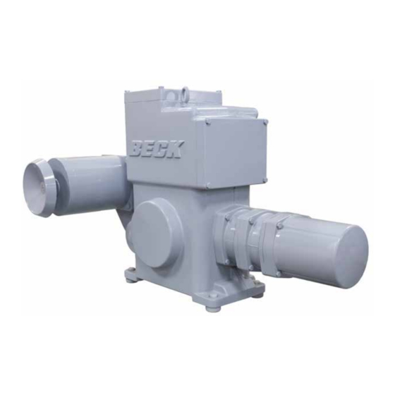
- Page 2 Harold Beck & time-proven reliability, features, and performance Sons, Inc. of Newtown, Pennsylvania. advantages. For applications requiring up to 120 lb-ft (163 N•m) of actuator torque, the 11-483 is available with multiple travel span options, ranging from 5 turns to 408 turns.
-
Page 3: Table Of Contents
80-1100-24, Rev. 1.1 TABLE OF CONTENTS Introduction ........................2 General Specifications ....................4 Outline Dimension Drawings ..................6 Precautionary Information ....................7 Component Location .......................8 Installation ........................9 Mechanical ........................9 Electrical ........................10 Wiring ......................... 11 Start-up ...........................12 Operation ........................13 Calibration ........................14 Switches........................14 Optional Relay Board ....................16 Maintenance ........................17 Routine ........................17 Component Replacement ..................18... -
Page 4: General Specifications
-15% Maximum Current (Amps) by Supply Voltage Voltage (Vac) Maximum Model Power (VA) 11-483 Operating Conditions -40° to 85°C (-40° to 185°F) 0 to 100% relative humidity, non-condensing. Direct AC Control 120 Vac for 2-position control. Action of Loss of Power Stays in place. - Page 5 80-1100-24, Rev. 1.1 Output Shaft Rotation Dependent on the control end (see below). Control End Assembly (part no.) Travel Range (turns) 23-2348-10 5–9 23-2348-11 7–14 23-2348-12 14–25 23-2348-13 25–45 23-2348-14 35–70 23-2348-15 65–126 23-2348-16 115–227 23-2348-17 200–408 Mounting Orientation Any orientaton—no limitations. Standards CSA Labeled (US &...
-
Page 6: Outline Dimension Drawings
80-1100-24, Rev. 1.1 OUTLINE DIMENSION DRAWINGS MODEL 11-483 SPECIFICATIONS MOUNTING HOLES 5/8-11 UNC-2B x 1.63” [4.14 cm] DEEP (4 PLACES) (9 3/4” [24.8 cm] B.C.) TYPICAL VALVE MOUNTING Ø13/16” [2.0 cm] MOUNTING HOLES 7” 6 3/4” OPTIONAL (4 PLACES) [17.8 cm] [17.1 cm]... -
Page 7: Precautionary Information
STORAGE INFORMATION Beck actuators should be stored in a clean, INSTALLATION—ELECTRICAL dry area where the temperature is between -40° and 85°C (-40° to 185°F). See the instructions beginning on page 10 for Damage due to moisture while in storage is details regarding electrical installation. -
Page 8: Component Location
STOP position before manually output shaft using the Handswitch, the motor will operating the Handwheel. stop when the limit switches are reached. Cover, Wiring Terminal Block Motor Conduits Cover, Control End Handswitch Over-travel Limit and Auxiliary Switches Control Gear Module Gearing 11-483 COMPONENTS... -
Page 9: Installation
80-1100-24, Rev. 1.1 INSTALLATION Mechanical INSTALLATION—MECHANICAL The 11-483 actuator may be installed in any convenient orientation, because the gearing does not require an oil bath. Refer to the outline dimension drawings for physical dimensions and required clearances. VALVE INSTALLATIONS CAUTION Working with valves and gates can be dangerous. -
Page 10: Electrical
Refer to the wiring diagram furnished with your Beck actuator for proper AC power and signal Shielded, twisted pair cables can be used for connections. The customer must supply 120 Vac to signal connections to avoid being affected by power the actuator (standard configuration). -
Page 11: Wiring
Line voltage connections are made on terminal designations A through V. Low voltage signaling terminals designated AA through EE are not used in the 11-483. Actuators equipped with optional transformers to accommodate popular voltages include an additional terminal strip and fuse for power wiring (with the exception of the 240 volt option). -
Page 12: Start-Up
80-1100-24, Rev. 1.1 START-UP INSTALLATION Wiring POWER CONNECTIONS FOR NOTE: All Beck actuators are shipped from the ALTERNATE POWER OPTIONS factory ready for installation. Each actuator is set-up and calibrated to the customer’s specifications that were written into the Optional Transformer for equipment order. -
Page 13: Operation
OPERATION HOUSING HANDSWITCH Beck electric actuators have individual cast A local electric Handswitch is provided on Beck aluminum compartments for each of the five main actuators to permit operation at the valve or damper, components: The control motor, wiring terminal indepen dent of the controller. As a safety feature,... -
Page 14: Calibration
80-1100-24, Rev. 1.1 CALIBRATION Switches SETTING LIMIT SWITCHES NOTE: Your Beck actuator was shipped from the factory ready for installation; no CW AND CCW electrical adjustments are required before This procedure should be used if the factory placing it in operation. Each actuator is set limit switch settings must be changed in the field. -
Page 15: Switches
80-1100-24, Rev. 1.1 SETTING AUXILIARY SWITCHES Standard switch settings are shown on the following diagram “Standard Limit and Auxiliary Switch Settings”. The heavy line indicates a closed circuit. Follow these instructions to change the operating point of auxiliary switches: NOTE: In the following procedure, it is assumed that switch settings are to be adjusted so that contacts are open when the desired position is achieved. -
Page 16: Maintenance
LUBRICATION / GEARING Examine the gear teeth, shaft bore, and gear shafts for signs of excessive wear, scoring, or Periodic lubrication is not required on Beck other damage. If there is no evidence of damage actuators. to the gearing, recoat the teeth and shaft bores... -
Page 17: Component Replacement
Bearings The Beck electric actuator contains ball bearings on the output shaft, control end shaft, and motor shaft. Bushings and thrust washers are used on combination gears. Field replacement of these components is not recommended. - Page 18 80-1100-24, Rev. 1.1 MAINTENANCE Component Replacement SELF LOCKING MECHANISM It is often possible to confirm SLM wear or damage by checking motor operation with the (SLM) Handwheel. Place the Handswitch in the STOP The Self Locking Mechanism (SLM) is position, and rotate the motor Handwheel back assembled to the front of the motor and couples and forth.
- Page 19 Remove the (4) 1/4-20 screws and the front motor end. DO NOT remove the front motor shield or the rotor from 11-483 SLM COMPONENTS the stator on any model. CAUTION Do not disassemble the motor any further, as it has no other user serviceable parts.
- Page 20 80-1100-24, Rev. 1.1 MAINTENANCE Component Replacement REPLACEMENT AND REBUILD INSTRUCTIONS 1. If the friction material requires replacement, scrape off the old friction material and thoroughly clean the bonding surface to ensure flatness for the new friction material. Glue the new friction material in place with Loctite 454 Instant Adhesive or equivalent, taking care to keep the material flat and clean.
- Page 21 80-1100-24, Rev. 1.1 OVER-TRAVEL LIMIT AND AUXILIARY SWITCHES Complete switch assemblies may be replaced. It is not possible to replace individual switches. To replace switch assemblies, follow the instructions below. WARNING WARNING Electrical shock hazard. Disconnect power before proceeding. Remove the control end cover by loosening the .030”...
- Page 22 80-1100-24, Rev. 1.1 MAINTENANCE Component Replacement FUSE (F1) REPLACEMENT (FOR ACTUATORS EQUIPPED WITH OPTIONAL 208V OR HIGHER POWER SUPPLY) If it is necessary to replace the power fuse (F1), use the following procedure: WARNING WARNING Electrical shock hazard. Disconnect power before proceeding. Remove the terminal block cover.
- Page 23 80-1100-24, Rev. 1.1 HANDSWITCH 9. Splice the wires from the new Handswitch assembly to the wires from the actuator, color to color. Ensure the wiring is not exposed after WARNING WARNING splicing. Electrical shock hazard. Disconnect power before proceeding. 10. Replace the terminal cover, tightening the captive screws to 10 Ib-ft (14 N•m).
-
Page 24: Spare Parts & Part Numbers
The Beck website (www.haroldbeck.com) provides an actuator serial number lookup tool The table below lists common recommended which will provide details specific to your actuator. spare parts for the 11-483 actuator. COMMON RECOMMENDED SPARE PARTS Description Part Number Fuse (F1) w/ operating voltage >120 V See page 22 Limit switch assy. -
Page 25: Troubleshooting
80-1100-24, Rev. 1.1 TROUBLESHOOTING If your unit contains a Stall Protection Module (SPM), refer to publication 80-0017-03, “Troubleshooting”. CONDITIONS POSSIBLE CAUSES CORRECTIONS Actuator motor oscillates in AUTO Physical obstruction (e.g., valve Check operation with Handswitch mode. jammed or load greatly exceeds and remove obstruction if present. actuator rating. -
Page 26: Optional Led Display
80-1100-24, Rev. 1.1 APPENDIX Optional LED Display The optional LED display board (p/n 22- The red and green LEDs, which are intended 5008-49) provides lighted color indication of the to indicate OPEN and CLOSE ends-of-travel actuator output position. The board resides in are easily set up by connecting jumpers on the the same location (the electronics compartment) actuator’s terminal block (see the wiring diagram... -
Page 27: Optional Locking Handswitch
80-1100-24, Rev. 1.1 APPENDIX Optional Locking Handswitch A locking Handswitch is available. When installed, the Handswitch may be locked into any position (as shown below). PAWL When the Handswitch knob is in the desired position, rotate the pawl to lock into place. 20-3320-75 (5-POSITION LOCK) - Page 28 80-1100-24, Rev. 1.1 NOTES...
- Page 29 80-1100-24, Rev. 1.1...
-
Page 30: Index
80-1100-24, Rev. 1.1 INDEX Appendices ..........26–27 Outline Dimension Drawings ......6 Optional LED Display ........26 Power Quality ..........10 Optional Locking Handswitch ...... 27 Precautionary Information ......... 7 Application Reviews ........31 Product Demonstrations ........31 Auxiliary Limit Switches ......15, 21 Self-Locking Mechanism (SLM) ... -
Page 31: Services
1) the repair or replacement, without charge, at Beck’s factory, of any defective equipment covered by this warranty, or 2) at Beck’s option, a full refund of the purchase price. In no event will Beck’s liability exceed the contract price for the goods claimed to be defective. - Page 32 HAROLD BECK & SONS, INC. Made in USA 11 TERRY DRIVE NEWTOWN, PENNSYLVANIA 18940 USA PHONE: 215-968-4600 FAX: 215-860-6383 E-MAIL: sales@haroldbeck.com 10/23 www.haroldbeck.com...
Need help?
Do you have a question about the 11-483 and is the answer not in the manual?
Questions and answers